it doesn’t sound good …
The problem in that case was getting the complementary channels to run while the pins for the non-complementary ones were in use for other purposes. I’m still not sure if that’s possible or not.
But your case where all 6 channels are running and just need to have non-inverted polarity on the complementary ones should definitely be doable.
Are you using dev branch? It looks like SIMPLEFOC_PWM_LOWSIDE_ACTIVE_HIGH is implemented there.
damned!
I installed library as explained in the “noobs directives” ('cause I’m a noobs)
and I can confirm the ‘non reference’ in stm32_mcu.cpp
what I did wrong?
Yes ![]() you have to define this flag at a global level, in the platformio.ini or the Arduino board files - it’s not enough to set it in your own code.
you have to define this flag at a global level, in the platformio.ini or the Arduino board files - it’s not enough to set it in your own code.
Alternatively you can modify the library code to change the default there.
sorry for my late answer, I was in we
okay I’ll try to modify platformio.ini …
nevertheless , I didn’t got the point : why my local library copy isn’t uptodate
okay…
so I remove the “simplefoc” library (release from git) by clicking on “remove lirary”
I downloaded the DEV revision form git , stored it on my local drive, created a symlink into the project’s lib folder by using mklink/J …
I have now the file directly showed by VScode… AND I can see the famous switch SIMPLEFOC_PWM_LOWSIDE_ACTIVE_HIGH
good…
I press “compile” … and failed
- Looking for SimpleFOC.h dependency? Check our library registry!
- CLI > platformio lib search “header:SimpleFOC.h”
- Web > PlatformIO Registry
2 | #include <SimpleFOC.h>
  |          ^~~~~~~~~~~~~
compilation terminated.
damned…! puzzled, and feeling… old, very old ![]()
least I can say that … I’m not a pilot !
my mistake, the symlink wasn’t precise enough, lacking a directory level…
so now I’m sure I have a “dev” library compiling :
lib\Arduino-FOC\src\drivers\hardware_specific\stm32\stm32_mcu.cpp:10:49: note: ‘#pragma message: SimpleFOC: compiling for STM32’
10 | #pragma message(“SimpleFOC: compiling for STM32”)
| ^
I still have a warning :
Warning! Ignore unknown configuration option -dsimplefoc_pwm_lowside_active_high in section [env:genericSTM32F103C8]
then… my wrap up following :
-the compilation switch -dsimplefoc_pwm_lowside_active_high = false is ignored on my config
-the define #define SIMPLEFOC_PWM_LOWSIDE_ACTIVE_HIGH false is also ignored.
if I abruptly change the lib as follow :
uint32_t polarity = SIMPLEFOC_PWM_HIGHSIDE_ACTIVE_HIGH ? TIM_OCPOLARITY_HIGH : TIM_OCPOLARITY_LOW;
  //FSI just tot test uint32_t Npolarity = SIMPLEFOC_PWM_LOWSIDE_ACTIVE_HIGH ? TIM_OCNPOLARITY_HIGH : TIM_OCNPOLARITY_LOW;
  uint32_t Npolarity =  TIM_OCNPOLARITY_LOW;
it works!
where did I f. up?
_edit___
stop the press! finally I make my wheel rotating in open loop mode!
amazing!
#define SIMPLEFOC_PWM_LOWSIDE_ACTIVE_HIGH false
#include <SimpleFOC.h>


// uint32_t Npolarity =  TIM_OCNPOLARITY_LOW; line 341 must be set in sstm32_mcu.cpp
// uint32_t polarity = TIM_OCPOLARITY_LOW; line 246 must be set in sstm32_mcu.cpp
//platform STM32F103C8T6
//with MPU6050

HardwareSerial SerialDebug(USART3);

int polePairs = 22;
#define ENC_A  PA0 // HallSensor A pin
#define ENC_B  PA1
#define ENC_C  PA2

#define LED_1  PA15
#define LED_2  PB4
#define LED_3  PB5
#define LED_4  PB8
int leds[] = { LED_1, LED_2, LED_3, LED_4 };

// Hall sensor instance
// HallSensor(int hallA, int hallB , int hallC, int pp)
//  - hallA, hallB, hallC    - HallSensor A, B and C pins
//  - pp                     - pole pairs
HallSensor sensor = HallSensor(ENC_A, ENC_B, ENC_C, polePairs);

// Motor instance
BLDCMotor motor = BLDCMotor(11);


// BLDCDriver3PWM(IN1, IN2, IN3, enable(optional))
//BLDCDriver3PWM driver = BLDCDriver3PWM(PB6, PB7, PB8, PB5);
// BLDCDriver6PWM(IN1_H, IN1_L, IN2_H, IN2_L, IN3_H, IN3_L, enable(optional))
BLDCDriver6PWM driver = BLDCDriver6PWM(PA8, PB13, PA9, PB14, PA10, PB15, PB12); //strangely fit my board! FSI


// Interrupt routine intialisation
// channel A and B callbacks
void doA() { sensor.handleA(); }
void doB() { sensor.handleB(); }
void doC() { sensor.handleC(); }

// angle set point variable
float target_angle = 0;
//target variable
float target_velocity = 0;

// instantiate the commander
Commander command = Commander(SerialDebug);
void doTarget(char* cmd) { command.scalar(&target_velocity, cmd); }
void doLimit(char* cmd) { command.scalar(&motor.voltage_limit, cmd); }

void setup()
{
  char i;
  pinMode(LED_1, OUTPUT);
  pinMode(LED_2,OUTPUT);
  pinMode(LED_3,OUTPUT);
  pinMode(LED_4,OUTPUT);

  // use internal pullups
  sensor.pullup = Pullup::USE_INTERN;
  for ( i=0;i<4;i++) digitalWrite(leds[i], HIGH);
  for ( char j=0;j<10;j++)
  {
    for ( i=0;i<4;i++)
    {
      digitalWrite(leds[i], LOW);
      _delay(25);
      digitalWrite(leds[i], HIGH);
      _delay(25);
    }
  }


  SerialDebug.begin(115200);
  SerialDebug.println("hello word Florent");

  SimpleFOCDebug::enable(&SerialDebug);

  // pwm frequency to be used [Hz]
  // for atmega328 fixed to 32kHz
  // esp32/stm32/teensy configurable
  driver.pwm_frequency = 50000;
  // power supply voltage [V]
  driver.voltage_power_supply = 30;
  // Max DC voltage allowed - default voltage_power_supply
  driver.voltage_limit = 5;
  // daad_zone [0,1] - default 0.02f - 2%
  driver.dead_zone = 0.02f;

  // driver init
  if (!driver.init()){
    SerialDebug.println("Driver init failed!");
    return;
  }

  // link the motor and the driver
  motor.linkDriver(&driver);


  // open loop control config
  motor.controller = MotionControlType::velocity_openloop;

  // init motor hardware
  if(!motor.init()){
    SerialDebug.println("Motor init failed!");
    return;
  }

  // add target command T
  command.add('T', doTarget, "target velocity");
  command.add('L', doLimit, "voltage limit");

  SerialDebug.println("Motor ready!");
  SerialDebug.println("Set target velocity [rad/s]");
  _delay(1000);
}

void loop()
{


 // _delay(100);
  digitalToggle(LED_1);

/*

  sensor.update();

  //FSI debug only

  SerialDebug.print(sensor.getMechanicalAngle());
  SerialDebug.print("\t");

  //END debug

 */

  // open loop velocity movement
  // using motor.voltage_limit and motor.velocity_limit
  // to turn the motor "backwards", just set a negative target_velocity
  motor.move(target_velocity);

  // user communication
  command.run();
}
I dare at it during loooong minutes, like a kid in front of showcase toy shop when xmas times….
I’m so happy!
let’s move to a another challenge : adding the current sensing!
(I know I’m crazy!)
the fact is, on my board, there are several means to measure current :
-in line, low side using Rdson from Mosfet with a basic gain (to be evaluated)
-by a low side shunt 3.5mR collecting all three phases current
-an emergency stop, with a bipolar transistor that trigger a µC pin if current rise up to ~170A (!) … to detect defective MOsfet and avoid fire I:
_____edit_
goodamn! by simply adding :
LowsideCurrentSense current_sense = LowsideCurrentSense(0.01, 20, A0, A1, A2);
I flooded the flash by hundred of bytes! , 64Kbytes aren’t enough to use the library… ? ![]()
“commander” seems very fancy as a feature, but … wow! … if I remove it flash used from 105% down to 60%……
EDIT
then, I have to remove “the commander” otherwise I cannot keep going.
so I added lowside current measurment, it the guy is still spinning… ! amazing!
//V0.1 // first test , rotation open loop OK
//V0.2 rotation closed loop ! …yesssss!
//V0.3 rotation closed loop, with low side current sense.
#define SIMPLEFOC_PWM_LOWSIDE_ACTIVE_HIGH false
#include <SimpleFOC.h>
// uint32_t Npolarity = TIM_OCNPOLARITY_LOW; line 341 must be set in sstm32_mcu.cpp
// uint32_t polarity = TIM_OCPOLARITY_LOW; line 246 must be set in sstm32_mcu.cpp
//platform STM32F103C8T6
//with MPU6050
HardwareSerial SerialDebug(USART3);
int polePairs = 22; //seems OK with my motor
#define ENC_A PA0 // HallSensor A pin
#define ENC_B PA1
#define ENC_C PA2
#define LED_1 PA15
#define LED_2 PB4
#define LED_3 PB5
#define LED_4 PB8
int leds = { LED_1, LED_2, LED_3, LED_4 };
// Hall sensor instance
// HallSensor(int hallA, int hallB , int hallC, int pp)
// - hallA, hallB, hallC - HallSensor A, B and C pins
// - pp - pole pairs
HallSensor sensor = HallSensor(ENC_A, ENC_B, ENC_C, polePairs);
// Motor instance
// BLDCMotor(pole pair number, phase resistance (optional) );
BLDCMotor motor = BLDCMotor(polePairs);
// BLDCDriver3PWM(IN1, IN2, IN3, enable(optional))
//BLDCDriver3PWM driver = BLDCDriver3PWM(PB6, PB7, PB8, PB5);
// BLDCDriver6PWM(IN1_H, IN1_L, IN2_H, IN2_L, IN3_H, IN3_L, enable(optional))
//BLDCDriver6PWM(int phA_h,int phA_l,int phB_h,int phB_l,int phC_h,int phC_l, int en = NOT_SET);
BLDCDriver6PWM driver = BLDCDriver6PWM(PA8, PB13, PA9, PB14, PA10, PB15, PB12); //strangely fit my board! FSI
// LowsideCurrentSense constructor
// - shunt_resistor - shunt resistor value
// - gain - current-sense op-amp gain
// - phA - A phase adc pin
// - phB - B phase adc pin
// - phC - C phase adc pin (optional)
LowsideCurrentSense current_sense = LowsideCurrentSense(0.009,3.2, PA6, PB0,PB1 );
// Interrupt routine intialisation
// channel A and B callbacks
void doA() { sensor.handleA(); }
void doB() { sensor.handleB(); }
void doC() { sensor.handleC(); }
// angle set point variable
float target_angle = 0;
//target variable
float target_velocity =6.28;
// instantiate the commander
//Commander command = Commander(SerialDebug);
//void doTarget(char\* cmd) { command.scalar(&target_velocity, cmd); }
//void doLimit(char\* cmd) { command.scalar(&motor.voltage_limit, cmd); }
//void doMotor(char\* cmd) { command.motor(&motor, cmd); }
void setup()
{
char i;
pinMode(LED_1, OUTPUT);
pinMode(LED_2,OUTPUT);
pinMode(LED_3,OUTPUT);
pinMode(LED_4,OUTPUT);
// use internal pullups
sensor.pullup = Pullup::USE_INTERN;
for ( i=0;i<4;i++) digitalWrite(leds\[i\], HIGH);
for ( char j=0;j<10;j++)
{
for ( i=0;i<4;i++)
{
digitalWrite(leds\[i\], LOW);
\_delay(25);
digitalWrite(leds\[i\], HIGH);
\_delay(25);
}
}
SerialDebug.begin(115200);
SerialDebug.println(“hello word Florent”);
SimpleFOCDebug::enable(&SerialDebug);
// pwm frequency to be used \[Hz\]
// for atmega328 fixed to 32kHz
// esp32/stm32/teensy configurable
driver.pwm_frequency = 20000;
// power supply voltage \[V\]
driver.voltage_power_supply = 30;
// Max DC voltage allowed - default voltage_power_supply
driver.voltage_limit = 30;
// dead_zone \[0,1\] - default 0.02f - 2%
driver.dead_zone = 0.02f;
// aligning voltage
motor.voltage_sensor_align = 5;
// driver init
if (!driver.init()){
SerialDebug.println(“Driver init failed!”);
return;
}
//FSI debug
// driver.enable();
// FSI end debug
sensor.init();
// link the motor to the sensor
motor.linkSensor(&sensor);
// link the motor and the driver
motor.linkDriver(&driver);
// link driver to cs
current_sense.linkDriver(&driver);
// TODO: current sense config
// current sense init
if(!current_sense.init()){
Serial.println(“Current sense init failed!”);
return;
}
// link the current sense to the motor
motor.linkCurrentSense(¤t_sense);
// set motion control loop to be used
motor.torque_controller = TorqueControlType::voltage;
motor.controller = MotionControlType::torque;
motor.foc_modulation=FOCModulationType::SpaceVectorPWM;
// use monitoring with serial
// comment out if not needed
motor.useMonitoring(SerialDebug);
motor.motion_downsample= 100; // set downsampling can be even more > 100
motor.monitor_variables = \_MON_CURR_Q | \_MON_CURR_D; // set monitoring of d and q currents
// init motor hardware
if(!motor.init()){
SerialDebug.println(“Motor init failed!”);
return;
}
// align sensor and start FOC
if(!motor.initFOC()){
Serial.println(“FOC init failed!”);
return;
}
// set the initial motor target
motor.target = 0; // Volts it is safer
// add target command T
//command.add(‘T’, doTarget, “target velocity”);
//command.add(‘L’, doLimit, “voltage limit”);
// add target command M
//command.add(‘M’, doMotor, “Motor”);
SerialDebug.println(“Motor ready!”);
\_delay(1000);
}
void loop()
{
motor.target = 10;
digitalToggle(LED_1);
/\*
//FSI debug sensor only
\_delay(100);
sensor.update();
SerialDebug.print(sensor.getMechanicalAngle());
SerialDebug.print(“\\t”);
//END debug FSI debug sensor only
\*/
//\________normal section
// main FOC algorithm function
motor.loopFOC();
// Motion control function
motor.move();
// display the currents
motor.monitor();
//\________end normal section
}
Hey, you can use backticks to format code in the forum… makes it a bit easier to read…
Unfortunately yes. It depends on library functions which add a lot of kb to the codebase. Either using MCUs with 128kB or more, or replacing commander with a self made serial communication is the solution.
Two things: to use the dev branch of the library, you can just directly link to the GitHub for the library in the lib_deps section of platformio.ini
lib_deps =
    https://github.com/simplefoc/Arduino-FOC.git#dev
to set the build flag globally, add a:
build_flags =
       -DSIMPLEFOC_PWM_LOWSIDE_ACTIVE_HIGH=false
to platformio.ini…
Hi, Runger…. sorry for the unconvienience, as I told before, I started my computer life with ZX81… so I didn’t yet got all the little things for social interaction on forum like yours …
the goals, for me was to get ride of this board, that comes with basic onewheel device.
thx for the tips about linking lib to git and global build flag….
if any of you could tell me what is a … “backticks”… ![]()
Backticks are the ` character, like an apostrophe but leaning to the left… French people would call it an “accent grave”.
If you use single backticks to surround text inline, it then looks like this
If you use triple-backticks to surround code blocks, then they format nicely:
class BLDCMotor: public FOCMotor
{
  public:
    /**
     BLDCMotor class constructor
     @param pp pole pairs number
     @param R  motor phase resistance - [Ohm]
     @param KV  motor KV rating (1/K_bemf) - rpm/V
     @param L  motor phase inductance - [H]
     */
    BLDCMotor(int pp,  float R = NOT_SET, float KV = NOT_SET, float L = NOT_SET);

    /**
     * Function linking a motor and a foc driver
     *
     * @param driver BLDCDriver class implementing all the hardware specific functions necessary PWM setting
     */
    virtual void linkDriver(BLDCDriver* driver);
You’re very welcome ![]() I started out on Atari 400 and C64, similar timeframe I think…
I started out on Atari 400 and C64, similar timeframe I think…
today , sir,I learn something!
coding section
yes it works...
how could I knew that?
and thx to detect a french (lonesome) guy ![]()
hoping to be less painfull for the other in the futur…
best regards!
back on stage ..
so the low side current measurement is done by this schematic :
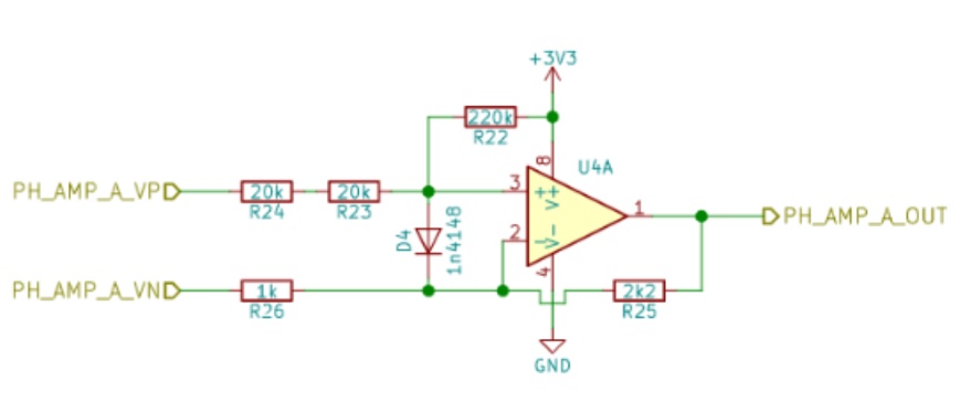
after a small computation I can say that … this schematic is weird.
‘cause , there is also a shunt resistor ( 3.5mR) used to measure currents from ALL 1/2H bridges … these shunt voltage as amplified by following schematic :
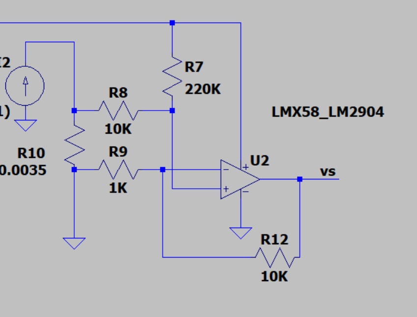
it isn’t negleable…
I don’t know what are the impact for that into the simplefoc lib, even don’t know if it is usefull.
with the above value, with zero current in shunt, offset output is 1.57V (1.59V by simulation) , and gain is 0.036V by A (0.037 by simulation)
should I, to be effective, short the latter shunt to avoid disturbance into simplefoc algo?
best regards
I’m sorry to say but the library does not support single shunt current sensing. You need a minimum of 2 shunts on seperate phases, and better if you have 3 shunts, one for each phase…
I think maybe we discussed these pics on discord?
Hi
I’m OoH for a while.
thx for your interest
best regards
Hi Runger,
I do have 3 current measument features, not shunts preciselly because it is the Rdson .
It is a low cost implementation, gambling on the mosfet RdsOn stability .
the cons is … the ADC sample and hold must be triggered during on time with a small blanking to avoid switching ringing .
what is your proposal on discord?
best regards