I was finally able to get a clean PWM low voltage signal out of the driver.
I found a few small errors that prevented me originally from getting results, due to me cutting too many corners when designing the board. Eventually I was able to contact an on-semi engineer who pointed out the biggest problem, which was really easy to solve, I had to connect the over-current sense to ground via 100R to bring it to 0.4V because I didn’t use a current sense shunt for proper sensing. RTFM. Apparently the board MUST use a current sense resistor as an integral component, else the logic cuts off the low power side to prevent an apparent overload. Originally I left that open which apparently brought the CIN high and shut it down. I also had a few incorrect values of the zenner diodes, but that was pure fat-finger when I picked the components.
Anyway I will try to post later more results when I load the driver with high current. The driver works just fine with low voltage, and the on-semi engineer confirmed low voltage for that board is perfectly fine, so my plan is to use a power-dissipation resistor to test 10A current at 15 volts before we graduate the board to driving a low amps low voltage servo motor which will be the ultimate test because as @runger pointed out at low power and static PWM the circuit may not charge the high side capacitors to trigger.
Edit: The power resistor is working fine, the driver maintains output, will move to driving a motor.
Edit2: The motor works. I am using a 1kw motor at 1kHz PWM. The driver gets really hot, I am running without a heatsink and the mode of operation is really inefficient so a lot of heat is generated. Also the trigger capacitors are too large for lower PWM and the 1kHz noise is a bit too much.
Conclusion: The driver works fine. Next steps are to prepare a real board with smaller high side capacitors suitable for 10 to 15kHz PWM and shunts and a heatsink and everything. And re-read the datasheet in case I missed anything
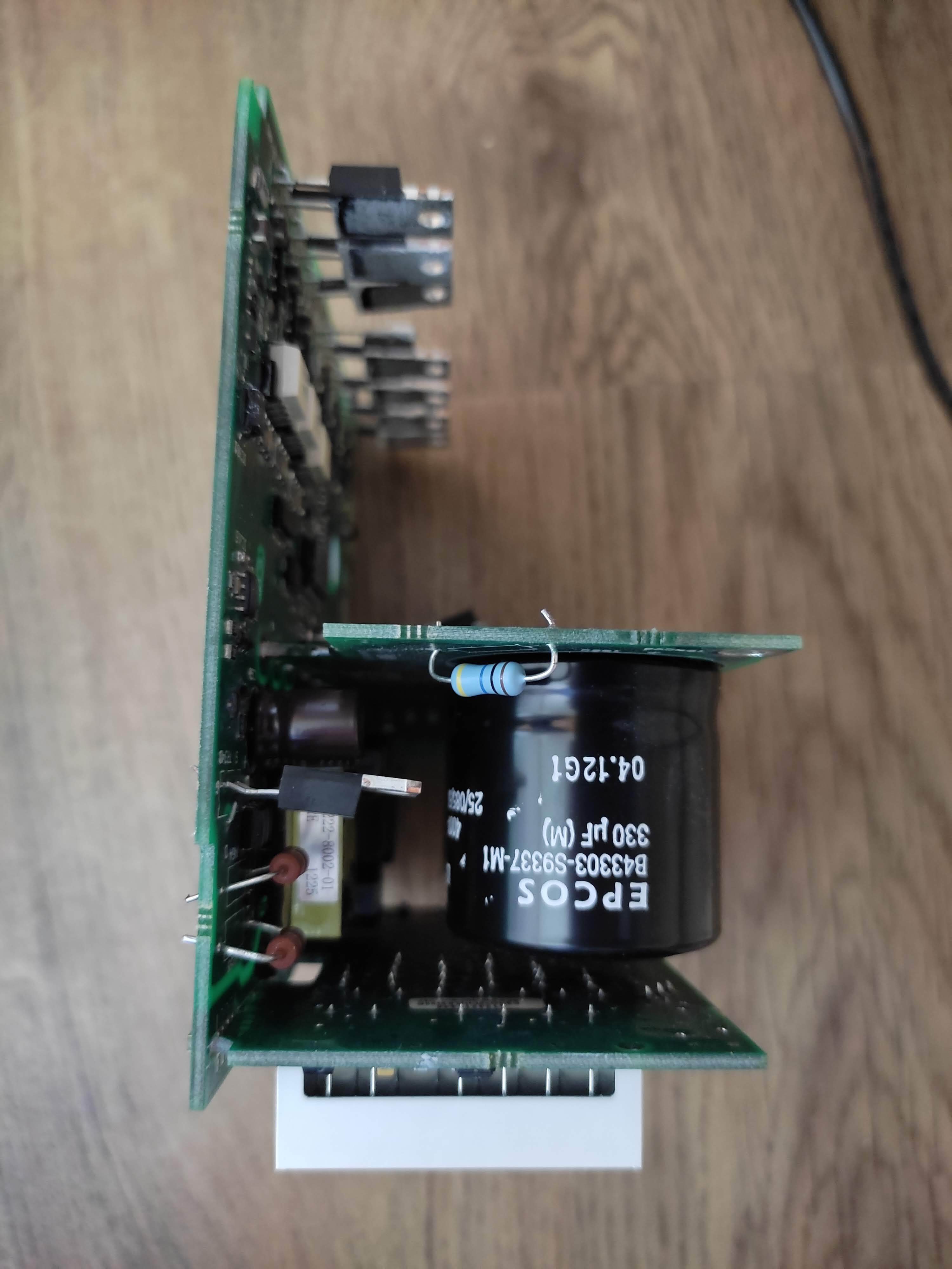
Here is a pic of the setup. Notice I am using the same supply for the logic and power, a really bad idea.
Good, that it’s working, I ordered the parts I think I need and now doing the circuit diagram. Atm I’m aiming for a complete module that you can mount to a din rail.
Tomorrow I’m taking apart a Emerson vfd with breaking resistor to look how they do the breaking resistor and voltage measuring of the DC bus.
That’s very interesting. Adding the ability to brake and dissipate the power and control it from the software is a very important feature IMO. ODrive can do that, but I am not touching odrive. However before the software, we need to figure out the braking circuit.
I used a odrive before (i had a clone).
With a firmware update they locked the clones out essentially, also the 3.6 board schematics aren’t open source anymore, and the configuration was honestly just shit, tool me like 5 hours to get a motor spinning. (Simplefoc took like 30 minutes)
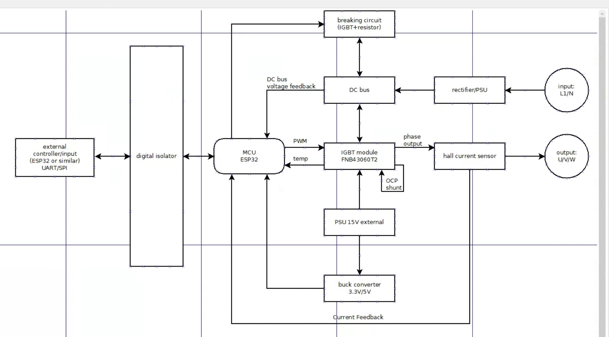
My current thinking for the breaking circuit is to just use a voltage divider on the DC bus with 10 resistors in series (for good isolation) to get 3.3v signal straight into the adc pin of the esp 32. And across the DC bus a igbt with a breaking resistor in series. But I’m interested how it’s actually done in the industrial vfd.
I am not familiar and have not researched braking, and from the picture above I cannot tell, I will need a real schematics.
My understanding of how braking works, you disable the high and low side which forces the motor to keep spinning due to momentum (say you roll on a scooter downhill). When you disable the high and low side, the low side diode starts shunting the energy from the motor and if you at that time, simultaneously, turn on a braking circuit involving a power dissipation resistor connected in parallel with the low side diode (i.e. phase output and ground) the power resistor will shunt the energy and dissipate as heat.
This is my primitive understanding below for one of the phases.
Edit: Of course you also need to solve for the high side in case the motor is turning the other direction, and disconnect VS and redirect the high side into the shunt which is extra circuitry.
What do you think? should I isolate the MCU from the igbt or should I run it like i have drawn it in the block diagram and just isolate the inputs outputs to the board.
Due to the extreme voltage and currents in a production IGBT circuit the MCU must be isolated, preferably optoisolation which galvanically separates the MCU. Optoisolators are really expensive especially when you need high frequency or ratiometric response, as in analog in / analog out. If you avoid analog signals and work only PWM and sensors with digital protocols, optoisolation modules are pretty standard. This will however add to the size and cost of the board.
Isolating the 6 pwm signals isn’t a problem, but the ntc signal and DC bus voltage signal are a bit complicated.
In The typical application circuit for the igbt module the mcu isn’t isolated, and it was the same in the Chinese vfd i took apart and it works fine. Only the Emerson one has the MCU isolated. The Chinese vfd has isolators for the external inputs/outputs.
I have never done optoisolation, this is only from what I have discussed with colleagues. There is a reason why the cheap boards don’t have it, its expensive and adds to the circuit. The Toshiba TLP2372 20Mbps Photocoupler is $2 per channel, so for 20 channels to isolate a small MCU that’s easy $40 extra. Also that’s why Emerson does it, their name and quality commitment is more important that $40.
Originally i wanted to use them to isolate the external inputs/outputs, but I think I can also put them between the MCU and igbt module, for the 6 pwm signals.
Yes, that’s basically how it works but he doesn’t tell you how that mystery logic box is constructed to sense the freewheeling reverse voltage change to turn on the braking resistor circuit…
I think it’s easy, but it’s possible that i think to easy.
My thinking would be to monitor the DC bus voltage. Say normally it’s at 200v, so when decelerating the voltage rises to 230v or whatever. Just have the mcu monitor the DC bus voltage and say if the voltage rises over 205v it starts to put pwm signal to the igbt across the DC bus to burn some of the energy to get it back down to 200v.
Edit: for voltage sensing just a voltage divider with appropriate rated resistors since the MCU is referenced to the DC bus anyway.
Perhaps. You will need a dependency logic between the VDelta = (Vin - VOver), to turn the chopper between 0 and 100%. Say 10% for every 10v over? So if the voltage goes to 300V you open the brake 100%?