How to create an MCU switch to disconnect/connect a 3 phase BLDC motor from a driver, at the driver's output?

Hi… my question and problem has nothing to do with FOC, actually, but If someone can point me how to find a solution it would be great…

I need a way to connect/disconnect a 3 phase BLDC motor from the A, B and C output terminals of a BLDC Sensorless (BACK_EMF) driver. I don’t have access to mod the driver, so the only access point I’ve got it’s the A, B and C terminals that connect to the motor. I’ll add an extra MCU to control the “connecting” or “disconnecting” the motor from the driver.

The reason I want to do this is that I want to have two equal motors, connected to the same one driver, but only one motor will be on at a time. When using one, the other will be “disconnected”, and vice-versa.

My motors runs at 36VDC, at 1A, and at peak, at 3A the driver protects it and stops the motor. The frequency the driver outtputs, in pwm at each phase is variable. At low speeds it’s slower, but it’s no more than 30KHz at max speed.

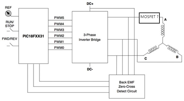
I was thinking that I needed three mosfets, one for each phase, connected between each output of the driver (A,B or C) to each winding of the motor. And f I turned off the three mosfets the motor would be disconnected, and if It I turned on the three mosfets the motor would be connected to the driver and allowed to work, like in the picture below:

Mosfet

The commutation for the sensorless back-EMF BLDC is a 6 step trapezoidal sequence. So the current moves both ways in the three windings, correct?

So simple mosfets would allow current in one way only, not the other direction, right?

So I could use three ordinary relays, each on each phase right? But I wanted to avoid relays. But if a relay was used, would this fast switching back and forth of the current cause any trouble on the commutation sequence? Noise? Some other problems?

Relay

Then I was researching, and it seems that I need some kind of bidirectional mosfet switch. And It could be done with P or N mosfets. It seems that with N mosfet it would be better in terms of having a low RdsON, less heat, smaller size.

I was reading about this bi-directional switch here: https://www.homemade-circuits.com/bidirectional-switch/

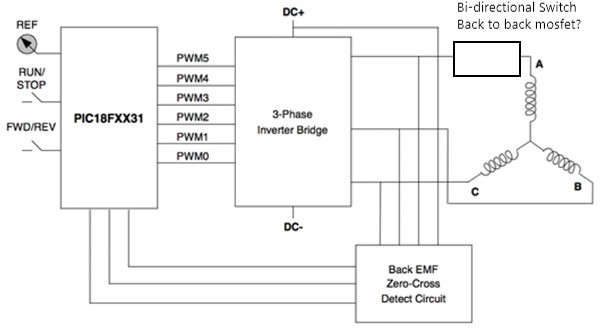
Something like in the picture below:

Discrete-Implementation-of-BPS-Using-N-MOSFETs

So I would need one circuit like this above for each output of the driver, for each motor

The marked in blue A would be one of the outputs of the driver and B would be the corresponding winding of the motor.

So… would I need three of these set-ups for each motor? Would it work? When a motor is in the “connected state”, would the fast back-and forth current switching of the 6 step commutation work as there were a direct connection between the driver and the motor’s windings? Would the motor work normally?

Bi-directional Switch - back to back Mosfet

Or… would there be a better and simpler solution?

Thanks!

Rodrigo

I would use relays for this to avoid design complexity. It should not introduce as many problems as you are thinking. The important thing would be that the relays are not directly next to the motor (avoiding stray field if using normal relays). The better thing would be an SSR but these can be quite more expensive depending on the voltage/current you are planning to use.

Thanks!

The relays won’t be close to the motor.

But I prefer to use SSRs, then. But again, I need an AC SSR right? That allow current to flow in both ways in each phase, correct? The DC (output) SSR won’t work, right?

Regards, Rodrigo

Yes, I think so, but I’m not 100% on this.

Well, so I had a SSR dual Module laying around, just the one below:

And I tested with my driver and motor, in just one of the driver output phase. I left the other two phases connected directly as intended.

And it didn’t work properly. The motor turned on and rotated, but not efficiently, and making some noise…

So, this kind of AC SSR won’t work. Those bigger ones I I guess won’t work either, because they are rated at min 90-480VAC, and my motor/driver are rated at max 36V.

Any other ideas?

Hi,

I would not use relays, to be honest. You would have to find some that can handle the load (not a problem per se, but they will be large components), and it will cause extra costs.
But it can work.

You could add MOSFET based switches, like you describe. You will need 2 FETs back to back to prevent current flowing in both directions through the body diodes.
So this would mean you have to add 6 FETs… to switch them, you should use N-FETs and will need bootstrapping to switch them with a voltage higher than the drive voltage.

But since you are adding 6 FETs anyways in this scenario, have you considered just putting 2 drivers on the board, and using the 6 FETs in a normal 3-phase configuration for the second motor?
If you don’t have enough MCU pins for the second motor, you could choose a driver with disable input, and connect the same MCU pins to both drivers, and only enable one at a time?

but isn’t this just the same as an SSR, at least in theory?

Sure, except SSRs are much bigger - due to integrated heat-sinks, etc… also you’d probably have to take one without zero-crossing detection.

But if you use a SSR instead of a mechanical relay, the solution becomes a lot like using back-to-back FETs in the phase leads.

But really I like my suggestion of the second driver much better :slight_smile:

Thanks for your answers!

What kind of driver it would be? Could I add it to the output of the original driver?

I can’t mess with the original PCB… It has an LCD attached, touch buttons, small laser etched MCUs, it’s ready made… so I can’t risk modifying it and burning it…

I only have access to the A,B and C outputs of it… Could this extra-driver be put in the output of my original driver? If so, can you give an example, or model? I can add an external MCU to control it, but can’t mess with the original PCB…

Rodrigo

No, if you can’t modify the PCB, then your idea with the MOSFET switches, perhaps in the form of “SSRs” like vipqualitypost suggests, is probably the way to go.

But it is a very strange setup, you’ll have to account for it on the software side with very strange code. Perhaps you could do something like initialize one instance of BLDCDriver, and link it to two instances of BLDCMotor. Then when switching between them, you would stop calling the loopFOC() and move() on the one motor, switch over the phase wires, and start calling loopFOC() and move() on the other motor.

You’d have to pay attention to keep calling sensor.update() on the first motor, or you might miss full rotations if the motor is still moving, or moved externally. and there would probably be issues due to the large time-gap after switching - the PID might need to be reset as well.

On your SSRs it says 240V 50/60Hz. This may be an important limitation here. I have l no idea how ab SSR will behave at other (much higher) frequencies as used here.

Maybe the mechanical relays are really a better solution here, as it’s just a metal spring contact?

Many SSRs designed for operation in the power network have a zero crossing detection- they switch on the next zero crossing of the AC power. They may not work well in this application.

Others may have a fairly high RDSon compared to the motor phase resistance?

How quickly do you switch between the motors?

@VIPQualityPost I indeed tested one of the phases with a single mechanical relay and didn’t notice anything different in terms of noise and speed, in the lowest and highest speed settings. So I guess six relays, three for each motor, or a pcb ready with relays like this below, would definitely work.

But I still would like a more… silent option, if it’s possible… If not, I’d go for the relays…

@runger @VIPQualityPost I believe my SSR didn’t work maybe because there’s internally some zero crossing detection… or maybe a too high voltage range alowed…

I’d like to give it a try with a more simple dual N-Mosfets configuration, back to back, with some external supply to give 12V to the gate…

Do you think this is a correct “hardware” setup for testing it? I isolated the MCU and used a second separate supply to drive the mosfets gate at 12V… I’ll use a single unit for testing just one phase, not the three at the same time as in the simulation and diagram…

This is the link for the simulation in Falstad: https://tinyurl.com/yo82tngr

Thanks!

Most relays you can connect both “NO” normally open and “NC” normally closed. If you don’t need a state where both motors are fully disconnected, you can do this with 3 relays, by connecting them so in one state, one motor is fully connected, and the other state the other motor.

I think this drawing makes sense but for both motors, won’t you need another set of 6?

That’s it!! I don’t need both disconnected! Either one or the other is on while the other is off. So, if relays are to be used, 3 relays solve the problem!

Sure, this configuration is for one motor only… I’ll need 6 more mosfets, and another opto. I’ll do some testing with this option in a single phase on a single motor, but I’m leaning towards relays now… seems much simpler to implement…

Thanks!

1 Like

Hmmmm… couldn’t you get by with just 6 FETs for both motors?

If you connect them drain to drain, power via the drains, and the motor phases to the sources?

Hmmm… could you elaborate on that? Or draw a quick schematics just for me to see how to connect them all?? And how to disconnect them… I can’t figure it out…

Regards, Rodrigo

@VIPQualityPost and @runger just to add to this topic, as a proof of concept, the two back to back N-mosfets, connected at each other by their sources, as I’ve shown in post #14, worked perfectly at any speed. I tested with only one phase, while the others were directly connected to the driver. So I guess this 6 mosfets for each motor (12 in total) would work also, as the 3 mechanical relays only also would (in my case).

I meant something like this:

These are N-FETs, so you’d switch them with a gate voltage higher than the maximum phase voltage.