is this using body diode to conduct when current is leaving phase?
No because you’d expect Q1 to be conducting whenever motor 1 is operating.
It would only be after the switch to the second motor, if the first one still was moving or something that the body diode would conduct.
Hi…
Am I doing something wrong? I’m trying to simulate in Falstad your schematics setup but it’s not working in the sim as intended… Want to check it out? Should I change anything?
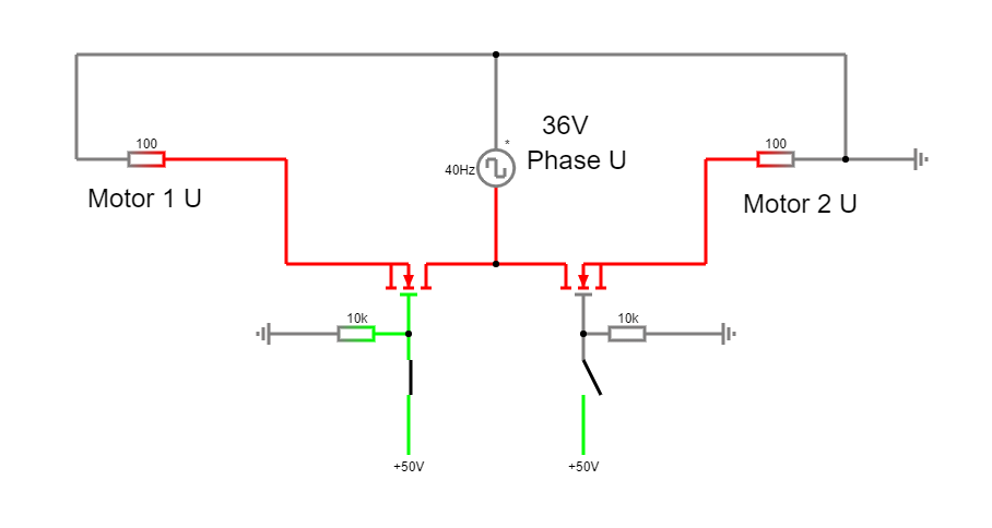
The falstad online sim is here: https://tinyurl.com/yw7l322u
Hey,
Please excuse my bad drawing:
Not sure its the best idea, but it does kind of look like it works to me…
Hi!
I´ve checked your falstad sim!
But… doesn´t the current has to flow in both ways through the windings of the motor? One cycle it goes “forward” and in another it goes “backward”? Or is it always in the same direction, like DC?
Because in your sim the current flows in each motor only in one direction. In the other direction the current stops flowing. Is it correct?
Ah… the mosfets were not corrected drain to drain, as you previously said. So I corrected you sim… Check it out… But still, current only flows in one direction…
Regards, Rodrigo
I think they were connected drain to drain, just my drawing is not as neat as yours, I didn’t “mirror” the second FET to make the drawing neat. But if you look more closely, you’ll see they are the same circuit?
Yes, the current will flow both ways, depending on whether the phase is connected to power or to ground.
But this simulation only has a square wave voltage source on a single phase, so where would the power come from flowing in the other direction? If you want to see this you will need a more complete simulation, with a second (and third) phase which is also receiving power…
Like this you’re only simulating the switching behavior of a single phase…
Indeed! My mistake! I’ve been using Falstad for a long time, so it’s easier for me to draw there… that’s why it looks… neat … ![]()
I’ll try to build a partial circuit for one phase only to check it working and I’ll post it back here!!
And also a complete 3 phase simulation also to see how it works on screen!
Thanks!
Hi!
I’m assembling the test project with the three relays… but… I have one doubt…
Could I use just two relays?
I could leave one phase, let’s say “A”, always connected to the driver’s “A” output and to both motors “A” phases…
And then one relay for B phase and another for C phase.
So if both relays are set to NO, for instance, only the first motor would have the three windings connected to the driver ( “A” always connected and “B” and “C” connected through the relays) and the second motor would have always one winding connected to the driver (“A” winding), but the other two would be disconnected (Relays for B and C phases), so effectively the second motor wouldn’t turn, current wouldn’t flow nowhere in the second motor because only one wire would be connected through it.
Diagram below:
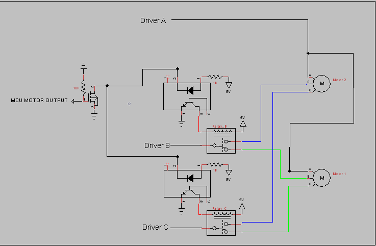
Does this make sense? Is that correct?
Regards, Rodrigo