Thanks for the hint ![]()
Hey no problem - if you’re on discord I’m also happy to jump on a chat if you want to discuss anything. We’re very appreciative if anyone wants to undertake such a difficult task, so happy to support!
The basic operating principle of the PWM drivers is that the _configureXY methods return a void* to a hardware-specific struct. You can put in in whatever you like and need for the GD32, but typically it contains references to the timers and channels used, etc…
the _configureXY methods are supposed to make sure the pins used make sense, make sure the timers/pins aren’t being used more than once, etc… Then they initialise the timers, sometimes this also involves setting up the clocks that drive the timers.
Finally they create and fill the driver-specific struct and return a pointer to it.
If at any point they fail, they should clean up as best they can, and return the error constant. They can make use of SimpleFOCDebug::println() to inform the user what when wrong.
the _setDutyCycleXY methods are called to change the duty cycle or set the phases to hi Z mode. They should be implemented as efficiently as possible and should never print to serial port or things like this.
In terms of PWM, the object is provide the most control over the frequency as the hardware allows, ideally from 1Hz to 200kHz ![]() if the hardware can’t do it, we take whatever the hardware can do. The SimpleDC library can use low PWM frequencies, the SimpleFOC library uses 2kHz - 100kHz realistically for BLDC driving, with 22 - 40kHz being the most used ranges.
if the hardware can’t do it, we take whatever the hardware can do. The SimpleDC library can use low PWM frequencies, the SimpleFOC library uses 2kHz - 100kHz realistically for BLDC driving, with 22 - 40kHz being the most used ranges.
For a given PWM frequency, the hardware should be configured to give the highest resolution it can, e.g. generally this means setting the clocks as fast as they can go.
PWM should be configured in “phase correct” or “centre-aligned” mode. Sometimes this is also called “up-down counting” mode. In this mode the timers count up to the top, and down again, switching on as they pass the compare value upwards and off as they pass it downwards. This leads to PWM signals that have the on-time “centred” in their periods, and this is important for low-side current sensing.
In terms of 6-PWM there is extra complexity: dead-time insertion.
Some MCUs can do it in hardware, some can do it, but only for very specific pins (e.g. STM32) and others can’t do it at all. If GD32 offers it, it would be good to support it.
Where not supported due to hardware or bad pin choices, the 6-PWM driver should support software dead-time insertion. This can only work if the PWM is centre aligned and all pins are driven by timers that are synchronised (same PWM frequency and started concurrently).
Furthermore the 6-PWM driver should support setting Hi-Z mode by checking the phase state and setting the FETs accordingly.
Really, if there are any questions, please let me know. You can also feel free to DM me.
This is a very very very initial commit just to make sure I go in the right direction.
@robca we can collaborate on this offline if you are interested
Definately looks like the right direction given you’re targeting only 6-PWM for the moment.
Does it have to be TIMER0 or could one configure 6-PWM on other timers as well?
Yes timer0 is the advanced timer that has complementary channels and deadtime insertion. But I can look at software 6pwm and other pwms later.
We would need to improve arduino-gd32 for that as well
It works but I need to do more tests.
3 Likes
Hi,
The development was in standby as I was in holidays for 2 weeks.
The driver seems to work fine, but as I am new with simpleFOC, there are things I don’t understand.
If I set driver.voltage_power_supply, driver.voltage_limit and moto.voltage_limit to 16V, I was assuming that in pure voltage mode, I could set a target of 16V. But it seems anything above 8V is just clipped because it’s added to center here?
[EDIT] Nevermind, I missed this
Ok, so its all clear?
You really want
motor.voltage_limit = driver.voltage_limit / 2.0f;
This is because they act in different coordinate spaces - the motor limit acts on the D/Q axis vector while the driver limit is an absolute limit referenced to GND.
I find it a bit confusing but now It’s clear why higher target was resulting in more noise and lower speed ![]()
Thank you, I will also include this parameter.
When I will work on the current sensing, I should then reduce driver.voltage_limit to allow a minimum of low side ON time for the sampling of 2 currents with a single adc.
One thing I saw is that simpleFOC is using driver.voltage_limit/2 for centering the modulation, which is not 50% if driver.voltage_power_supply > driver.voltage_limit.
I think it’s good practice to center at 50% to balance the low side and high side.
Have you guys ever thought about it ?
Sorry if I ask too many questions ![]()
[EDIT] One of the places where I saw a mention about that
And this from here:

Very astute, yes, this is an elegant way to do it. Of course it comes at the price of limiting your maximum torque a little (depending on the motor).
Actually personally I did not. Maybe Antun did. Perhaps we should add it as an option? Or replace the current scheme with what you suggest. Or perhaps we should introduce an offset to allow the user to choose the mid-point if desired, and default it to driver.voltage_limit/2 (the current method)?
I will discuss it with @Antun_Skuric
From my experience, current samples are bad at high duty cycle.
Some FOC implementations just sample the two best phase currents (lowest duty cycles), and calculate the third one, but it’s not possible with only 2 shunts.
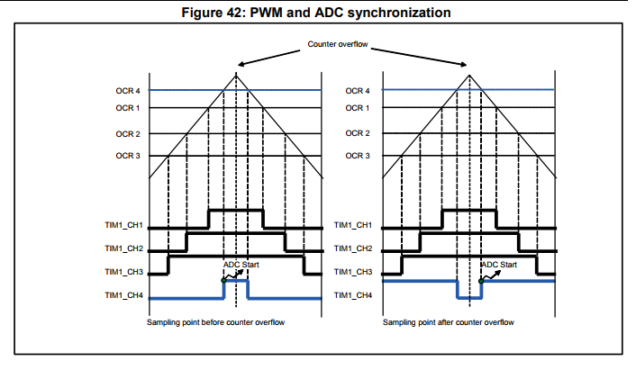
Another thing I will do is using the 4th timer channel to trigger injected adc after the middle of the pwm period, to account for the turn on time and noise. This also helps at high duty cycle. I also have an STM32 example of this, I can share it if you are interested.
Hey,
I think if you set TIMx_RCR = 1 you’ll get a timer update event on underflows only.
If I’m not wrong the underflow or zero turnaround point should correspond to the middle of the low side on period.
In this way you don’t need to maintain and update a fourth timer channel.
The update event can be routed to the timer trigger out signal (TRGO or TRGO2) and used to directly trigger the ADC via the event system.
The exact mechanics depend a bit on the chip you’re using. Is this still the gigadevices MCU? Does it even have the same triggers and timers as the STM32s?
Hey guys,
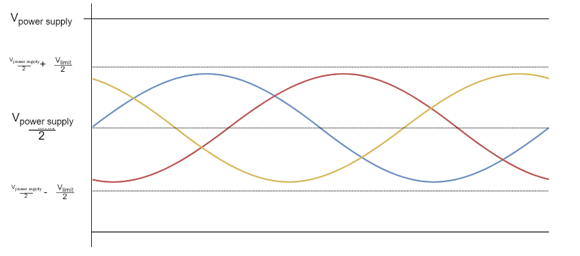
So driver.voltage_limit is the maximum DC voltage (maximum duty cycle) that you do not want to surpass using your driver. If we would center the modulation at the half of the power supply, that might already be higher that the driver.voltage_limit, in the worst case. If driver.voltage_limit is just a bitlower than the power supply voltage then centering around half of the power supply would not be in the center of the range and pozitive peaks would start to be saturated much before the negative ones.
So driver.voltage_limit is not limiting the voltage vector but the power supply voltage.
On the other hand, the variable limiting the voltage vector is motor.voltage_limit. If you set the motor.voltzge_limit then the centerin will not be influenced but the relative voltage between the phases will be limited (the voltage vector).
GD32F130 can use Timer 0 Channel 3 as trigger source for Inserted ADC (e.g. here ).
STM32F103 can use Timer 1/8 Channel 4 as trigger for the Injected ADC (e.g. here )
That’s useful if you want to trigger the ADC before of after the middle
You have a enable the channel, set it’s pulse (not 0 otherwise it overlaps with the timer update), and set PWM0 or PWM1 depending on if you want to start before or after the middle.
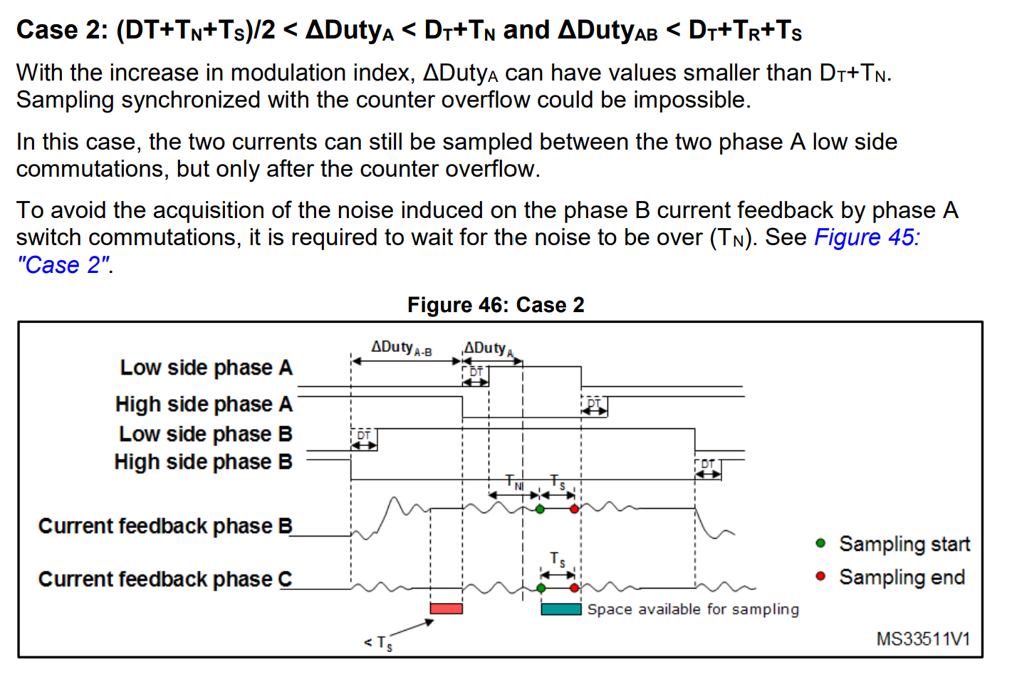
STM32 is using this in their MCSDK to sample after the Deadtime + Rise + Noise;
Sorry that might deserve a separate thread.
That is how it works if you set your driver.voltage_limit to
driver.voltage_limit = driver.voltage_power_supply
And you use your motor.voltage_limit to limit the phase voltages.
So here is the full diagram of the limits:

Thanks Antun.
I will use motor.voltage_limit and make sure the maximum target I set will not be clipped here
Some more progress.
Current sensing is working (and smoothing sensor).
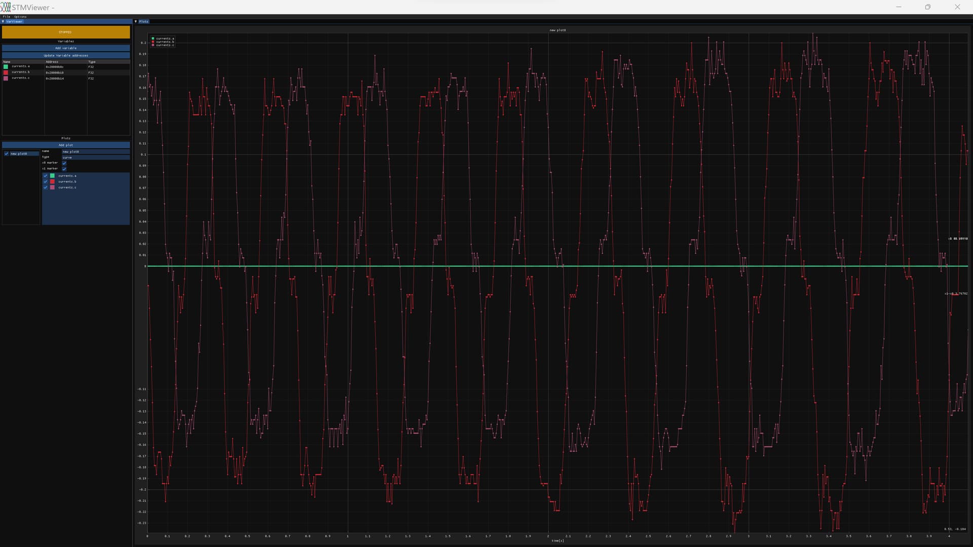
DriverAlign fails for some reason but if I skip it I can use FOC current mode.

2 Likes
I just gotta say the technical knowledge and skill and background that comes to the fore here is amazing. But it’s still in aid of getting this one board working, which is not a particularly suitable board for many purposes… Which says to me that much of the skill and time being poured in may have little result for others down the line. In contrast to working on the QUADVRANS (sp?) or whatever, a board built from the ground up to be powerful, economical, compatible, and -ultimately- suitable on * all* counts.
I could have just ported Eferu’s FOC firmware to those boards, but I decided to implement SimpleFOC drivers for GD32 chips because simpleFOC has a great community and good contributors.
I hope I can then help make SimpleFOC better ( e.g. improving hall sensor support, helping with dual foc, deadtime compensation), rather than working in a silo on my own firmware.
Making boards is not my thing, I can’t really help there sorry.
I can only help with the software.