Hi @runger
Thank you for your message and the explanation, it makes sense with the pulse value and I now understand it ![]()
I’ll try the SPI later today and see if there is any luck ![]()
Hi @runger Thank you for your message…
Okay, I think I will give ESP 32 a try. I was not aware that I could run those with Arduino code in the Arduino environment. I will give it a try and I am excited to see the result
I have seen there are various kind of ESP 32 on Amazon.
https://www.amazon.de/-/en/AZDelivery-Unsoldered-Development-successor-compatible/dp/B0BFDL7W6N/ref=sr_1_4?crid=1ZMSYA961WDR8&keywords=esp%2B32&qid=1669019595&sprefix=esp%2B32%2Caps%2C108&sr=8-4&th=1
E.g. I can buy them with CP2102 or CH340… Not quite sure what the differences are and if they are important in my project?
BR, Jesper
Looks like it should work!
Like you say, there is a bewildering array of ESP32 modules, and even more independent boards made with them, so it is hard to choose.
All of the ESP32s should work, but the ESP32s that have a “MCPWM” Unit are much better for doing motor control. That is most of them, but not, for example, the new ESP32 C3.
So problem #1 is identifying which module is actually being used on the boards, and then problem #2 is checking against the ESP32 datasheet for that module that it includes the MCPWM unit.
In terms of CP2102 or CH340 I don’t think it matters. Its the type of Serial to USB converter that is on the board, but I believe they are all supported by current versions of Windows or Mac OS.
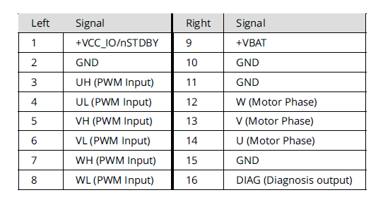
Ok, super, so I supply the TMC6300 with 5 V at the vbat (pin 9)?
And then 3.3 V to Pin1 VCC_IO? I though they needed to be supplied with 5V because the GPIO pin from Arduino sends out 5v?
Hey guys,
The MagneticPWM sensor is really the worst supported one. ![]()
However, it works much better in interrupt based implementation than in blocking one. In your code @JesperSondergaard you’ve used the blocking one, you can find out a bit more about it in the docs : Magnetic sensor PWM | Arduino-FOC
but basically the blocking one used puleIn function that has pretty bad resolution and it is only intended to be used if every other way is not possible.
So please consider using pin 2 of your arduino as encoder_J and after senor.init() call sensor.attachInterrupt()
Here is an example code from the docs:
#include <SimpleFOC.h>

// MagneticSensorPWM(uint8_t _pinPWM, int _min, int _max)
// - _pinPWM:         the pin that is reading the pwm from magnetic sensor
// - _min_raw_count:  the minimal length of the pulse (in microseconds)
// - _max_raw_count:  the maximal length of the pulse (in microseconds)
MagneticSensorPWM sensor = MagneticSensorPWM(2, 4, 904);
void doPWM(){sensor.handlePWM();}

void setup() {
  // monitoring port
  Serial.begin(115200);

  // initialise magnetic sensor hardware
  sensor.init();
  // comment out to use sensor in blocking (non-interrupt) way
  sensor.enableInterrupt(doPWM);

  Serial.println("Sensor ready");
  _delay(1000);
}

void loop() {
  // IMPORTANT - call as frequently as possible
  // update the sensor values
  sensor.update();
  // display the angle and the angular velocity to the terminal
  Serial.print(sensor.getAngle());
  Serial.print("\t");
  Serial.println(sensor.getVelocity());
}
But even with thhis approach you’ll still be far better off if you’d just use SPI.
Regarding the duty cycle:
The constructor of the MagneticSensorPWM class takes as an argument the value of microseconds of the shortest and the longest pulse duration, not the duty cycle values from the datasheet. Because different sensors have different PWM frequencies. And AS5048 usually has a frequency of 1kHz. The duty cycle is has 4119 discrete timesteps as you’ve seen. But these steps are all within 1ms. So that’s why the min value is a few microseconds and max value is almost 1 miliseconds (1000us).
Yes corret you supply 5V to +VBAT from your bench supply.
And +VCC_IO between 1.8-5V (i initially said 3.3 as i assumed its what coming out of arduino),
Important is that you hook up VCC_IO and GND to your MCU. Sometimes TMC have some irradical behavior if there is no common ground with MCU.
You will notice that without +VCC the blue PWR diode is dimmed or it flash/flutter as PWM signal goes to BOB, once you hook up VCC and GND to MCU the diode will light up and stop flutter.
Hi @runger
I tried to connect my MKRWIFI 1010 to the setup with these pins,
But I do not get any message in the console, that I can type a value? It is as if the code does not work correct on the board? Is the MKR wifi 1010 supported in the FOC?
If I switched the pins to my normal arduino UNO setup and then everything worked fine again?
Code is like this
// Open loop motor control example
#include <SimpleFOC.h>
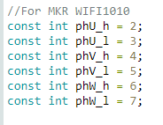
//For MKR WIFI1010
const int phU_h = 2;
const int phU_l = 3;
const int phV_h = 4;
const int phV_l = 5;
const int phW_h = 6;
const int phW_l = 7;
// BLDC motor & driver instance
// BLDCMotor( pp number , phase resistance)
BLDCMotor motor = BLDCMotor(11);
BLDCDriver6PWM driver = BLDCDriver6PWM(phU_h,phU_l, phV_h,phV_l, phW_h,phW_l);
// instantiate the commander
Commander command = Commander(Serial);
void doTarget(char* cmd) { command.scalar(&motor.target, cmd); }
void setup() {
pinMode(phU_h, OUTPUT);
pinMode(phU_l, OUTPUT);
pinMode(phV_h, OUTPUT);
pinMode(phV_l, OUTPUT);
pinMode(phW_h, OUTPUT);
pinMode(phW_l, OUTPUT);
// Serial.begin(115200);
Serial.begin(9600);
// driver config
// power supply voltage [V]
driver.voltage_power_supply = 8;
driver.init();
// link the motor and the driver
motor.linkDriver(&driver);
// limiting motor movements
motor.voltage_limit = 3; // [V] - if phase resistance not defined
motor.velocity_limit = 5; // [rad/s] cca 50rpm
// open loop control config
motor.controller = MotionControlType::velocity_openloop;
// init motor hardware
motor.init();
motor.initFOC();
// add target command T
command.add('T', doTarget, "target velocity");
Serial.println("Motor ready!");
Serial.println("Set target velocity [rad/s]");
_delay(1000);
}
void loop() {
motor.loopFOC();
// open loop velocity movement
// using motor.voltage_limit and motor.velocity_limit
motor.move();
// user communication
command.run();
}
type or paste code here
Die Funktion motor. move ist bei dir leer. So muss es nicht sein.
It’s ok to leave out the parameter to motor.move() - then it will use whatever is set as motor.target from before. So if you’re using commander to se the target values, you don’t have to pass them.
MKR1010 should work. But you have to use the right pins. I have to check if I can find a sample program in my collection when I get to my workshop.
Try adding a SimpleFOCDebug::enable() to the beginning of your setup, after the Serial.begin()
Then you should see some debug output regarding which pins are being used.
So I think it should be:
As Arduino pins:
Phase 1 high: A3 low: 0
Phase 2 high: A4 low: 1
Phase 3 high: 2 low: 6
As MCU pins:
Phase 1 high: PA4 low: PA22
Phase 2 high: PA5 low: PA23
Phase 3 high: PA10 low: PA20
Those pins also check out with the code.
There’s a few other combinations you can use if you don’t like those, but the SAMD21 is very fussy about its PWM pins. You have to use the right combination, and the right pins on high and low side for it to work.
Hi @runger , @Karl_Makes_Music, @Owen_Williams, @Valentine, @Antun_Skuric
So I know got the ESP32 connected and it works in open loop. I Can make the GM3506 motor spin around and also set an angle.
I am still struggling with the SPI when trying to get the AS5048A to work
I tried the simple code for getting the SPI to work, but the monitor just freaks out like this:

I dont know if it something with the connections on the AS5048?
I saw on a post that there has been som confusion about the wiring from it?
This is the post:
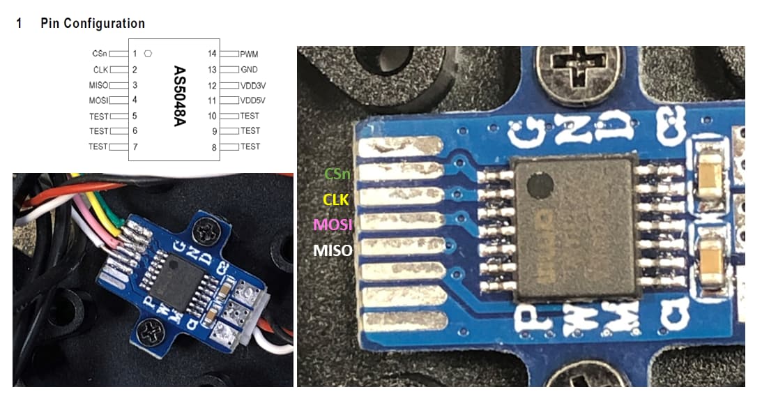
I connected
CC to SS pin 5
MISO to pin 23
CLK to pin 18
Also I supplied the AS5048A with 5V and GND


Here is the code:
#include <SimpleFOC.h>

* 1. List item

// MagneticSensorSPI(int cs, float _cpr, int _angle_register)
// cs              - SPI chip select pin
// bit_resolution  - sensor resolution
// angle_register  - (optional) angle read register - default 0x3FFF

MagneticSensorSPI AS5048 = MagneticSensorSPI(5, 14, 0x3FFF);

void setup() {
  // monitoring port
  Serial.begin(9600);

  // initialise magnetic sensor hardware
  AS5048.init();

  Serial.println("AS5048 ready");
  _delay(1000);
}

void loop() {
  // IMPORTANT - call as frequently as possible
  // update the sensor values
  AS5048.update();
  // display the angle and the angular velocity to the terminal
  Serial.print(AS5048.getAngle());
  Serial.print("\t");
  Serial.println(AS5048.getVelocity());
}
Hi Jesper,
Your read out from AS5048 seem normal, the right side column value you get is velocity, you probably want to enable some basic filtering (LPF) of signal so it doesnt pick up any unnecessary noise eg.
On the video i cant tell whether angle value changes while you rotate it or you getting some abstract values even if motor position is at idle.
Also try to run your serial monitor at 11520 instead of 9600.
I would also suggest to double and triple check your SPI wires, i see you are using them pluck in connectors, they often cause a problem, once i spent a week troubleshooting the problem, eventually finding out that issue was as simple as faulty wires.
Also if im not mistaken (someone correct me if im wrong), the AS5048x need both MISO and MOSI connected, i see you left out MOSI unconnected just now.
Edit:
Yupp seem MOSI is crucial for proper operation accroding to datasheet
(Sometimes, some sensors like MagAlpha does not need MOSI - unless you want to program it’s zero angle or change natural sensor direction)

If you unsure just pick up your multimeter and check continuity between 5th pad on the board and 3rd pin on the chip, probably via is under the pad or even under the IC
Of course, yes, great idea! It is connected like that with a via ![]()


Congrats on make it working:)
Your reading look right but you still get these Velocity spikes when in idle.
You could try lpf filtering to smooth out the noise.
motor.LPF_angle = LowPassFilter(0.02)
When you using it in closed loop.
In my case anything lower than 0.2 (with either as5600, maq430, or AS5048) actually make audible cool whine.
Depends on the motor and driver I guess.
I’m unsure why you have mangled output of serial monitor despite setting correct baudrate in your code and in monitor. I don’t use Arduino IDE (I remember it used give me wonky serial output, often frustrating).
Thanks @Karl_Makes_Music
So, I tried the code there was here:
Position control example code - Closed Loop
And the motor just spins like a baby ![]()
Here is my input from the monitor:
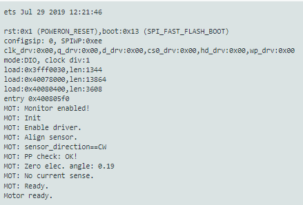
Here is a video of the show:

I had to put in 3.14/2 to make it spin a half turn, I would think I should have been just 3.12 for a half turn?
This is how my code looks:
#include <SimpleFOC.h>

const int phU_h = 32;
const int phU_l = 33;
const int phV_h = 25;
const int phV_l = 26;
const int phW_h = 27;
const int phW_l = 12;

// motor instance
BLDCMotor motor = BLDCMotor(11);
// driver instance
BLDCDriver6PWM driver = BLDCDriver6PWM(phU_h,phU_l, phV_h,phV_l, phW_h,phW_l);

MagneticSensorSPI sensor = MagneticSensorSPI(5, 14, 0x3FFF);

void setup() {

  pinMode(5, OUTPUT);
  pinMode(phU_h, OUTPUT);
  pinMode(phU_l, OUTPUT);
  pinMode(phV_h, OUTPUT);
  pinMode(phV_l, OUTPUT);
  pinMode(phW_h, OUTPUT);
  pinMode(phW_l, OUTPUT);

  // initialize encoder sensor hardware
  sensor.init();

  // link the motor to the sensor
  motor.linkSensor(&sensor);

  // driver config
  driver.init();
  motor.linkDriver(&driver);

  // set motion control loop to be used
  motor.controller = MotionControlType::angle;

  // controller configuration
  // default parameters in defaults.h

  // controller configuration based on the control type
  // velocity PID controller parameters
  // default P=0.5 I = 10 D =0
  motor.PID_velocity.P = 0.2;
  motor.PID_velocity.I = 20;
  motor.PID_velocity.D = 0.001;
  // jerk control using voltage voltage ramp
  // default value is 300 volts per sec  ~ 0.3V per millisecond
  motor.PID_velocity.output_ramp = 500;

  // velocity low pass filtering
  // default 5ms - try different values to see what is the best.
  // the lower the less filtered
  motor.LPF_velocity.Tf = 0.01;

  // angle P controller -  default P=20
  motor.P_angle.P = 20;

  //  maximal velocity of the position control
  // default 20
  motor.velocity_limit = 4;
  // default voltage_power_supply
  motor.voltage_limit = 8;

  // use monitoring with serial
  Serial.begin(115200);
  // comment out if not needed
  motor.useMonitoring(Serial);

  // initialize motor
  motor.init();
  // align encoder and start FOC
  motor.initFOC();


  Serial.println("Motor ready.");
  _delay(1000);
}

// angle set point variable
float target_angle = 3.14/2;
// timestamp for changing direction
long timestamp_us = _micros();

void loop() {

  // each one second
  if(_micros() - timestamp_us > 2e6) {
      timestamp_us = _micros();
      // inverse angle
      target_angle = -target_angle;
  }

  // main FOC algorithm function
  motor.loopFOC();

  // Motion control function
  motor.move(target_angle);
}
Since you’re using TMC6300 i’d suggest run it of 5-7V Supply and set driver voltage limit at around 4V.
3.14 for half turn is just about perfect, full rotation is at 6.28 Rads, with 3.14/2 you should get 90 deg rotation. This is strange indeed.
Since we’re on Haptic Textures topic and you got your setup working you might want to try this:
#include <SimpleFOC.h> // Call FOC Library
#include "util.h" // Call Utils Library


static const float DEAD_ZONE_DETENT_PERCENT = 0.2;
static const float DEAD_ZONE_RAD = 1 * _PI / 180;

static const float IDLE_VELOCITY_EWMA_ALPHA = 0.001;
static const float IDLE_VELOCITY_RAD_PER_SEC = 0.05;
static const uint32_t IDLE_CORRECTION_DELAY_MILLIS = 500;
static const float IDLE_CORRECTION_MAX_ANGLE_RAD = 5 * PI / 180;
static const float IDLE_CORRECTION_RATE_ALPHA = 0.0005;

const int phU_h = 32;
const int phU_l = 33;
const int phV_h = 25;
const int phV_l = 26;
const int phW_h = 27;
const int phW_l = 12;

BLDCMotor motor = BLDCMotor(11);
BLDCDriver6PWM driver = BLDCDriver6PWM(phU_h,phU_l, phV_h,phV_l, phW_h,phW_l);
MagneticSensorSPI sensor = MagneticSensorSPI(5, 14, 0x3FFF);


void setup(){

     sensor.init();
     motor.LPF_angle = LowPassFilter(0.02);
     motor.linkSensor(&sensor);

     driver.voltage_power_supply = 4;
     driver.voltage_limit = 2;
     driver.init();

     motor.linkDriver(&driver);

     // Set up motion control loop type
     motor.controller = MotionControlType::torque;

     motor.PID_velocity.P = 4;
     motor.PID_velocity.I = 0;
     motor.PID_velocity.D = 0.04;
     motor.PID_velocity.output_ramp = 10000;
     motor.PID_velocity.limit=10;

     // motor.LPF_velocity.Tf = 0.02;
     motor.velocity_limit = 10;
     motor.voltage_limit = 2.5;

     Serial.begin(115200);

     motor.init();
     motor.initFOC();


     Serial.println("Motor Initialized");
     delay(1000);

// }


 float idle_check_velocity_ewma = 0;
     uint32_t last_idle_start = 0;
     uint32_t last_debug = 0;
     uint32_t last_publish = 0;
     float current_detent_center = motor.shaft_angle;

   //Config 0
      int32_t num_positions = 256;
      int32_t position = 128;
      float position_width_radians = 3.75 * _PI / 180;
      float detent_strength_unit = 1.1;
      float endstop_strength_unit = 2;
      float snap_point = 1.1;
      char descriptor[50]  = "Fine Values 1.85degree";

//     //  //Config 1
//     // int32_t num_positions = 128;
//     // int32_t position = 64;
//     // float position_width_radians = 3.5 * _PI / 180;
//     // float detent_strength_unit = 0.9;
//     // float endstop_strength_unit = 1.2;
//     // float snap_point = 1.1;
//     // char descriptor[50]  = "Fine Values 1.85degree";

//     // // Config 2
//     int32_t num_positions = 2;
//     int32_t position = 0;
//     float position_width_radians = 30 * _PI / 180;
//     float detent_strength_unit = 9;
//     float endstop_strength_unit = 1;
//     float snap_point = 0.55;
//     char descriptor[50]  = "On/Off Style";

//     // Config 3

//     // int32_t num_positions = 1;
//     // int32_t position = 0;
//     // float position_width_radians = 60 * _PI / 180;
//     // float detent_strength_unit = 0.01;
//     // float endstop_strength_unit = 0.6;
//     // float snap_point = 1;
//     // char descriptor[50]  = "Spring Back";

 void loop(){
     motor.loopFOC();

     const float derivative_lower_strength = detent_strength_unit * 0.08;
     const float derivative_upper_strength = detent_strength_unit * 0.02;
     const float derivative_position_width_lower = radians(3);
    const float derivative_position_width_upper = radians(8);
    const float raw = derivative_lower_strength + (derivative_upper_strength - derivative_lower_strength)/(derivative_position_width_upper - derivative_position_width_lower)*(position_width_radians - derivative_position_width_lower);
     motor.PID_velocity.D = CLAMP(
         raw,
         min(derivative_lower_strength, derivative_upper_strength),
         max(derivative_lower_strength, derivative_upper_strength)
     );

    idle_check_velocity_ewma = motor.shaft_velocity * IDLE_VELOCITY_EWMA_ALPHA + idle_check_velocity_ewma * (1 - IDLE_VELOCITY_EWMA_ALPHA);
       if (fabsf(idle_check_velocity_ewma) > IDLE_VELOCITY_RAD_PER_SEC) {
           last_idle_start = 0;
       } else {
           if (last_idle_start == 0) {
               last_idle_start = millis();
           }
       }

     // Align to center if idle
        if (last_idle_start > 0 && millis() - last_idle_start > IDLE_CORRECTION_DELAY_MILLIS && fabsf(motor.shaft_angle - current_detent_center) < IDLE_CORRECTION_MAX_ANGLE_RAD) {
            current_detent_center = motor.shaft_angle * IDLE_CORRECTION_RATE_ALPHA + current_detent_center * (1 - IDLE_CORRECTION_RATE_ALPHA);
            if (millis() - last_debug > 100) {
                 // last_debug = millis();
                 // Serial.print("Moving detent center. ");

                 // Serial.print(current_detent_center);
                 // Serial.print(" ");
                // Serial.println(motor.shaft_angle);
                // Serial.print(position);
             }
         }

         float angle_to_detent_center = motor.shaft_angle - current_detent_center;

         if (angle_to_detent_center > position_width_radians * snap_point && (num_positions <= 0 || position > 0)) {
             current_detent_center += position_width_radians;
             angle_to_detent_center -= position_width_radians;
             position--;
         } else if (angle_to_detent_center < -position_width_radians * snap_point && (num_positions <= 0 || position < num_positions - 1)) {
             current_detent_center -= position_width_radians;
             angle_to_detent_center += position_width_radians;
             position++;
         }

         float dead_zone_adjustment = CLAMP(
             angle_to_detent_center,
             fmaxf(-position_width_radians*DEAD_ZONE_DETENT_PERCENT, -DEAD_ZONE_RAD),
            fminf(position_width_radians*DEAD_ZONE_DETENT_PERCENT, DEAD_ZONE_RAD));

         bool out_of_bounds = num_positions > 0 && ((angle_to_detent_center > 0 && position == 0) || (angle_to_detent_center < 0 && position == num_positions - 1));
         motor.PID_velocity.limit = out_of_bounds ? 10 : 3;
         motor.PID_velocity.P = out_of_bounds ? endstop_strength_unit * 2 : detent_strength_unit * 2;


         if (fabsf(motor.shaft_velocity) > 60) {
             // Don't apply torque if velocity is too high (helps avoid positive feedback loop/runaway)
             motor.move(0);
         } else {
             float torque = motor.PID_velocity(-angle_to_detent_center + dead_zone_adjustment);

             motor.move(torque);
         }

         if (millis() - last_publish > 10) {
             Serial.print("Current Position :: ");
             Serial.println(position);
             last_publish = millis();
         }


         // command.run();
  delay(1);


 }
also create another file in same location where you have main.cpp and name it
util.h
#pragma once

template <typename T> T CLAMP(const T& value, const T& low, const T& high)
{
  return value < low ? low : (value > high ? high : value);
}