I’d like to implement a smart input lever with detents. I did a quick test setting the angle target based on the shaft angle, when it is 75% to the target the target moves to the next detent. This works but it doesn’t feel right. Anyone have ideas on how to adjust the torque curve in real time so it feels like a real clicky detent?
I take it you are mostly tweaking voltage_limit (which approximated to torque) and the P term of the angle PID.
I like the term haptic texture! Did you invent that?
i’ve had not much success. It seems you need to re- init() to get the voltage_limit to update and that causes a delay.
here is what i have so far
Hey @schoch
This is a very interesting application and I would be very happy to see your results.
I would not use the voltgae_limit for this kind of application. Here is a very simple code that works pretty well for me. I am not sure if it is what you were searching for:
#include <SimpleFOC.h>

// BLDC motor & driver instance
BLDCMotor motor = BLDCMotor(11);
BLDCDriver3PWM driver = BLDCDriver3PWM(5, 10, 6, 7);

// encoder instance
Encoder encoder = Encoder(2, 3, 500);

// Interrupt routine intialisation
// channel A and B callbacks
void doA(){encoder.handleA();}
void doB(){encoder.handleB();}

void setup() {

  // initialize encoder sensor hardware
  encoder.init();
  encoder.enableInterrupts(doA, doB);
  // link the motor to the sensor
  motor.linkSensor(&encoder);

  // driver config
  // power supply voltage [V]
  driver.voltage_power_supply = 12;
  driver.init();
  // link driver
  motor.linkDriver(&driver);

  // set motion control loop to be used
  motor.controller = ControlType::voltage;

  // use monitoring with serial
  Serial.begin(115200);
  // comment out if not needed
  motor.useMonitoring(Serial);

  // initialize motor
  motor.init();
  // align sensor and start FOC
  motor.initFOC();

  Serial.println("Motor ready.");
  _delay(1000);
}

// haptic attraction controller - only Proportional
PIDController P_haptic{.P=10,.I=0,.D=0,.output_ramp=100000,.limit=12};
// attractor angle variable
float attract_angle = 0;
// distance between attraction points
float attractor_distance = 45*_PI/180.0; // dimp each 45 degrees

float findAttractor(float current_angle){
  return round(current_angle/attractor_distance)*attractor_distance;
}

void loop() {

  // main FOC algorithm function
  motor.loopFOC();

  // Motion control function
  motor.move(P_haptic(attract_angle - motor.shaft_angle));

  // calculate the attractor
  attract_angle = findAttractor(motor.shaft_angle);
}
I would suggest you to create your own control loop using the PIDController class and you in it use only the proportional value P. This will give you a linear feedback, which seems good to me ![]()
The haptic texture will be something like this:
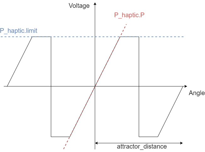
It is defined by the slope P_haptic.P and the voltage limit in the P_haptic.limit. And in the case of my code the switching in between the attraction points is done exactly in the midle of the two attractor_distance/2.
This is a very simple code though. I am sure you can do it much better ![]()
Wow, thanks for the detailed help!!!
Below is a quick video I did which explains the specific application (lathe contoller). I’ll work on incorporating your feedback and do a follow up sharing my code. This was inspired by a project I saw on hackaday called “turn by wire” Turn-by-Wire

an interesting application doable with simpleFOC

For anyone following along: Here is a 4 position virtual toggle. There is a “click” feel when you move from center to the right or left 30 degrees. Moving to the right 60 degrees you feel a 2nd click and the torque increases.
First thing was to define 3 PIDController instances
// attractor angle variable
float attract_angle = 0;
// distance between attraction points
int distance_degrees = 30;
float attractor_distance = distance_degrees * _PI / 180.0;
// track the current "detent"
int detent_num = 0;

// controllers
PIDController strongPID{.P=40,.I=0,.D=0,.output_ramp=100000,.limit=12};
PIDController midPID{.P=10,.I=0,.D=0,.output_ramp=100000,.limit=6};
PIDController weakPID{.P=10,.I=0,.D=0,.output_ramp=100000,.limit=4};
...
Then in the loop you can do away with the findAttractor, it always will pull to 0 degrees.
void loop() {
  motor.loopFOC();

  // Motion control function
  float pid_input = 0;
  switch(abs(detent_num)){
     case 0:
      pid_input = weakPID(attract_angle - motor.shaft_angle);
      break;
     case 1:
      pid_input = midPID(attract_angle - motor.shaft_angle);
      break;
     case 2:
      pid_input = strongPID(attract_angle - motor.shaft_angle);
      break;
  }
  motor.move(pid_input);
  if(motor.shaft_angle >= 2*attractor_distance){
    detent_num = 2;
  }else if(motor.shaft_angle >= attractor_distance){
    detent_num = 1;
  }else if(motor.shaft_angle <= -attractor_distance){
    detent_num = -1;
  }else {
    detent_num = 0;
  }

}
pretty cool! I’m going to hook up a stepper to see if allows for a bigger torque range and better feel.
Hello, thank you for this interesting topic! This is exactly what I’m trying to do. An indexing knob with various ratchet numbers. As a beginner, I built a prototype with a small BLDC gimbal motor, an SPI position sensor and the famous simpleFoc board and libraries (what an impressive work!). I can feel the different ratchets, but my main problem is the instability on each detent of my motor. To stabilize it, the only solution I’ve found is to add friction on the shaft. Even with low proportional coefficient, the motor seems to “over-react”. Do you have any good idea to help me to have a more stable system? Thank you.
Hey @jeanda25,
You could play a bit with the derivative coefficient, it should in theory be similar to the viscose friction. (proportional) to the velocity of the movement.
It is can easily become unstable though. So you might need to filter the position a bit ![]()
Hi @Antun_Skuric
Also, @Valentine and @runger, do you have an idea why this is not working for me?
I am trying to implement the code you wrote in to my own: GM3506, with AS5048A(via PWM)
But it just vibrate crazy back and fouth. Can you see what I might have done wrong in my implementation?
Thanks ![]()
BR, Jesper
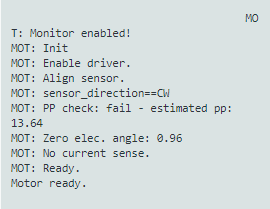
This is output from the terminal:
The code looks like this:
#include <SimpleFOC.h>

const int phU_h = 5;
const int phU_l = 6;
const int phV_h = 9;
const int phV_l = 10;
const int phW_h = 3;
const int phW_l = 11;

const int encoder_J = A3;

// BLDC motor & driver instance
BLDCMotor motor = BLDCMotor(11);
BLDCDriver6PWM driver = BLDCDriver6PWM(phU_h,phU_l, phV_h,phV_l, phW_h,phW_l);

// encoder instance - AS5048A
MagneticSensorPWM sensor = MagneticSensorPWM(encoder_J, 4, 904);

// Interrupt routine intialisation
// channel A and B callbacks
//void doA(){encoder.handleA();}
//void doB(){encoder.handleB();}

void setup() {

  pinMode(phU_h, OUTPUT);
  pinMode(phU_l, OUTPUT);
  pinMode(phV_h, OUTPUT);
  pinMode(phV_l, OUTPUT);
  pinMode(phW_h, OUTPUT);
  pinMode(phW_l, OUTPUT);
  pinMode(encoder_J, INPUT);

  // initialize encoder sensor hardware
  sensor.init();
//  encoder.enableInterrupts(doA, doB);
  // link the motor to the sensor
  motor.linkSensor(&sensor);

  // driver config
  // power supply voltage [V]
  driver.voltage_power_supply = 10;
  driver.init();
  // link driver
  motor.linkDriver(&driver);

  // set motion control loop to be used
  motor.torque_controller = TorqueControlType::voltage;
  // set motion control loop to be used
  motor.controller = MotionControlType::torque;

  // use monitoring with serial
  Serial.begin(9600);
  // comment out if not needed
  motor.useMonitoring(Serial);

  // initialize motor
  motor.init();
  // align sensor and start FOC
  motor.initFOC();

  Serial.println("Motor ready.");
  _delay(1000);
}

// haptic attraction controller - only Proportional
PIDController P_haptic{.P=10,.I=0,.D=0,.output_ramp=100000,.limit=12};
// attractor angle variable
float attract_angle = 0;
// distance between attraction points
float attractor_distance = 30*_PI/180.0; // dimp each 45 degrees

float findAttractor(float current_angle){
  return round(current_angle/attractor_distance)*attractor_distance;
}

void loop() {

  // main FOC algorithm function
  motor.loopFOC();

  // Motion control function
  motor.move(P_haptic(attract_angle - motor.shaft_angle));

  // calculate the attractor
  attract_angle = findAttractor(motor.shaft_angle);
}
At first sight your code looks correct however you do get your PP check failed.
Im unsure if your period time 904 is correct for as5048, you can check in as4058 datasheet on page 27 or 28 the proper duty cycle or you can use
examples/sensor_test/magentic_sensor_pwm_example/find_raw_min_max
To find min and max for your sensor.
Also why do you use pwm and not spi for instance?
For haptic textures SPI is pretty precise and that would be my recommendation.
Couple other questions:
Which driver IC are you using? I see you utilize 6pwm logic and I’m curious.
Also for your PID settings I would set it up as follows
P4, D0.4 I0, ramp 10000 and limit at 5
Hey @JesperSondergaard,
A few points:
- do you have to use the PWM mode of the sensor? It is very slow (1kHz) and it will make it hard to get good control of the motor. If you can switch to SPI, you’ll have a much easier time…
- although you aren’t using Serial in the main loop at the moment, I see you have it set to 9600 - bump it up to 115200 or more, for the future when you do use it in the main loop - same reason, you need to keep that main loop fast!
- I see you tune the haptic PID, but not the velocity PID - I think you need to tune it, esp. with the PWM sensor. Also the velocity LPF params will need attention.
- Which MCU are you using? Often it makes sense to run the move() loop somewhat slower than the loopFOC() - use
motor.motion_downsample = 4;to achieve a 4x downsample on the move() function, for example. - Does it work if you get rid of the haptic controller for first tests, and just set a constant velocity / torque?
Thank you for you so much for your reply. I will try the SPI and the fine tuning of the PID out tomorrow and let you know how it goes. I have tried the examples/sensor_test/magentic_sensor_pwm_example/find_raw_min_max but it did not really work for me. I’ll give it one more try.
So, heres the datasheet, would I then have to write:
MagneticSensorPWM sensor = MagneticSensorPWM(encoder_J, 4, 4119);

I am running it on an Arduino ![]()
And the driver is the TMC6300 ![]()
Hi @runger
Thanks for message, Ill try the SPI and the 115200 tomorrow and let you know how it went ![]()
If I switch to SPI, 115200 would it then be nessasary to do the downsamling?
I’m running it on an UNO at the moment, thinking to switch it ti the Micro, because of the small size, when I get it to work ![]()
BR, Jesper
TMC 6300 is my favourite low power choice.
My suggestion is to run it on 5V instead of 10V.
I know it is designed to run off max 11V but it will produce a lot of heat.
For haptic textures purposes 5V supply limit and 4V driver limit should be more then enough. Strenght of texture you can then control with PID.
(Also In Torque PID you want keep limit at 4 - torque PID can be tricky and depending on your setup it can spike current quite high. Worth to setup current limit on your bench PSU)
Also don’t forget feed your TMC with 3.3V apart from main supply voltage.
Also you don’t want to run it on more than 600mA on 5V VS.
Regarding changing baudrate, no downsampling is not necessary.
I would recommend using a faster MCU if you can - it will work with the UNO, but you’ll be quite limited both in terms of RAM and performance.
Looking at the code, I think it should be
MagneticSensorPWM sensor = MagneticSensorPWM(encoder_J, 16, 4111);
but also looking at the code, it does not look like the minimum value is used correctly - I think it needs a bug fix before it will work with this sensor.
Hi @runger Okay, cool. I also have a Nano, would that be better? Would the UNO also have difficulties with the SPI solution?
Thanks @runger. Where du you get the 16 and 4111 from? ![]()
UNO shouldn’t have problems with SPI.
And like already have been said, SPI is way to go.
I had no success with PWM for my haptic texturing project, it’s just too slow and unstable.
Depends which Nano… if you mean the original one, then no, the Nano and the UNO are both atmega 328P, just different sizes.
STM32 MCUs have many advantages for motor control, and the F4 or G4 series are very fast.
ESP32 MCUs are super-fast, and fairly easy to use. They’re well supported, and would be a good choice if you’re not planning to do current sensing.
Other than this, the other Arduinos, like the Nano IoT, Nano BLE, Nano Sense, or the MKR 1000 or MKR1010 WiFi are all supported, and while not as fast as a STM32 F4 or ESP32 they’re still a lot faster than an UNO or original Nano.
Pretty much all the Adafruit Feather boards are supported.
If you’re looking to save money, a “BlackPill” board is a cheap STM32F4 board in a small form-factor, and the ESP32 boards are generally very inexpensive.
The difference between all of these above mentioned boards and the atmega based ones like the original arduinos is that these MCUs are all 32bit, while the atmegas are 8 bit, and have more limited resources.
If you have a specific board in mind just post here and we can let you know if its compatible.
The PWM signal of the sensor has the first 12 clocks on (high), always. The next 4 clocks are used to indicate error conditions, and the following 4095 clocks encode the angle. Then follow 8 clocks which are always off (low), for a total of 4119 clocks in a PWM cycle.
The parameters to SensorPWM are the minimum pulse value (16 = 12 on + 4 error) and the maximum pulse value (4111 = 16 + 4095).
But like I said, the code is buggy. We can try to fix it up, but honestly, its not worth it. Even if the pulse measurement were perfectly accurate (which its not), the sensor operates at 1kHz PWM frequency, meaning you get at most one new reading each 1 millisecond. And since the pulseIn() function used is synchronous (e.g. it waits for a result) it means your loop speed will be even slower than 1kHz, especially on an Arduino UNO, which is slow to begin with. Add to this that you have to have fairly high filter values to further smooth the bad PWM sensor signal, and you’re in a situation where you don’t really have control of the motor…
Switching to SPI will at least make it possible to control the motor from an UNO, but don’t expect amazing performance or RPM speeds…