When I saw that, I thought of laser cutting a stencil. Maybe some brown oven/pizza paper is just what you need?
Such a thin material would need a quick laser, I’d try it in engraving mode first.
I don’t think either 3D printing or milling will lead to useable stencils. If you really want to roll your own, I’d laser them out of plastic sheets.
But since JLC will send you the stencil along with the PCBs for $8, it is kind of not worth it to make your own…
$8 plus $17 shipping ![]() Otherwise I would have done it. But yes, laser is the proper tool. I’m just not too enthusiastic about all the work to learn what kind I need and how to use it and getting it mounted on the CNC and possibly shooting my eye out or burning something else a reflected beam.
Otherwise I would have done it. But yes, laser is the proper tool. I’m just not too enthusiastic about all the work to learn what kind I need and how to use it and getting it mounted on the CNC and possibly shooting my eye out or burning something else a reflected beam.
Winter has finally come to an end, so this project can resume.
Back in January I tried plucking the components off a GooserCS using my usual stovetop heating method, but was unsuccessful. I did get them all off, but once again burnt the corners of the board, and struggled for so long that I’m not confident they’d still be functional. I should have given up at the first sign of trouble, but alas I was too impatient.
I ordered a hot air blower for more controlled heating, which set me back $40 and two weeks of shipping time. Then my whole family caught covid, me coming down with it on the day the blower arrived. Frustrating! Even after recovering my energy another week later, there was the dilemma of not being able to smell properly, so I wouldn’t know if the board was burning or not. And the outdoor air was too cold to vent if it did burn, so I had to leave it alone.
Now that I can smell most things again, and vent if necessary, I’ve been practicing with the blower. It works very well, although it is of course slower than a hot plate or oven for assembling since you have to concentrate on each component one by one to melt them. But for plucking components off of a board, heating one at a time is an advantage so the others don’t get overcooked in the time it takes to grab them all.
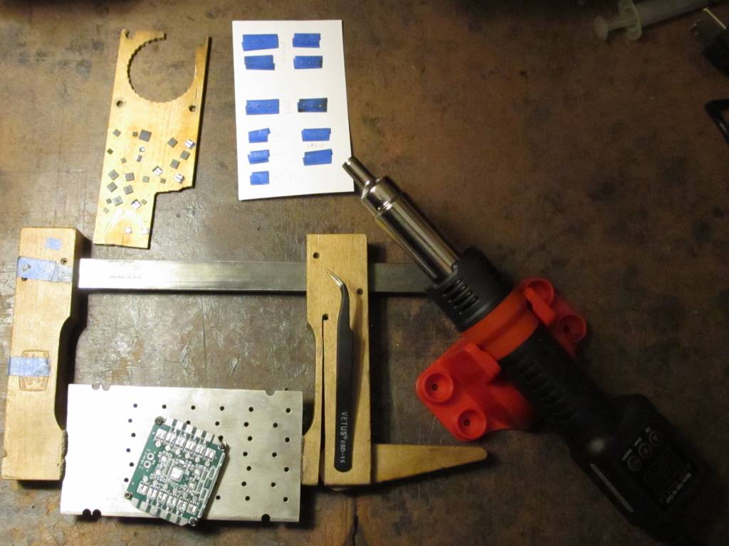
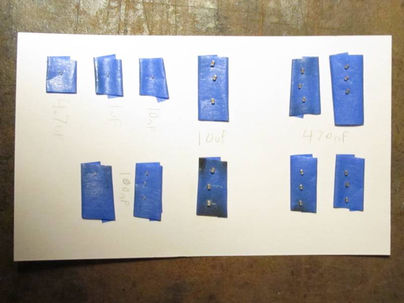
I’ve disassembled another GooserCS, this time much more successfully. No burning that I can detect, plus my practice paid off with a good method to deal with the tiny capacitors which stick to the tweezers. I put pieces of rolled masking tape on a note card to stick the capacitors on, with the capacitance values written next to them.
Here is the setup. Board screwed to a piece of aluminum with a bunch of holes in it (a pallet for milling gears for a different project) on standoffs so it’s only touching at the corners (which don’t have copper, so shouldn’t lose much heat into the aluminum). Then hold the aluminum with a cam clamp to give it more mass so it doesn’t scoot around. Wood scrap to set larger components on, paper with tape for capacitors. Preheat the whole board for 2 minutes, moving in circles from 2-3 inches above. Then concentrate on components one at a time, and after each one detaches, move the blower to its destination location on the wood or tape and heat that for a few seconds to give it a warm landing spot for less thermal shock. The tape charred a bit, but did very well at holding the capacitors.
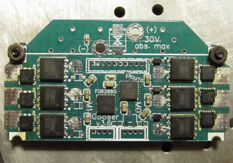
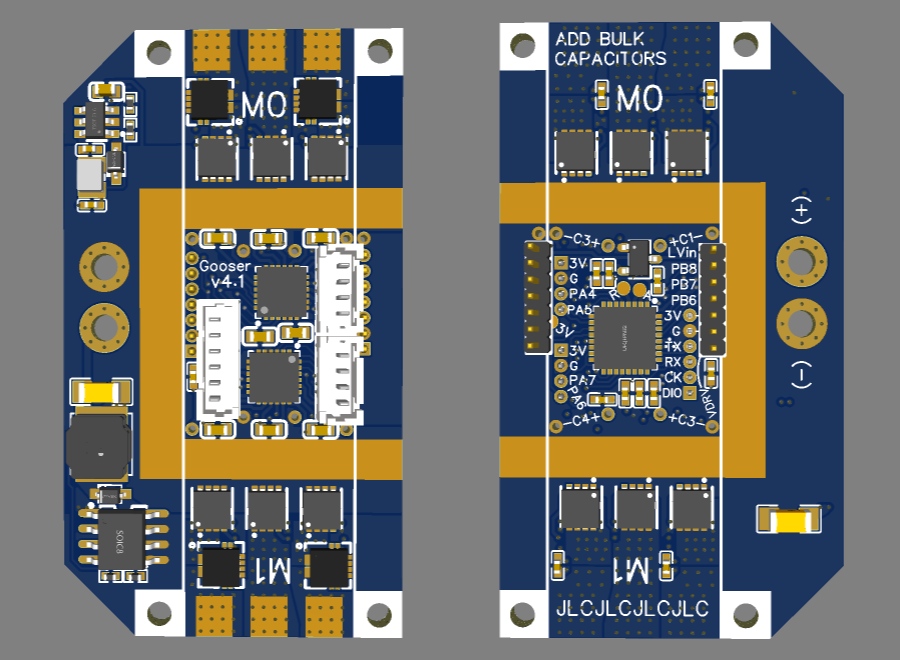
Tomorrow I’ll assemble the dual-motor board, with one DRV8300 and one FD6288Q.
1 Like
SMD assembly complete! I did the larger components by melting solder onto the pads first and then sticking them down with flux and re-melting. Capacitors were done by dotting solder paste onto their pads with a toothpick and sticking them down. The hot air blower worked great, not as much time as I expected to get everything melted. I think I can do the whole batch this way. Though I do need to buy some new solder paste and/or liquid flux. My paste is over a year past its expiration date so I was mixing in alcohol to thin it out, but it dries back out very quickly. Some people on youtube used liquid flux to liven it back up, and I could use some new flux anyway since my 20 year old rosin paste is rather dry too. It also doesn’t seem to clean off completely using alcohol and a toothpick. There’s still a bit of gummy gunk around the CPU and drivers, and yellow staining around the current sensors.
Tomorrow I’ll add capacitors and connectors and see if it works.
I like the thermally stable chipquick paste as I don’t want to run an extra fridge just for solder paste… despite being thermally stable it does tend to dry out before i can finish using it.
So when it is a bit dry, I mix in liquid flux and this makes it good as new. It doesn’t take too much of the flux, so you can add it a few drops at a time, mix well, see if you like the consistency and add some more if not.
1 Like
I just keep it in with the food. It’s 4 layers of plastic away from contaminating anything, so should be safe enough. Paste in a syringe, syringe in a ziploc bag, that inside another ziploc bag with my hot hide glue for woodworking, and then each food item has its own packaging.
Glad to hear the flux works well. The local Micro Center has it for $8, so I’ll buy that next time I’m in the area.
I’ve finally got some results from testing, and it’s another failure. Bootstraps are not working on DRV8300 or FD6288Q, giving tiny blips during deadtime just like on GooserCS.
After a fair amount of struggle with simple problems:
- This CPU programmed fine the first time, but for some reason now requires hardware reset
- Passing timer pins to the BLDCDriver6PWM constructor in the wrong order
- Silkscreen error leading me to pass a wrong pin as well
- Not knowing I needed to call setPhaseState before it would give PWM output
The CPU was finally giving PWM output. First test, the DRV8300 was “working” as well as it ever has, but the FD6288Q did not give PWM output.
Upon investigation it seems to have had a solder short. Two neighboring pins VS0B and VB0C (the naming scheme I used is pin-motor-phase, so VS0B is voltage sense pin, motor 0, phase B, and VB0C is bootstrap, motor 0, phase C) had near-zero resistance between them, and the next two pairs of neighbors had <100 ohms, even though one pair is around the corner of the chip from eachother so unlikely to solder short. I would chalk it up to internal damage due to powering it on with VS0B and VB0C shorted, except that I ultimately replaced the DRV8300 with another FD6288Q and it has a similar low resistance between VS1A and GH1A (also around the corner from eachother, but a different corner), which I’m fairly sure was not there until after I powered it on, and it never had any shorted neighboring pins to cause internal damage.
So now both drivers have two channels with the usual behavior, and one not working right. All channels are set to about 27% duty (2V out of 7.4V battery). These are the normal waveforms measured on the mosfet gate pins:
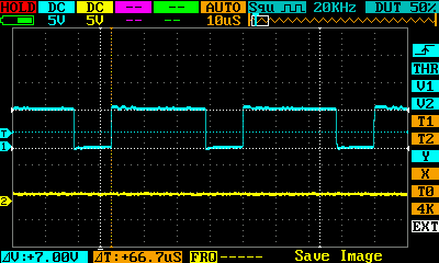
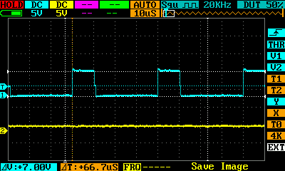
And this is the usual output (tiny blips):

The bad M0 phase C outputs a constant ~5V on the high side, and this funky ramping pattern on the low side:
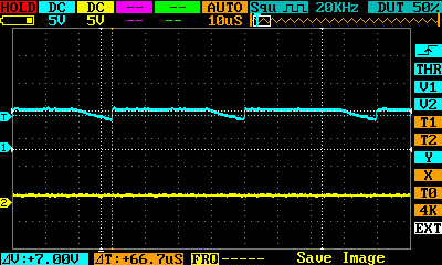
It’s mostly at 7V (usual on voltage) and starts gradually dropping when it should turn off, but only makes it down to around 5.5V before it’s time to turn back on.
The bad M1 phase A outputs a good waveform on the low side, but this funky ramping pattern on the high side:
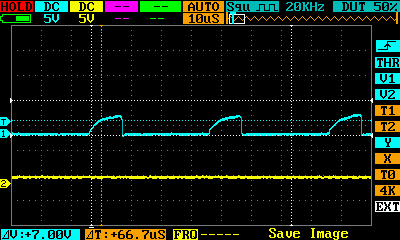
It’s mostly at 0V, but when it should turn on it ramps up with an exponential curve, getting to about 3.8V before it’s time to turn back off. Almost a perfect inverse of the other driver. Phase A instead of C, high side instead of low side, and ramping up instead of down. The only deviation is that the low side works normally whereas the other driver’s high side is stuck at 5V.
I don’t think this is particularly meaningful, but instead of tiny blips above 0V like usual, the M1 phase A mosfet output follows the same ramping pattern as its high side input. Same voltage, ramping from 0 to about 3.8V. Obviously If it was working properly, the input would be PWMing between 7.4V and 14.8V with the bootstrap boost, but it’s still interesting that it’s able to turn on with low gate voltage if it ramps up rather than switching quickly.
I’m beginning to lose confidence that I’ll ever get this working. The real mystery at this point is why does Lepton work? It’s practically identical, just with a slower CPU and no current sensors.
While debating what to do about the driver issue, I decided to test if the current sensors are working, and the answer is yes. However they seem to be very noisy. The readings on B-G431B-ESC1 vary by about 6 units out of the 4096 range at idle, whereas mine is almost twice that much. 176mA variation with the 31A sensors. And I’m using 8x oversampling, whereas ESC1 just samples it once, so mine should be better. Plus I’m only powering the 3.3V rail right now (from the STLink), so the drivers and especially motors will probably make it even worse. Perhaps instead of oversampling, I should run the sequence multiple times and filter the data for spikes before averaging the remaining values?
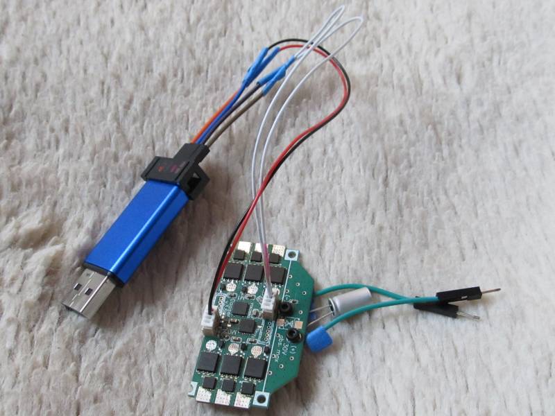
I’ve also still been struggling with getting it to connect for programming. I think I was wrong before about it ever needing hardware reset. Software reset works now, on the rare occasion that it works at all (usually I get “No STM32 device found” or “Cannot connect to access port 0…” or “DEV_TARGET_CMD_ERR”). It seems like a faulty connection to the SWDIO/SWCLK pins, so I resoldered all my wires (and replaced the bottom-dollar dupont wires I used before, which were copper plated aluminum that could only be soldered once if you’re lucky), but apparently that’s not it.
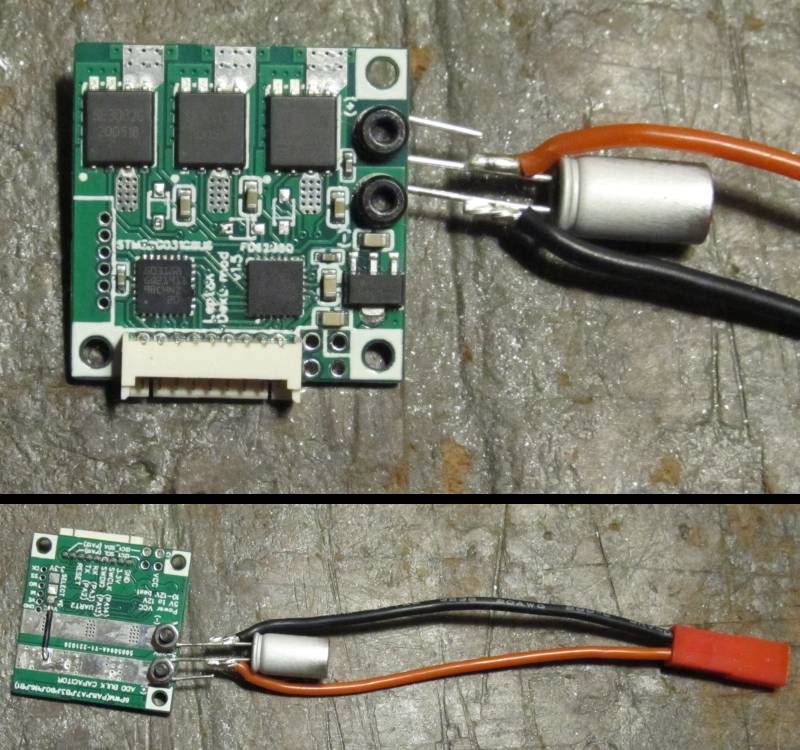
Here’s a photo of the current setup. I don’t have the proper 10-pin connectors, so I used two 4-pins for now. One to access the SWD and UART pins, and one of the encoder connectors which I’m using to supply 3V power. I’ll replace the tape on the wires with heatshrink later, once I’m sure those joints are not the problem. And of course those two green wires and capacitor screwed to the high voltage inputs are temporary, and a disaster waiting to happen if I plug the battery in backward ![]()
Here is the ADC code, incase it’s ever of use to anyone:
RCC->AHB1ENR |= RCC_AHB1ENR_DMAMUX1EN | RCC_AHB1ENR_DMA1EN;
RCC->AHB2ENR |= RCC_AHB2ENR_ADC12EN;
RCC->CCIPR |= RCC_CCIPR_ADC12SEL_1; // ADC use SYSCLK
// Dual mode regular simultaneous, circular DMA, DMA enable for 12-bit, clock 170MHz/4 = 42.5MHz
ADC12_COMMON->CCR = 6 | ADC_CCR_DMACFG | ADC_CCR_MDMA_1 | ADC_CCR_PRESC_1;
ADC1->CR &= ~ADC_CR_DEEPPWD; ADC2->CR &= ~ADC_CR_DEEPPWD;
ADC1->CR |= ADC_CR_ADVREGEN; ADC2->CR |= ADC_CR_ADVREGEN;
delayMicroseconds(20); // Regulator startup time from STM32G431CB datasheet
ADC1->CR |= ADC_CR_ADEN; ADC2->CR |= ADC_CR_ADEN;
while(!(ADC1->ISR & ADC_ISR_ADRDY)){} // Wait for ADC startup
ADC1->CFGR = ADC_CFGR_DISCEN | ADC_CFGR_DISCNUM_2 | ADC_CFGR_DISCNUM_0; // 6 values per ADSTART
ADC1->CFGR2 = ADC_CFGR2_ROVSE | ADC_CFGR2_OVSR_1; // 8x oversample, giving 0-32768 range
ADC2->CFGR2 = ADC_CFGR2_ROVSE | ADC_CFGR2_OVSR_1;
#define ADCSQ(idx, ch) ((ch) << ((idx)*6)) // More concise than the ADC_SQRx_SQy #defines
// Note: Actual number of conversions is 1 more than specified in SQR1 low bits.
// Note: ADC1 and ADC2 can't convert the same channel number at the same time.
// With this configuration, each ADSTART converts one motor's current sensors and hall
// sensors simultaneously, plus one of the extra solder pads on the back of the board.
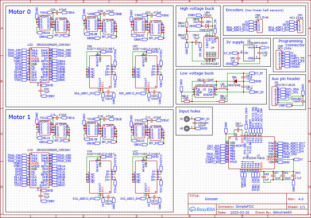
ADC1->SQR1 = 5 | ADCSQ(1,2) | ADCSQ(2,10) | ADCSQ(3,1) | ADCSQ(4,11); // M0SA, M0SC, M0SB, M1HA
ADC1->SQR2 = ADCSQ(0,14) | ADCSQ(1,3); // M1HB, PA2
ADC2->SQR1 = 5 | ADCSQ(1,5) | ADCSQ(2,4) | ADCSQ(3,10) | ADCSQ(4,17); // M0HA, M0HB, PF1, M1SA
ADC2->SQR2 = ADCSQ(0,13) | ADCSQ(1,3); // M1SB, M1SC
DMAMUX1->CCR = 5; // ADC1, from Table 91 on page 420 of reference manual rm0440
DMAMUX1_RequestGenerator0->RGCR = DMAMUX_RGxCR_GE;
DMA1_Channel1->CNDTR = 6;
DMA1_Channel1->CPAR = (u32)&ADC12_COMMON->CDR;
DMA1_Channel1->CMAR = (u32)&adcData;
// 32-bit memory, 32-bit peripheral, increment memory address, circular mode
DMA1_Channel1->CCR = DMA_CCR_MSIZE_1 | DMA_CCR_PSIZE_1 | DMA_CCR_MINC | DMA_CCR_CIRC;
Then to start a conversion:
    DMA1_Channel1->CCR |= DMA_CCR_EN;
    ADC1->CR |= ADC_CR_ADSTART;
You could wait for the EOS flag in ADC1->CSR to be set when it’s finished, but in my case I’ll be starting one motor’s readings before updating the other motor, so it will be long since done by the time I need the results.
I am really not into the details of what your are doing there, and probably I misunderstood something. You wrote that only 3.3V are powered. Does that mean your Vbus is floating? I guess that would explain your noisy current readings. Since you generally know pretty well what you are doing, I just missed something here.
That is correct.
I just tried it with the battery, with PWM set to 0 duty so should be 0V output on all pads. No difference.
I also tried using the 3V power from the FTDI adapter instead of the STLink, and no difference. And from an LD33V regulator connected to the first cell of the battery balance connector, which was same or worse, hitting up to 14 units variation (over twice the ESC1).
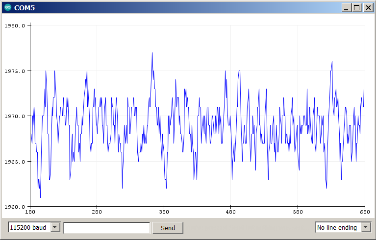
Here’s what it looks like on serial plotter. 100ms between prints, no oversampling on the ADC.
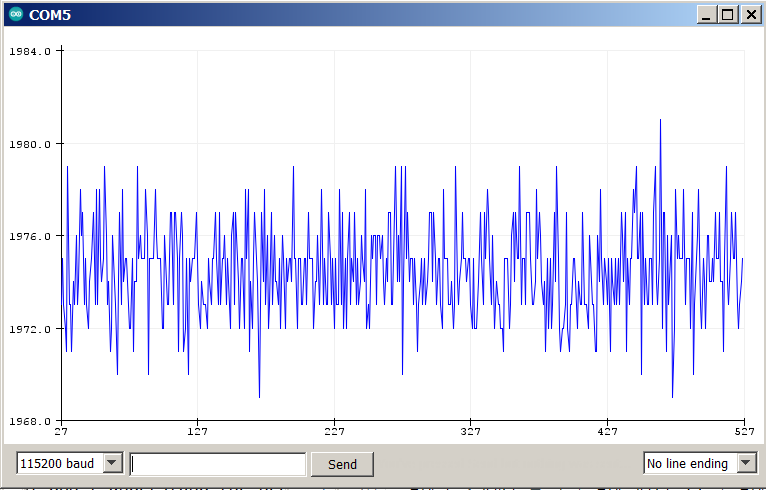
I don’t think my idea of filtering spikes would help. The data is too chaotic, plus the range of variation is about the same as with oversampling, which means that it often gets 8 consecutive readings of the extreme values.
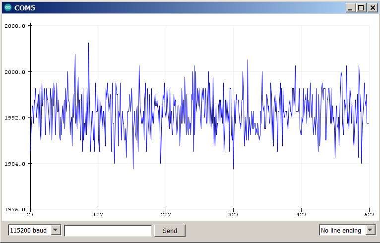
EDIT: To make sure it wasn’t anything to do with my soldering, I tried this ADC code on GooserCS which was assembled by JLCPCB. It’s even worse! Variation up to 22 units, almost four times that of ESC1. Again no difference whether the drivers and mosfets are powered or not.
EDIT2: Hmm, this may be expected for these sensors. Reading the datasheet more closely, it says voltage noise with no external lowpass filter is 8mV. That works out to about 10 ADC units. Though I do have 100nF capacitors between output and ground, which I think qualifies as a lowpass filter. And the 22 unit variation on GooserCS is definitely weird, when I designed the board to minimize interference as best I could, and there’s nothing happening to cause any regardless. But even if I can’t use them for foc_current mode, just being able to detect overcurrent and prevent burning in voltage-based current mode would be good enough for me. In that case two sensors is best to minimize cost, so hopefully I can get GooserCS going with the DRV8300.
What happens if you connect your Vbus (limited to almost no current or connected through a resistor) and measure with at least a small duty cycle? The idea is to have at least some current flowing to make sure that the current sensor inputs are not floating? Of course, you then also need to connect resistors or a small motor to the phases.
No can do since the high side mosfets won’t turn on. I had considered soldering a wire to the mosfet output pins and to the motor wire pad so I can run current across the sensor with a battery and resistor, but I don’t know if it would give meaningful information. I would get a current reading from it, but I assume whatever noise was going on before would be superimposed on it.
Reading the datasheet for the 30A sensors used on Valentine’s no-longer-available Qvadrans board, it lists the noise as 20mV, which works out to 25 ADC units. But it looks like it doesn’t use the full output range since the sensitivity is listed as 44mV/A, so 20mV works out to 455mA noise. The sensitivity on my sensors is about the same at 45mV/A, so my previous calculations underestimated the noise in amps. The listed 8mV noise is 178mA, and my GooserCS measurement works out to 394mA.
So apparently hall sensors are not very accurate. That explains why most people go to the trouble of creating those incomprehensible resistor networks, reduced PWM range, and tight ADC timing of low-side sensing.
At long last I’ve acquired a bit of useful information! Lepton does work with DRV8300 after all. It was some combination of other damage and poor soldering skills that resulted in the failures on the one I tried before.
I want to avoid ordering components from LCSC until I know for sure which direction I’m going, but I also wanted to test an FD6288Q that hadn’t been exposed to my crude stovetop reflow method. So it was with a heavy heart that I decided to pluck one off of an unused Lepton. A side benefit was getting to test one of the DRV8300’s I desoldered from GooserCS with the heat gun on a Lepton that’s never burnt a mosfet or been exposed to stovetop soldering.
Sadly after installing the good FD6288Q on Gooser3, it died immediately with a tiny wisp of smoke from the vicinity of the PWM input pins. They now show low resistance to ground, similar to the bad pins on the other two FD6288Q’s I’ve tried on this board. Odd that all three have burnt near a corner of the chip, but it’s been a different corner every time.
The Lepton, on the other hand, works perfectly. Bootstraps are boosting the high side gate voltage (using the internal diodes, since I removed the ones from the board), and mosfet outputs are showing a proper waveform. I also made a less hazardous screw-on battery cable for testing. It has a proper polarized connector, and is much easier to screw on since I don’t have to get both the wire and capacitor lead pinched under the screw.
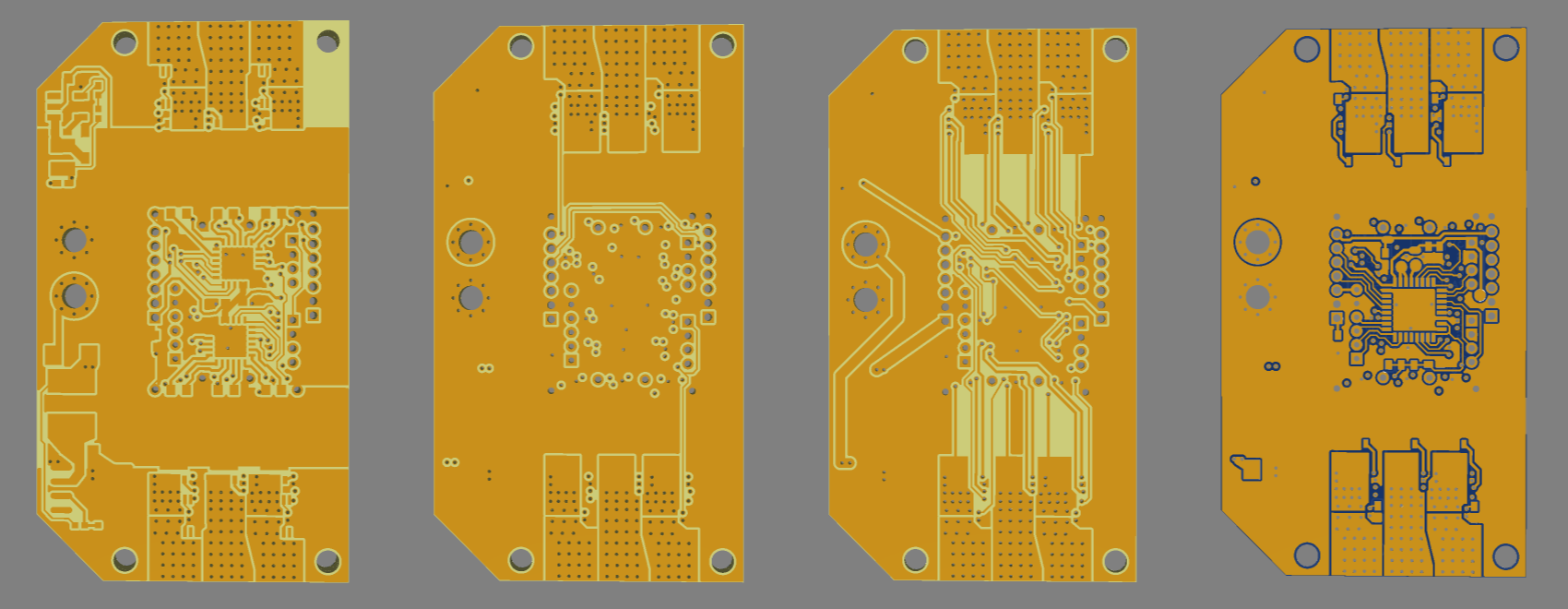
So I can reasonably conclude that there is a circuit design error in GooserCS and Gooser3. The only possible thing I can think of is that I’m running the high gate traces on the top layer underneath the bootstrap capacitors (between the capacitor solder pads), while Lepton, Qvadrans, and the DRV8300 datasheet’s layout example use vias to get around them. Gate lines shown in red, capacitors outlined in green.
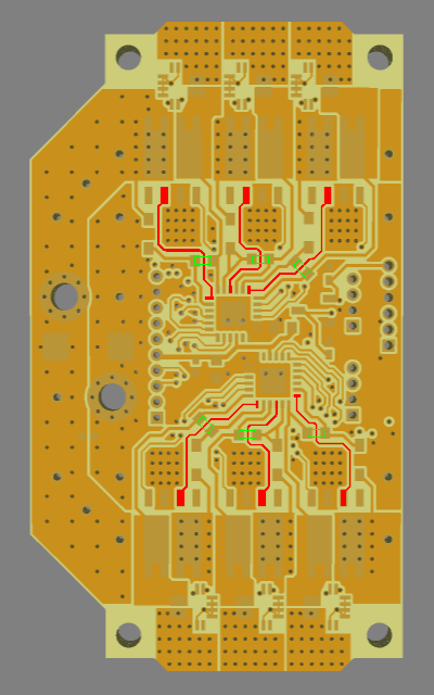
There shouldn’t be any significant inductive effects between a PCB trace and a capacitor, correct? The thickness of the soldermask over the gate trace could cause the capacitor to be very slightly off-kilter, resulting in a thicker solder layer between it and the board copper on one or both terminals, but I can’t imagine the tiny increase in resistance from that being such a consistent problem. And Lepton does have one low-side gate trace go between capacitor pads, though it is one of the 10uF power capacitors rather than a bootstrap.
Hey @dekutree64,
This is very interesting!
In the first iteration of the DriveShield I’ve started form lepton and used DRV8300 with the SE3082G (its the version v0.1). And I was not able to get them to work at all. My DRV8300 were burning right away. So I figured it’s my ignorance that is causing this and I switched to the more integrated driver DRV8320. This time the current limiting stepped in and the driver was not burned, but I was never able to get any real output from the mosfets.
Once again my ignorance is probably the issue ![]()
But just in case its not I started doubting the mosfets SE2082G. I unsoldered them and tried to trigger them by hand on a breadboard and I was not able to trigger them properly, they kept burning right away. Once when I switched to the discrete mosfets I had no more issues. (more or less the same circuit on the driver side).
So provided that its not the issue of my lack of experience (a big if :D), do you think that it might be a SE2082G batch issue?
1 Like
That would explain everything. I never considered that it might not be my fault ![]()
I remember placing my Lepton order in a hurry because the mosfets had almost run out and I didn’t know if/when they’d be restocked. So the working ones are from the previous batch. That was October 2022. They got a new reel sometime not too long after that and haven’t run out again, so your DriveShield and my Goosers are all made from the current reel.
I’ve also tried twice to repair burnt Leptons using mosfets pulled from GooserCS, and failed both times. Back in post #49 of this thread, the mosfet I got Gooser-like output from was the transplanted one.
So now what? We should probably inform LCSC about the potential problem. Maybe they have some way of testing them.
Between all my remaining Leptons, I do have enough of the old batch to complete my robot using GooserCS. But few if any spares, so it would be a major setback if I burn any of them. Then again, redesigning the board for discrete mosfets at that point would be no more work than doing so right now. If I do redesign now, then I don’t have to tear up the Leptons, but I’m not sure if I’d ever have a use for them in the future anyway.
UPDATE: Confirmed! GooserCS works fine with mosfets transplanted from Lepton. No other changes, so 100% certain the mosfets are to blame. Thank you Antun! I never would have figured it out on my own.
1 Like
Yeah me too, I was a bit confused and perry sure that it was me. Since we never had anyone have issues with leptons and other boards using them, so I figured it’s my design. ![]()
We moved recently and I do no longer have any of the old boards with these MOSFETs so I’m no loger able to test them really.
The behavior with the drv8300 was basically instant burning of the driver without even connecting the motor.
With the drv8320H, as it has much more protections it did not burn, but it would turn off due to the over current protection each time the high-side MOSFETs would turn on. (No motor connected). I’ve looked into it with a scope and I could see the gate input pwm rise and then being cut after just a couple of micros. (I’m not 100% about the exact duration).
So when I’d look at if with a scope or a multimeter it looked like the low-side MOSFETs would always be on or something similar, making the shoot through every time the high side is on.
I started doubting the soldering then, maybe my board was not as well designed as valentine’s and maybe the high-side and low-side pads were connected due to the soldering issues related to my design.
So I’ve unsoldered one of the MOSFETs from a new board and tried to trigger it’s high side stage by hand and it just blew up (burned) in my hands. ![]()
So I started to doubt everything I know about transistors and MOSFETs. So I tried to verify what I was doing with a set of other MOSFETs had laying around (I’m not even sur what they are - probably ir3025) and I had zero issues.
So my next step was to use different MOSFETs, so I went for a discrete set of high and low-side 3x3mm MOSFETs. And I had zero issues with more or less the same driver circuit.
As I said, its really unfortunate, but I’ve thrown away my boards few weeks ago and I don’t have any one of those to do more tests on. ![]()
The DRV8300’s on my GooserCS were undamaged by running with the bad mosfets, but FD6288Q on Gooser3 did burn immediately. DRV8300 on it seemed to be ok, same as GooserCS, but I haven’t tried good Lepton mosfets on it yet.
I didn’t mention this yesterday since I don’t think it’s particularly meaningful, but I did kill a DRV8300 on Gooser3 yesterday using mosfets pulled from two Leptons that had burnt while running motors in the past. Each had one visibly burnt mosfet that I threw away, but I guess the others were damaged as well, or damaged by the heat of stovetop desoldering. During yesterday’s test, one mosfet died with a snap immediately when I connected the battery, and another after 20-30 seconds of running. I think the driver died with the first one because none of the gates were receiving PWM during my short time of probing before the second one blew. Several driver pins have low resistance to ground now.
EDIT: I thought I’d found some footprint-compatible substitutes for SE3082G, but no. I forgot the reason it’s so difficult to find any is because they usually have two fully independent mosfets in one package, rather than the internally connected drain and source which gives a single pad for the motor wire.
I’ve informed LCSC of the problem with the current reel. I’ll continue with what I have on hand for now and see if they get a new reel before redesigning for single mosfets.
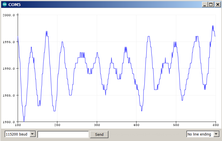
I’ve done some more investigation of the current sense noise on GooserCS, and it seems the 100nF filtering capacitor does more harm than good. It smooths everything above ~30KHz, but the amplitude of the remaining noise is about the same as it is unfiltered. Here are the data plots for unfiltered, 100nF, and 1uF. Somewhere around 360 microseconds worth of data.
The driver I soldered the good mosfets on has 15A current sensors, so that’s what I’m testing now. 90mV/A sensitivity, and 11mV noise from the datasheet, but I’m measuring around 24 ADC units (19mV, 211mA) typical variation, with occasional spikes reaching up to 72 ADC units peak to peak (58mV, 644mA).
The 1uF smooths everything above ~12KHz, and reduces the amplitude by about half, but oversampling works better. With no capacitor, I can get it down to 10 ADC units (8mV, 90mA) if I average the samples over a 10 microsecond period, and 5 ADC units over 30 microseconds. Diminishing returns beyond that.
The 100nF capacitor doubles the time it takes to get similar results by averaging, and 1uF was even worse, so for now I’ll go with 30us sampling period, unfiltered. Still probably too noisy for foc_current mode on my smallest motors that can only handle around 1.5A continuous, but probably ok for the 10A largest ones. And certainly usable for overcurrent protection in voltage-based current mode on any motor, once I figure out how to go about enforcing it.
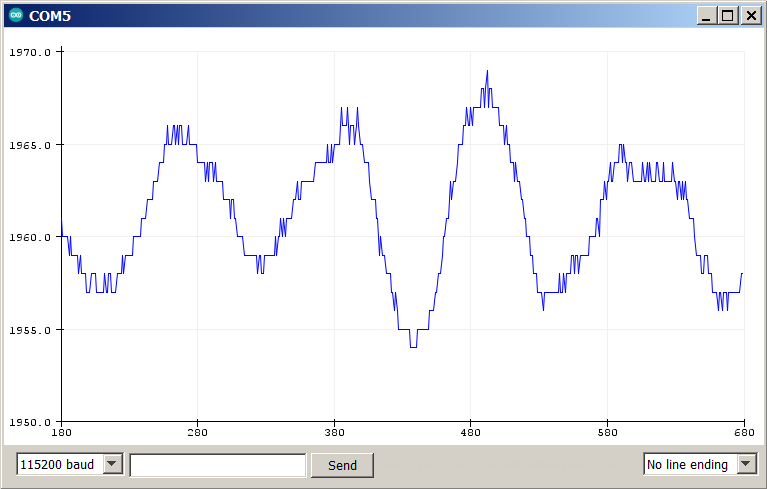
Up next: Spinning my old friend, the smallest motor. I machined a stator mount for it with linear halls back then, but never got around to testing it until now. They give good sinusoidal waveforms, and remarkably clean output. Only 3 ADC units of variation when sitting still.
1 Like
You know what’s more fun than motor testing? Designing yet another PCB!
Similar philosophy as Gooser3, being a two-motor board which can optionally be cut smaller for one motor or tiled for more, but using single mosfets instead of the SE3082G changed the optimal power rail structure. Instead of two rails on the back and mosfets on the top, I now have the 3 positive mosfets on top and 3 negative on the back. This results in the inner layers being unusable for power distribution since I can’t spam vias everywhere, but you can still solder on heavy copper bars. I also lost my place to spam 1206 capacitors for bulk capacitance. Instead there are two pairs of holes for electrolytics on each motor.
The tileable section width is 14mm. The smallest usable size is 14x32mm for a single motor, and 14x50mm for dual-motor with separate power wires to each motor’s rails. 10mm of extra width adds a power distribution area with input holes, and buck converters to step the voltage down to 12V for the drivers and 4.3V for the 3V LDO input (it can also output 5V for any projects that need it, by replacing the 47k resistor with 56k).
Unfortunately the motor wire pads take up the full 14mm basic width, so holes for mounting screws require extra width.
I’m back to 3PWM and two ACS711 current sensors like GooserCS. I had to use the 32-pin STM32G431 to fit in this small size, and it only has one complete set of 6PWM pins. And now that I know hall current sensors need an extended sampling period to reduce noise, using two of them on different ADC units allows simultaneous sampling of both rather than having to cycle through 3 of them. Plus there wasn’t enough room to get the last two ADC lines out to them without increasing the board size.
P.S. While browsing on LCSC a while back, I randomly happened upon SMT copper sheet which is inappropriately placed in the “consumables” category. Small pieces of copper and brass which can be soldered by pick-and-place machine. This enables adding heavy copper bars for increased current without having to make and solder them yourself. The selection is pretty limited though. The two best for this board are 25x1.5x1mm (C18548290) and 10x2x1mm (C18548288). The long one is good for 4+ motor boards, the short one for single or dual motor.
1 Like
Ok, I think it’s ready to order.
- Removed all non-ground routing from Inner1, except for the I2C lines which would otherwise be very difficult to get across the board.
- Extended the VS areas on Inner2 for possibly improved heat dissipation.
- Completed various non-essential ground connections that were too small for copper fill to do automatically.
- Top layer has HV_IN wrap all the way around now, with exposed copper on the right edge so you can solder electrolytic capacitors along there if you want.
- Isolated mounting screws from ground plane.
- Found some space for ceramic capacitors on the back in the input area. Exposed copper is suitable for 1206 or 0805. I placed 50V 0805 in the model since they’re available as a JLC basic part, but for 25V and 35V, 1206 has higher capacitance available.
- Found a way to utilize the inner copper for power conduction in the input area. Inner2 is filled with positive (aside from the buck output traces that pinch it somewhat), and there are positive and ground vias in the areas above/below the horizontal rails.
- Added TVS diode. The two-way SMBJ30CA from Qvadrans/Gooser3 is too big, but the one-way SMM4F26 from B-G431B-ESC1 fits. LCSC doesn’t have any in stock, but they are available from Mouser and Digikey. For some reason the positive pad is showing as a hole in the 3D model view, but it looks ok in the gerber. I’m just copying other people without entirely understanding what these things do, but I’m guessing it should be swapped for SMM4F33 if using 40V mosfets.
- Input terminals are now centered vertically. They feel a little crowded by the capacitors and buck inductor, but clearance is no less than the distance between the holes, and you can still fit an XT30 connector if desired.
And here is why I was excited about getting the tileable area down to 14mm wide. The version I’ll actually be ordering has all 8 motors on a single board instead of having to stack two 4-motor boards like my previous designs.
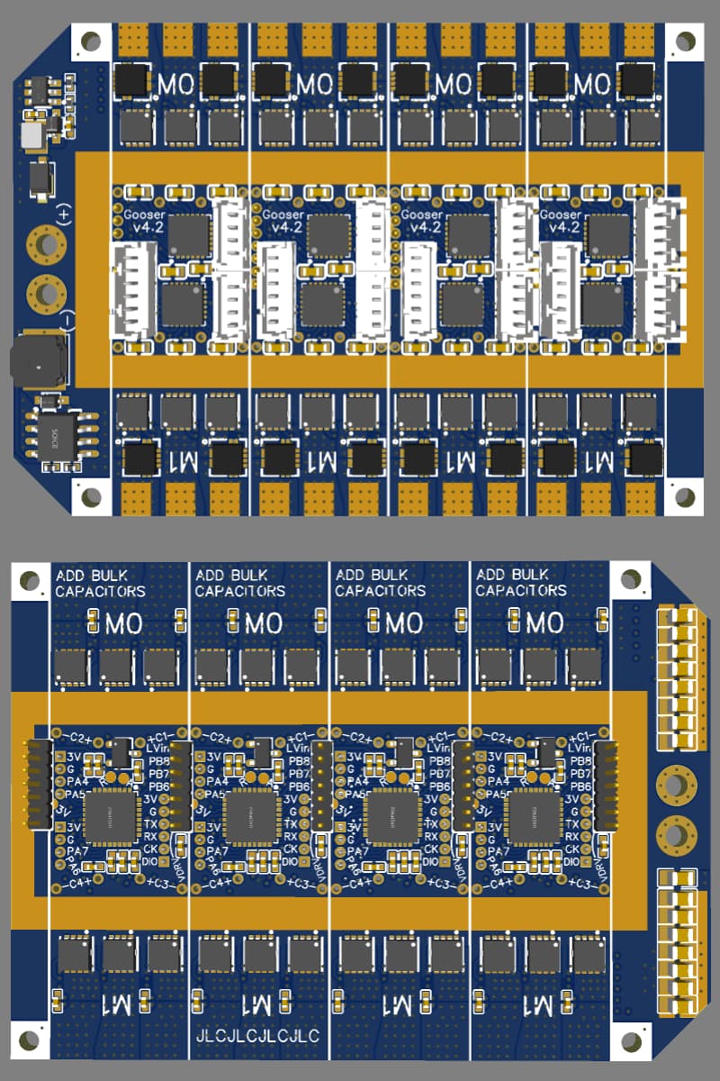
I call this version the Egg Basket, keeping with the goose theme and because I’ve put all my eggs in one basket compared to having individual motor drivers that can be replaced if they burn. But since I can desolder individual components with the heat gun, it should be repairable as long as the PCB dielectric doesn’t get too badly charred by a burning mosfet.
I’ve also completed the initial motor testing on GooserCS without incident. It spins fine in closed loop with TorqueControlType::voltage, but foc_current just makes a buzzing noise and doesn’t move. Needs more investigation.
UPDATE: Small motor is running well in foc_current now. The main problem was forgetting to multiply by adc_voltage_conv in my override of _readADCVoltageInline, so my current readings were nonsense.
Overall performance is surprisingly unchanged from my old setup with digital halls and voltage-based current limiting. Max continuous current is still 1.5A, and positioning accuracy is the same due to this motor’s strong cogging torque. The main advantages are now I only need two sensors on the motor, no filtering capacitors, and don’t have to worry quite so much about sudden burning.
On to the next one!
2 Likes