Gooser5 is finally verified fully functional!
I somehow forgot to buy the 51k resistors for the low-voltage buck feedback and vbus sense, but 1k and 4.7k gives a usable ratio for the buck (4.3V output rather than 4.6V), and I just left vbus unpopulated since I don’t need it, it’s highly unlikely to have any issues, and would waste 50mW if I use these lower value resistors.
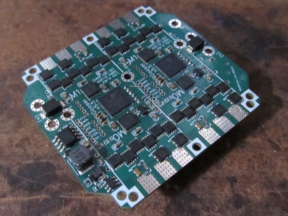
I used the low-cost JMSL0302 on one motor and even-lower-cost AGM403P on the other three. I’ll be using this on my milling machine, so the low resistance of JMSL0302 is good for the spindle, and slightly higher resistance of AGM403P is a non-issue for low-current stepper motors.
I only populated two current sensors per motor, since I wouldn’t use the third anyway. I soldered copper bits across their pads to complete the connection to the motor wire pads.
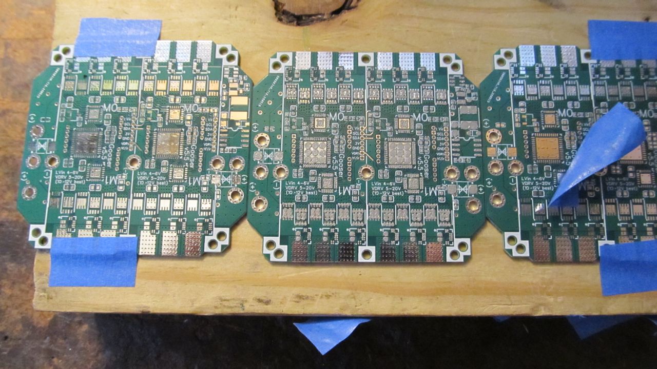
Here is the setup with my stencil made from an aluminum can with CNC drilled holes for the pads. Double stick tape under the board, two spare boards to serve as spacers, and then fiddle the top and bottom tapes until it’s as flat as possible (still a small bubble in the buck converter area).
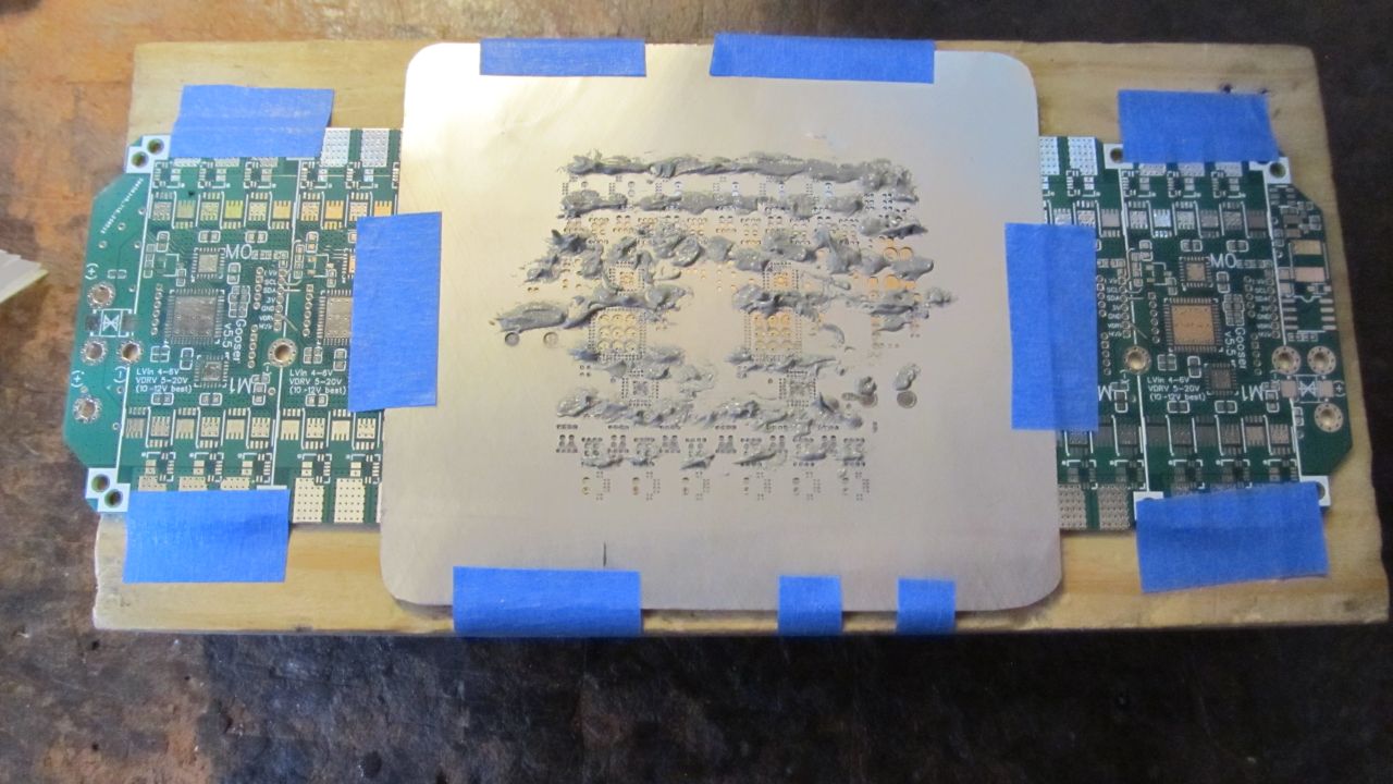
I laid the paste on thick, and took two swipes from top to bottom (my spreader isn’t wide enough to do it in one). Somehow it still didn’t fill everything. Maybe I need to gradually tilt the spreader down as I move, to be sure the paste doesn’t just stick to it and then get lifted away if I unintentionally tilt it up as I move. I held the bubble down and scrubbed at it a bit more until everything was filled. Came out clean enough that I didn’t have to do any toothpick editing.
After placing all the components, I wicked some Kester 186-18 liquid flux (one of the stickiest substances I’ve ever encountered) around them to hopefully help resist blowing away from the heat gun. It worked.
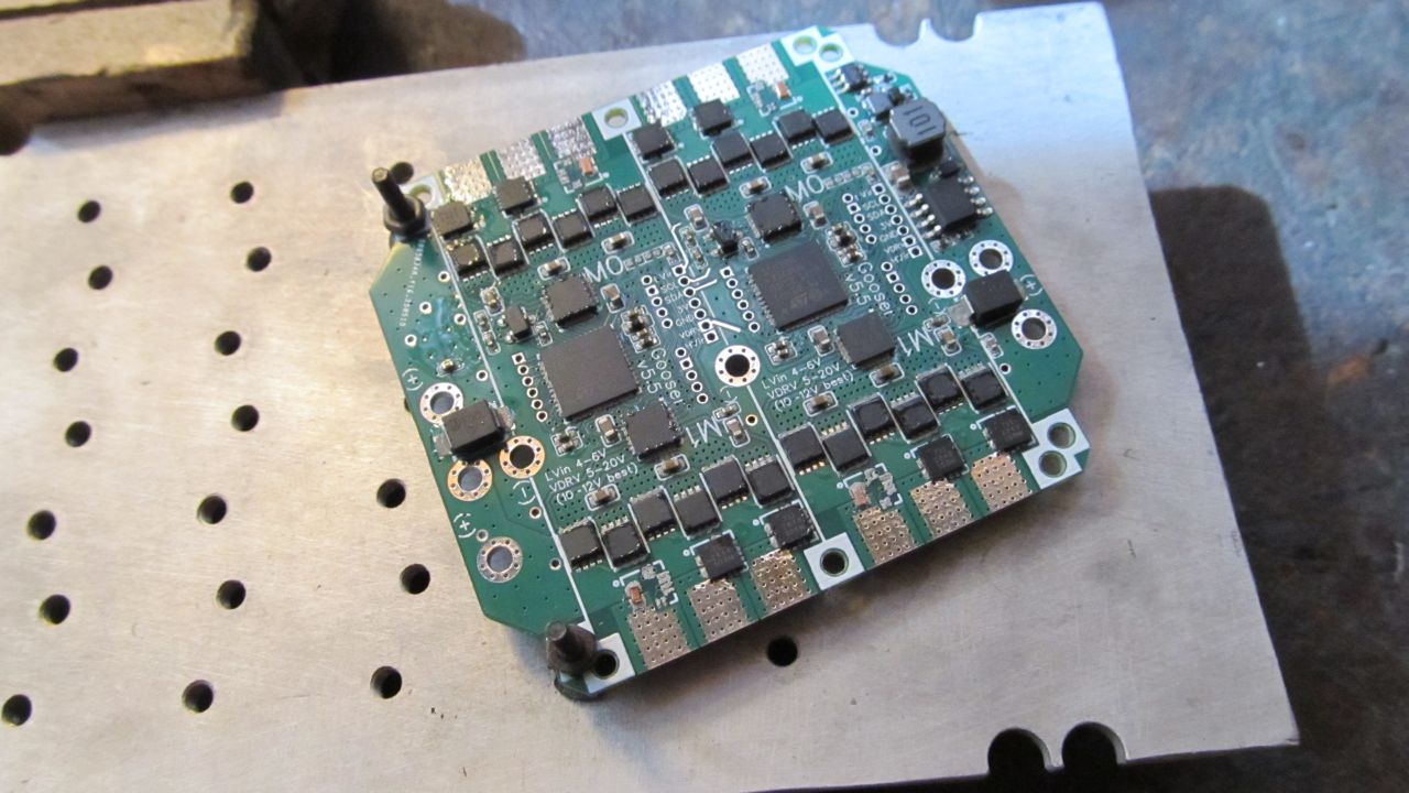
It turned out there was a bit too much solder on the 0.5mm pitch pins. I think my stencil holes are slightly too big. But they can be fixed with the soldering iron afterward.
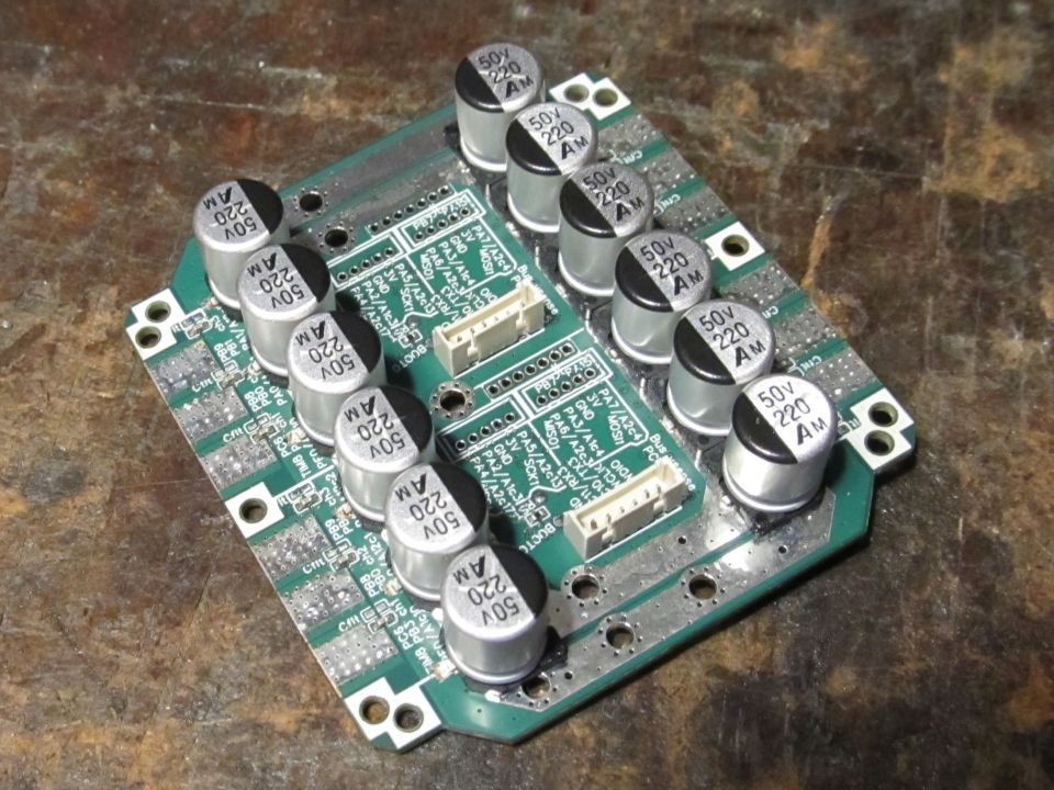
I had to scrape off some solder mask on the back to make pads for SMD electrolytic capacitors. I used three 50V 220uF per motor, which is less than Valentine’s recommended 1000uF per motor on Lepton, but still more than I see most people using. I should have bought more 35V 470uF instead. I had forgotten that electrolytics can be pushed closer to their limit than ceramic and polymer.
Soldering them was a bit of a struggle for the heat gun, and they look like they could have used some more solder, but it’ll do. I had hoped it would be possible to do them with a soldering iron so more people would be able to order single-side assembly and do the back side at home, but I think not. I didn’t actually try it, but I doubt you’d be able to get it to melt with so much heat sinking, and even if you could it would be a challenge to keep the capacitor from sliding around. Might work if you warm it up on a 3D printer heat bed to reduce the temperature difference. Even just soldering the connectors was a lot easier when I warmed it up with the heat gun first.
After some testing, it looks like the JMSL0302 mosfets (30V, 1.2mOhm) can handle 10 amps continuous without cooling, and AGM403P (40V, 2.7mOhm) can handle 8 amps. This is using the getDCCurrent function (the individual phase currents are a bit lower), and my finger as a temperature probe. So heavy copper bars are highly effective, since I got 15 amps when I tested with them before. I was planning to remove the large soldermask openings in the next version, but it might be worth trying stacked copper bars and SMD electrolytics after all.
EDIT: Copper bars do nothing! Apparently BSZ0901 mosfets are much better than JMSL0302, despite similar datasheet values.
I was annoyed at the idea of losing 1/3 of my usable spindle torque, so I desoldered 3 of the capacitors, scraped some more solder mask, added some copper bars (about 1x3mm) and soldered the capacitors back on top of them. 10 amps remains the limit before it gets uncomfortably hot to touch.