My current project of closing the loop on my CNC stepper motors is going to need non-blocking I2C communication, but I’ll probably just go with direct hardware register access. ATMega’s TWI registers are easy to work with. I haven’t learned STM32’s yet, but since that library wouldn’t work with it, I’d have to go looking for a different one anyway.
My plan is to have one Nano that runs GRBL, whose job is to process the data stream from the PC and output step/dir signals to the motor drivers (my Gooser5), and an Arduino Pro Mini whose job is to read some of the manual controls and send I2C commands to the drivers, and receive the motor positions from the drivers to display on a little OLED. The drivers will run in angle_nocascade mode since GRBL already handles generating acceleration ramps for them.
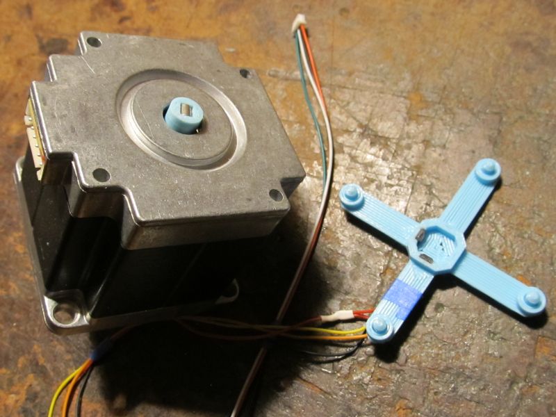
I’ve been working on some fun encoder code, using two 49E linear hall sensors and a 3x4mm cylindrical magnet on the motor shaft.
Near-micrometer resolution on SFU1204 ball screws with less than $1 in hardware thanks to STM32’s awesome ADC
#ifndef SIN_COS_ENCODER_H
#define SIN_COS_ENCODER_H

// This function can be overridden with custom ADC code on platforms with poor analogRead performance.
__attribute__((weak)) void ReadSinCosEncoder(int pinA, int pinB, uint16_t *a, uint16_t *b)
{
  *a = analogRead(pinA);
  *b = analogRead(pinB);
}

class SinCosEncoder: public Sensor {
  public:
    SinCosEncoder(int _pinA, int _pinB) : pinA(_pinA), pinB(_pinB) {}

    void init(uint16_t _minA, uint16_t _maxA, uint16_t _minB, uint16_t _maxB,
      uint16_t _centerA, uint16_t _centerB, uint16_t _thirtyA, uint16_t _sixtyA, int _lut_resolution,
      const uint16_t *_lutAP, const uint16_t *_lutAN, const uint16_t *_lutBP, const uint16_t *_lutBN)
    {
      minA = _minA; maxA = _maxA; minB = _minB; maxB = _maxB;
      centerA = _centerA; centerB = _centerB; thirtyA = _thirtyA; sixtyA = _sixtyA;
      lut_resolution = _lut_resolution;
      lutAP = _lutAP; lutAN = _lutAN; lutBP = _lutBP; lutBN = _lutBN;
    }

    // Perform full calibration. The tables passed in here will be filled with data and their pointers retained.
    void init(FOCMotor *motor, int calibration_steps, int _lut_resolution,
      uint16_t *_lutAP, uint16_t *_lutAN, uint16_t *_lutBP, uint16_t *_lutBN)
    {
      int i, j;
      uint16_t a, b;
      int32_t tableA[calibration_steps+1]={0}, tableB[calibration_steps+1]={0}; // Extra entry at the end to simplify interpolation code

      lut_resolution = _lut_resolution; lutAP = _lutAP; lutAN = _lutAN; lutBP = _lutBP; lutBN = _lutBN;

      Serial.println("SinCosEncoder: Begin calibration movement");
      // Rotate motor forward and back, recording the sensor values at each step.

      // Move slightly negative, so first loop iteration moves forward like subsequent iterations
      motor->setPhaseVoltage(motor->voltage_sensor_align, 0, _electricalAngle(-1 * _2PI / calibration_steps, motor->pole_pairs));
      delay(2000 / calibration_steps);
      for (j = 0; j < 4; j++)
        for (i = 0; i < calibration_steps; i++) {
          uint32_t time = 2000000 / calibration_steps, start_time = _micros();
          while(_micros() < start_time + time) {
            float a = (i - 1) + (float)(_micros() - start_time) / time;
            motor->setPhaseVoltage(motor->voltage_sensor_align, 0, _electricalAngle(a * _2PI / calibration_steps, motor->pole_pairs));
          }
          ReadSinCosEncoder(pinA, pinB, &a, &b);
          tableA[i] += a;
          tableB[i] += b;
        }
      // Complete previous revolution, so first loop iteration moves backward like subsequent iterations
      motor->setPhaseVoltage(motor->voltage_sensor_align, 0, 0);
      delay(2000 / calibration_steps);
      for (j = 0; j < 4; j++)
        for (i = calibration_steps - 1; i >= 0; i--) {
          uint32_t time = 2000000 / calibration_steps, start_time = _micros();
          while(_micros() < start_time + time) {
            float a = (i + 1) - (float)(_micros() - start_time) / time;
            motor->setPhaseVoltage(motor->voltage_sensor_align, 0, _electricalAngle(a * _2PI / calibration_steps, motor->pole_pairs));
          }
          ReadSinCosEncoder(pinA, pinB, &a, &b);
          tableA[i] += a;
          tableB[i] += b;
        }

      for (i = 0; i < calibration_steps; i++)
        tableA[i] >>= 3, tableB[i] >>= 3;
      // Set extra entry at end of tables, used for interpolation
      tableA[calibration_steps] = tableA[0], tableB[calibration_steps] = tableB[0];

      //Serial.print("const uint16_t tableA[] = {");
      //printTable((uint16_t*)tableA, calibration_steps, true);
      //Serial.print("\n};\n\nconst uint16_t tableB[] = {");
      //printTable((uint16_t*)tableB, calibration_steps, true);
      //Serial.print("\n};\n\nconst uint16_t tableC[] = {");

      // Find min/max values, and their locations in the table (=the associated shaft angle)
      int minA_idx, maxA_idx, minB_idx, maxB_idx;
      minA = 65535, maxA = 0, minB = 65535, maxB = 0;
      for (i = 0; i < calibration_steps; i++) {
        if(tableA[i] <= minA) minA = tableA[i], minA_idx = i;
        if(tableA[i] >= maxA) maxA = tableA[i], maxA_idx = i;
        if(tableB[i] <= minB) minB = tableB[i], minB_idx = i;
        if(tableB[i] >= maxB) maxB = tableB[i], maxB_idx = i;
      }

      // Center value is 90 degrees from min and max, not simply the average of min and max since
      // axial magnet offset will cause one to be farther from center than the other.
      // Use average going both directions from min and max to improve accuracy even further.
      centerA = (uint16_t)(((uint32_t)
        tableA[(minA_idx + calibration_steps/4) % calibration_steps] +
        tableA[(maxA_idx + calibration_steps/4) % calibration_steps] +
        tableA[(minA_idx + calibration_steps*3/4) % calibration_steps] +
        tableA[(maxA_idx + calibration_steps*3/4) % calibration_steps]) / 4);
      centerB = (uint16_t)(((uint32_t)
        tableB[(minB_idx + calibration_steps/4) % calibration_steps] +
        tableB[(maxB_idx + calibration_steps/4) % calibration_steps] +
        tableB[(minB_idx + calibration_steps*3/4) % calibration_steps] +
        tableB[(maxB_idx + calibration_steps*3/4) % calibration_steps]) / 4);

      // The revolution is divided up into 8 sectors. In the four sectors where one sensor is near its sine wave peak,
      // only the other sensor is used. In the other four sectors, the output angle is a weighted combination of the
      // value from each sensor, so there's no discontinuity at the sector boundaries.
      // The blended sectors each span 30 degrees, while the single-sensor sectors each span 60 degrees.
      // Only sensor A is used to determine the sector boundary locations, which don't need to be exact. Else I would
      // use a similar averaging process as the center values above.
      thirtyA = tableA[(minA_idx + calibration_steps*4/12) % calibration_steps];
      sixtyA = tableA[(minA_idx + calibration_steps*5/12) % calibration_steps];

      Serial.println("SinCosEncoder: Generating lookup tables");

      // Generate lookup tables to convert raw ADC data to shaft angle.
      // Note: It's possible some entries near the peaks will not be filled, but that's ok since they'll never be used anyway.
      // It would be possible to save a bit of space by not storing those entries at all, but more trouble than it's worth.
      for (i = 0; i < lut_resolution; i++) {
        a = minA + (uint32_t)(maxA - minA) * i / lut_resolution;
        b = minB + (uint32_t)(maxB - minB) * i / lut_resolution;
        // Reverse interpolated lookup to find the shaft angles that go with these sensor values
        for (j = 0; j < calibration_steps; j++) {
          if((tableA[j] <= a && tableA[j + 1] >= a) || (tableA[j + 1] <= a && tableA[j] >= a)) {
            int32_t val = ((int32_t)j + calibration_steps - minA_idx) << 16; // Integer portion of shaft position for this sensor value
            val += (((int32_t)a - tableA[j]) << 16) / (tableA[j + 1] - tableA[j]); // Fractional portion
            val /= calibration_steps; // Range is now 0-65535 for one revolution
            (tableB[j] < centerB) ? (_lutAN[i] = (uint16_t)val) : (_lutAP[i] = (uint16_t)val);
          }

          if((tableB[j] <= b && tableB[j + 1] >= b) || (tableB[j + 1] <= b && tableB[j] >= b)) {
            int32_t val = ((int32_t)j + calibration_steps - minA_idx) << 16;
            val += (((int32_t)b - tableB[j]) << 16) / (tableB[j + 1] - tableB[j]);
            val /= calibration_steps;
            (tableA[j] < centerA) ? (_lutBN[i] = (uint16_t)val) : (_lutBP[i] = (uint16_t)val);
          }
        }
      }
      Serial.println("SinCosEncoder: Calibration complete");
      printCalibration();
    }

    // Helper function to look up shaft angle corresponding to sensor value
    uint16_t InterpolatedLookup(const uint16_t *lut, uint16_t val, uint16_t range) const {
      int idx = (uint32_t)val * lut_resolution / range;
      int frac = (uint32_t)val * lut_resolution % range;
      return (uint16_t)((int32_t)lut[idx] + ((int32_t)((int16_t)(lut[idx+1] - lut[idx])) * frac / range));
    }

    float getSensorAngle() override {
      uint16_t a, b;
      ReadSinCosEncoder(pinA, pinB, &a, &b);
      lastA = a;
      lastB = b;

      if(a >= sixtyA || a <= centerA - (sixtyA - centerA)) { // A is near peak. Use B reading only.
        angleA = blended = 0;
        angleB = InterpolatedLookup(a < centerA ? lutBN : lutBP, b - minB, maxB - minB);
        return (float)angleB * (_2PI/65536.0f);
      }
      else if(a <= thirtyA && a >= centerA - (thirtyA - centerA)) { // A is near center, therefore B is near peak. Use A only.
        angleB = blended = 0;
        angleA = InterpolatedLookup(b < centerB ? lutAN : lutAP, a - minA, maxA - minA);
        return (float)angleA * (_2PI/65536.0f);
      }

      // Otherwise both sensors have good data. Fade from one to the other so there are no
      // discontinuities at the sector boundaries.

      // Convert sensor readings to angle depending on quadrant. In a perfect world, both angles would be equal.
      angleA = InterpolatedLookup(b < centerB ? lutAN : lutAP, a - minA, maxA - minA);
      angleB = InterpolatedLookup(a < centerA ? lutBN : lutBP, b - minB, maxB - minB);

      // Alpha goes from 0 to 1<<8 as a goes from thirtyA to sixtyA, above or below centerA
      int32_t alpha = ((int32_t)(abs((int16_t)(a - centerA)) - (int16_t)(thirtyA - centerA)) << 8) / (sixtyA - thirtyA);
      blended = (uint16_t)(angleA + (alpha * (int16_t)(angleB - angleA) >> 8));
      return (float)blended * (_2PI/65536.0f);
    }

    static void printTable(const uint16_t *table, int num, bool is32bit = false) {
      for (int i = 0; i < num; i++) {
        if(!(i & 7)) { Serial.print("\n\t"); delayMicroseconds(200); }
        if(is32bit) Serial.print(((uint32_t*)table)[i]); else Serial.print(table[i]); delayMicroseconds(200);
        if(i != num - 1) { Serial.print(", "); delayMicroseconds(200); }
      }
    }

    // Print data to serial so it can be copy/pasted into the code to avoid re-calibrating every startup.
    void printCalibration() const {
      Serial.print("\tsensor.init("); delayMicroseconds(200);
      Serial.print(minA); Serial.print(", "); delayMicroseconds(200);
      Serial.print(maxA); Serial.print(", "); delayMicroseconds(200);
      Serial.print(minB); Serial.print(", "); delayMicroseconds(200);
      Serial.print(maxB); Serial.print(",\n\t\t"); delayMicroseconds(200);
      Serial.print(centerA); Serial.print(", "); delayMicroseconds(200);
      Serial.print(centerB); Serial.print(", "); delayMicroseconds(200);
      Serial.print(thirtyA); Serial.print(", "); delayMicroseconds(200);
      Serial.print(sixtyA); Serial.print(", "); delayMicroseconds(200);
      Serial.print(lut_resolution); delayMicroseconds(200);
      Serial.print(",\n\t\tlutAP, lutAN, lutBP, lutBN);\n\nconst uint16_t lutAP[] = {"); delayMicroseconds(200);
      printTable(lutAP, lut_resolution);
      Serial.print("\n};\n\nconst uint16_t lutAN[] = {"); delayMicroseconds(200);
      printTable(lutAN, lut_resolution);
      Serial.print("\n};\n\nconst uint16_t lutBP[] = {"); delayMicroseconds(200);
      printTable(lutBP, lut_resolution);
      Serial.print("\n};\n\nconst uint16_t lutBN[] = {"); delayMicroseconds(200);
      printTable(lutBN, lut_resolution);
      Serial.print("\n};\n"); delayMicroseconds(200);
   }

    int pinA, pinB; // CPU pin that each sensor is connected to
    uint16_t centerA=0, centerB=0; // Sensor reading when magnet is perpendicular to it
    uint16_t minA=0, maxA=0, minB=0, maxB=0; // Minimum and maximum readings from each sensor during calibration
    uint16_t thirtyA=0, sixtyA=0; // Value of sensor A when shaft is 30 and 60 degrees above center
    const uint16_t *lutAP=NULL, *lutAN=NULL, *lutBP=NULL, *lutBN=NULL; // Lookup tables to convert sensor reading to shaft angle. Use N when other sensor is less than its center value.
    int lut_resolution=0; // Total number of entries in each lookup table
    uint16_t lastA=0, lastB=0; // Last sensor readings, only retained for debugging purposes
    uint16_t angleA=0, angleB=0, blended=0; // Last angle values calculated for each sensor, only retained for debugging purposes
};

#endif
And the ADC setup:
// The ADC is set up to read 8 channels continuously, and this array stores the last kADCSamples readings for each of them.
// So elements 0,8,16,24... are the most recent readings of one ADC channel, elements 1,5,17,25... are the next channel, etc.
// It would be simpler to increase the hardware oversampling, but this way allows for spike filtering, and
// ensures that all channels' samples were taken over roughly the same span of time, versus some channels
// having all fairly recent samples and others having all fairly old samples.
const int kADCSamples = 16;
volatile u16 adcData[8*kADCSamples];

uint16_t getADCValue(int pin) {
  int i;
  int32_t val = 0;
  uint16_t samples[kADCSamples]; // Non-volatile copy of samples from adcData
  // Add up all the samples in the buffer
  for (i = 0; i < kADCSamples; i++)
    val += (samples[i] = adcData[pin+(i<<3)]);

  // Find which sample deviates most from the average, and remove it from the mix (spike filter)
  int32_t diff, worstDiff=0;
  int worstIdx=0;
  for (i = 0; i < kADCSamples; i++) {
    diff = abs((int32_t)samples[i] * kADCSamples - val);
    if(diff > worstDiff)
      worstDiff = diff, worstIdx = i;
  }
  val -= samples[worstIdx];
  return val / (kADCSamples-1);
}

float _readADCVoltageInline(const int pin, const void*)
  { return (3.3f/65536.0f) * getADCValue(pin); }
void* _configureADCInline(const void*, const int pinA, const int pinB, const int pinC)
  { return new Stm32CurrentSenseParams { .pins = { pinA, pinB, pinC }, .adc_voltage_conv = 3.3f/65536.0f }; }
void ReadSinCosEncoder(int pinA, int pinB, uint16_t *a, uint16_t *b)
  { *a = getADCValue(pinA), *b = getADCValue(pinB); }


void setup() {
  RCC->AHB1ENR |= RCC_AHB1ENR_DMAMUX1EN | RCC_AHB1ENR_DMA1EN;
  RCC->AHB2ENR |= RCC_AHB2ENR_ADC12EN;
  RCC->CCIPR |= RCC_CCIPR_ADC12SEL_1; // ADC use SYSCLK
  ADC1->CR &= ~ADC_CR_DEEPPWD; ADC2->CR &= ~ADC_CR_DEEPPWD;
  ADC1->CR |= ADC_CR_ADVREGEN; ADC2->CR |= ADC_CR_ADVREGEN;
  delayMicroseconds(20); // Regulator startup time from STM32G431CB datasheet
  // Dual mode regular simultaneous, circular DMA, DMA enable for 12-bit, clock 170MHz/4 = 42.5MHz
  ADC12_COMMON->CCR = 6 | ADC_CCR_DMACFG | ADC_CCR_MDMA_1 | ADC_CCR_PRESC_1;
  ADC1->CR |= ADC_CR_ADEN; ADC2->CR |= ADC_CR_ADEN;
  while(!(ADC1->ISR & ADC_ISR_ADRDY)){} // Wait for ADC startup
  ADC1->CFGR = ADC2->CFGR = ADC_CFGR_CONT | ADC_CFGR_OVRMOD; // Convert continuously, ignore overrun
  ADC1->CFGR2 = ADC2->CFGR2 = ADC_CFGR2_ROVSE | ADC_CFGR2_OVSR_1 | ADC_CFGR2_OVSR_0; // 16x oversampling
  DMAMUX1->CCR = 5; // ADC1, from Table 91 on page 420 of reference manual rm0440
  DMAMUX1_RequestGenerator0->RGCR = DMAMUX_RGxCR_GE;
  DMA1_Channel1->CNDTR = sizeof(adcData)/4;
  DMA1_Channel1->CPAR = (u32)&ADC12_COMMON->CDR;
  DMA1_Channel1->CMAR = (u32)&adcData;
  // 32-bit memory, 32-bit peripheral, increment dest address, circular mode, start DMA
  DMA1_Channel1->CCR = DMA_CCR_MSIZE_1 | DMA_CCR_PSIZE_1 | DMA_CCR_MINC | DMA_CCR_CIRC | DMA_CCR_EN;
  // Note: Actual number of conversions is 1 more than specified in SQR1 low bits.
  // Note: ADC1 and ADC2 can't convert the same channel number at the same time.
  // S0:A1C11,A12C14,A2C12  S1:A12C2,A12C1,A1C10  E0:A2C4,A1C4,A2C3  E1:A2C13,A1C3,A2C17  VBUS:A2C5
  #define ADCSQ(idx, ch) ((ch) << ((idx)*6)) // More concise than the ADC_SQRx_SQy #defines
  ADC1->SQR1 = 3 | ADCSQ(1,11) | ADCSQ(2,2) | ADCSQ(3,1) | ADCSQ(4,3); // S0A, S1A, S1B, E1B
  ADC2->SQR1 = 3 | ADCSQ(1,14) | ADCSQ(2,13) | ADCSQ(3,17) | ADCSQ(4,5); // S0B, E1A, E1C, VBUS
  ADC1->CR |= ADC_CR_ADSTART;
  delayMicroseconds(100); // Wait for first ADC conversions to complete