Gimbal motor overheating

Hello,
Hope you all are doing well. I am using a simple FOC shield with “IPOWER gimbal motor GM410” with an ATM 103 encoder IC. The FOC shield (V 1.3.2) is powered by a 12V- 3.3 A dc adapter and is stacked on a arduino uno. I am using this pinout described as Board #1 in this link. I have tried the position and velocity control examples and motor is behaving as expected according to the inputs, but when in stationary position the motor is over heating. It became so hot that it deformed the PLA housing mount. Well, initially I thought its a motor issue so I replaced the motor with 80KV gimbal motor, and found that this motor too is over heating?

Is it normal for the motor to heat up or I am having some kind of hardware issue?
Dose changing the motor.voltage_limit in the code help?

I have it set to 3, but I had seen in a simple FOC video that its being changed to 1.

Any help regarding this is highly appreciated.

Thanks

Yes change the voltage level down, try with 1 and test if it still gets hot.

Are you running open-loop control?

I too experienced motor overheating, but it always came with vibrations and noise. When you say “stationary position”, do you mean “perfectly still and silent” or “no spin but crazy clinking”?

Thank you will try and keep you posted

I keep seeing this question over and over, perhaps it is good to put it to rest, hopefully others will read this and try it before giving up in frustration.

My motor overheats, my motor vibrates but doesn’t move, my motor is griding and skipping, etc.

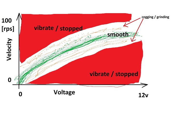
Remember that the voltage AND velocity for an open loop, no feedback algorithm for a particular unknown motor work in a very narrow band.
Untitled
The best way to handle this is to attach two potentiometers to A0 and A1 or whatever analog signal input pins you are using, and scale them to the min/max voltage and velocity and read within the open velocity loop, and set the voltage and velocity within each loop iteration, then start tuning the motion manually.

Turn the voltage knob up a bit, turn the velocity knob a bit until you get some movement, then start slowly increasing both. Also, depending on the motor, some motors cannot just start turning when you apply fixed voltage, you need to “spin them up” first following that green curve, else if you just hit them with some voltage and try to spin them, you are just going up and down that narrow velocity green to orange region and eventually hit the red above and below and the motor stops, and the back EMF shoots into the driver and if your motor is really spun up to the top at a very high speed you kill the driver, because most hobby driver boards have absolutely no protection for all that mechanical energy which suddenly converts to EMF and uses the naked driver as a brake.

If I get some more time I’ll post sample code. Using manual physical knobs for voltage and velocity tuning is superior to any Serial command tuning because it gives you immediate haptic feedback.

Below is the STM32 code loop, to give you an idea.

void loop() {

  analog_read_A0 = analogRead(PA0);
  analog_read_A1 = analogRead(PA1);
 
  target_velocity = float(map(analog_read_A0, 0, 4096, 0, 10000))/100.0;
  
  target_voltage = float(map(analog_read_A1, 0, 4096, 0, 1200))/100.0;

  motor.voltage_limit = target_voltage;

  motor.move(target_velocity);
}
4 Likes

Yes, I was running open loop control examples (position and velocity). I had just assigned just pin numbers according to the configuration of my board without changing anything in the example code.

Thankyou for patiently replying. I will try attaching potentiometers in order to manually tune the motion manually. I will update soon.
Thanks again

Hi everyone

I’m trying to run velocity control example with the encoder from simpleFOC (examples).

My hardware configuration:

  • Arduino Uno R3
  • simpleFOC shield
  • iPower GM4108H-120T 24N22P
  • 12V, 3.3A power supply
  • Simple_FOC library
  • PciManager library
  • pin assigment (9,10,11,8)
  • amt103v (A2,A1, 2048,A0) - resolution PPR - 2048 *(0,0,0,0)
    I have ran the encoder test and was able to print angle and velocity, also tried open loop position and velocity control with same pin configuration both examples worked just fine except motor over heating issues.

When I am trying Closed loop examples with the encoder I am getting the following errors:

MOT: Monitor enabled!
MOT: Init
MOT: Enable driver.
MOT: Align sensor.
MOT: Index search...
MOT: Success!
MOT: Failed to notice movement
MOT: Init FOC failed.
Motor ready.
Set the target velocity using serial terminal:

This link says its an encoder related issues but all my connection seem to be proper.
My code:

#include <SimpleFOC.h>
// software interrupt library
#include <PciManager.h>
#include <PciListenerImp.h>

// BLDC motor & driver instance
BLDCMotor motor = BLDCMotor(11);
BLDCDriver3PWM driver = BLDCDriver3PWM(9, 10, 11, 8);


// encoder instance
Encoder encoder = Encoder(A2, A1, 2048, A0);

// Interrupt routine intialisation
// channel A and B callbacks
void doA(){encoder.handleA();}
void doB(){encoder.handleB();}
void doIndex(){encoder.handleIndex();}
// If no available hadware interrupt pins use the software interrupt
PciListenerImp listenerIndex(encoder.index_pin, doIndex);


// velocity set point variable
float target_velocity = 0;
// instantiate the commander
Commander command = Commander(Serial);
void doTarget(char* cmd) { command.scalar(&target_velocity, cmd); }


void setup() {

  // initialize encoder sensor hardware
  encoder.init();
  encoder.enableInterrupts(doA, doB); 
  // software interrupts
  PciManager.registerListener(&listenerIndex);
  // link the motor to the sensor
  motor.linkSensor(&encoder);

  // driver config
  // power supply voltage [V]
  driver.voltage_power_supply = 12;
  driver.init();
  // link the motor and the driver
  motor.linkDriver(&driver);

  // aligning voltage [V]
  motor.voltage_sensor_align = 3;
  // index search velocity [rad/s]
  motor.velocity_index_search = 3;

  // set motion control loop to be used
  motor.controller = MotionControlType::velocity;

  // contoller configuration 
  // default parameters in defaults.h

  // velocity PI controller parameters
  motor.PID_velocity.P = 0.2;
  motor.PID_velocity.I = 20;
  motor.PID_velocity.D = 0;
  // default voltage_power_supply
  motor.voltage_limit = 6;
  // jerk control using voltage voltage ramp
  // default value is 300 volts per sec  ~ 0.3V per millisecond
  motor.PID_velocity.output_ramp = 1000;
  
  // velocity low pass filtering time constant
  motor.LPF_velocity.Tf = 0.01;

  // use monitoring with serial 
  Serial.begin(115200);
  // comment out if not needed
  motor.useMonitoring(Serial);

  // initialize motor
  motor.init();
  // align sensor and start FOC
  motor.initFOC();

  // add target command T
  command.add('T', doTarget, "target velocity");

  Serial.println(F("Motor ready."));
  Serial.println(F("Set the target velocity using serial terminal:"));
  _delay(1000);
}

void loop() {
  motor.loopFOC();
  motor.move(target_velocity);
  //motor.monitor();
  command.run();
}

I have also tried motor.monitor() in loop, its giving me all 0 0 0. I would highly appreciate any of you helping me regarding this. Thanks in advance. ( I have followed this @Nuno thread and @Raj_Sekhar )

Regards

Raj

Hey @Raj_Sekhar1,

In your case the encoder is not being wekk detected and your program will not work. The reason is that the encoder pins A and B are connected to the analog pins A2 and A1. This is not a big problem in general, but Arduino UNO does not have interrupts on these pins, so you will need to use the PciManager for them too, not just for the index pin.

So you have two options:

  1. Assign the encoder A and B channels to the pins 2 and 3 of the arduino, since these pins have hardware interrupts. Then the only change in the code will be:
Encoder encoder = Encoder(2, 3, 2048, A0);
  1. Use PciManager for channels A and B of the encoder as well.

// If no available hadware interrupt pins use the software interrupt
PciListenerImp listenerIndex(encoder.index_pin, doIndex);
PciListenerImp listenerA(encoder.pinA, doA);
PciListenerImp listenerB(encoder.pinB, doB);

...
void setup(){
  // initialize encoder sensor hardware
  encoder.init(); 
  // software interrupts
  PciManager.registerListener(&listenerA);
  PciManager.registerListener(&listenerB);
  PciManager.registerListener(&listenerIndex);
  // link the motor to the sensor
  motor.linkSensor(&encoder);
...

Now both of the solutions will work but I would suggest you to go with the first one. Because the software interrupts are slower than the hardware ones and since Arduino UNO is not a powerful microcontroller this will improve your performance.

The other suggestion I would like to give you is to lover the PPR number in on your ATM103 sensor. When you open it you have 4 small slider switches which determine the PPR of the sensor. Since Arduino is not powerful, I’d suggest you to make the PPR around 500.
The rule of thumb is: if you wish to have very smooth slow motions than 2000+ PPR makes sense, if you wish to spin your motor fast then go to under 500.

How to achieve this using single potentiometer. Hi Sir, Currently I am working on ESC for electric cycle motor (36V 250W 10 pole pair) in open loop velocity mode i can not use two potentiometer, I can use only e bike throttle. I build my won Driver based on IR2103 MOSFET driver.

I have no idea. I dont think its possible.