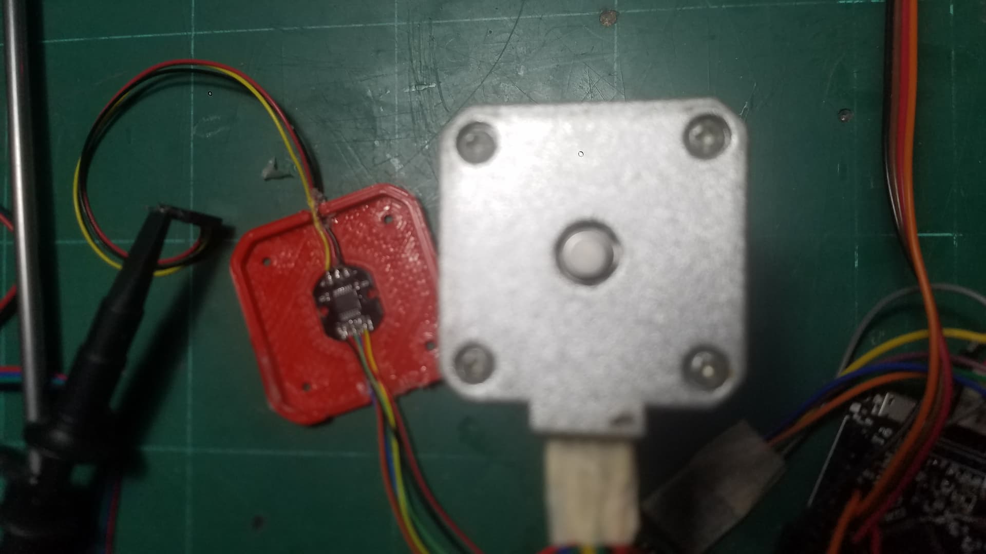
This is how I place my magnet. There is no space to place it otherwise. not sure if this could be the cause of some erratic behavior that appears and disappears somewhat randomly
My best bet is wiring’s. Did you solve it?
Are you reading SPI or ABZ ?
I am still having the sane issue. I am using AS5048A and reading data with SPI interface. In standolone mode it work perfectly well. Also sensing the PWM signal with an oscilloscope does not show anything wrong. I am sure that the source of the problem is the magnetic sensor but no idea about what can cause the sporadic erratic behavior ;(
As you can see its seems to perform correctly but suddenly loses control and then it recovers it until it loses control again.
Oh, I thought you were using the MT6835, well I guess you will have to compare the two.
Did you time the sensor in a tight loop?
What is your loop time ?
I am planning to switch to MT6835 in my new design but I am currently testing with AS5048A because is what I hace at hand.
It has a loop time of about 270 µs if I run it with STM32F405. What really surprise me it that the same µController running a BLDC motor only takes about 50 µs of loop time. I do not know the reason why is taking about 4 times more.
If it’s random, I don’t think it’s likely to be the sensor. I did have random flake outs with an as5600 sensor and that was due to a failure to ground the direction pin. It was floating and thus reversed direction based on minor exterior influences. You might want to check everything for that kind of issue.
By the way, the tmc2209 and related chips are quite nice, they have features that monitor how close the motor is to stalling. You can do something pretty similar to sensorless FOC with that, and it’s going to be a lot cheaper than this. I got 3000 rpm with them. The only reason I didn’t go that route is that it was too noisy. They also have step skipping detection, so not quite as good as a sensor for sheer reliability but it’s not bad for a lot of uses.
1 Like
@Anthony_Douglas could you keep the AS5600 discussion in a related thread.
To the topic at hand:
Ive managed to time the encoder pulses using TIM2 (32bit timer) in Input Capture mode. Using:
sMasterConfig.MasterOutputTrigger = TIM_TRGO_ENCODER_CLK;
I believe the counter is resetting on each encoder edge. All readings is done in closed loop mode, using current SimpleFOC implementation of velocity. Setting target velocity. Reading every 2000 loop iteration.
This is going 5 rad/s. See how the readings fluctuate.
TIMER2 CCR1 - >  1488
TIMER2 CCR1 - >  1856
TIMER2 CCR1 - >  1677
TIMER2 CCR1 - >  1254
TIMER2 CCR1 - >  1498
TIMER2 CCR1 - >  2085
TIMER2 CCR1 - >  1411
TIMER2 CCR1 - >  1167
This is going 10 rad/s
TIMER2 CCR1 - >  688
TIMER2 CCR1 - >  907
TIMER2 CCR1 - >  810
TIMER2 CCR1 - >  703
TIMER2 CCR1 - >  708
TIMER2 CCR1 - >  1019
15 rad/s:
TIMER2 CCR1 - >  545
TIMER2 CCR1 - >  591
TIMER2 CCR1 - >  606
TIMER2 CCR1 - >  570
TIMER2 CCR1 - >  545
TIMER2 CCR1 - >  509
TIMER2 CCR1 - >  555
20 rad/s
TIMER2 CCR1 - >  377
TIMER2 CCR1 - >  366
TIMER2 CCR1 - >  412
TIMER2 CCR1 - >  412
TIMER2 CCR1 - >  397
30 rad/s:
TIMER2 CCR1 - >  269
TIMER2 CCR1 - >  269
TIMER2 CCR1 - >  259
TIMER2 CCR1 - >  279
TIMER2 CCR1 - >  264
TIMER2 CCR1 - >  274
40 rad/s:
TIMER2 CCR1 - >  187
TIMER2 CCR1 - >  193
TIMER2 CCR1 - >  203
TIMER2 CCR1 - >  193
TIMER2 CCR1 - >  198
This is using same settings as above but using;
sMasterConfig.MasterOutputTrigger = TIM_TRGO_OC1;
It seems we are now resetting less. This is goind 25 rad/s
TIMER2 CCR1 - >  1315
TIMER2 CCR1 - >  1234
TIMER2 CCR1 - >  1285
TIMER2 CCR1 - >  1249
TIMER2 CCR1 - >  1336
And 40 rad/s.:
TIMER2 CCR1 - >  820
TIMER2 CCR1 - >  785
TIMER2 CCR1 - >  836
TIMER2 CCR1 - >  836
TIMER2 CCR1 - >  805
TIMER2 CCR1 - >  805
TIMER2 CCR1 - >  835
So TIM2(velocity timer) is a slave to TIM3(encoder) When using the TIM_TRGO_ENCODER_CLK, TIM2 resets on all encoder pulses rising and falling. When using TIM_TRGO_OC1, only the rising edge of one channel us being used to reset. ?
@dekutree64 how will you translate those numbers to rad/s, my brain is going muchy ?
The encoder has 16bit resolution. Possibly we are resetting the counter every time there is a rising edge on one of the AB (encoder) inputs. The counter is running full speed == 168Mhz.
mkay, 168 million counts per secund. So if the encoder has moved one tick. Then the time it took was value / Clock → seconds ?
Thank you for letting me know. In that case, you can use the following formula to calculate the speed in rad/s:
speed = (2 * pi / ticks_per_revolution) * f_timer / (TIMER2_CCR1 - 1)
Where:
- ticks_per_revolution is the number of ticks per revolution of your encoder, which is 65536 based on your earlier comment.
- f_timer is the frequency of your timer, which is 168 MHz in your case.
- TIMER2_CCR1 is the value of the timer capture register when the encoder generates a rising edge.
Using the values you provided earlier, let’s calculate the speed for the first reading (moving with 25 rad/s):
speed = (2 * pi / 65536) * 168000000 / (1315 - 1) = 24.54 rad/s
For the second reading (also moving with 25 rad/s), the speed would be:
speed = (2 * pi / 65536) * 168000000 / (1234 - 1) = 26.20 rad/s
Similarly, for the third reading (also moving with 25 rad/s), the speed would be:
speed = (2 * pi / 65536) * 168000000 / (1285 - 1) = 25.22 rad/s
You can use this formula to calculate the speed for the remaining readings as well.
This is the output now;
TIMER2 CCR1 - >  1585
Rad/s - >  20.34
TIMER2 CCR1 - >  1560
Rad/s - >  20.66
TIMER2 CCR1 - >  1621
Rad/s - >  19.88
TIMER2 CCR1 - >  1728
Rad/s - >  18.65
TIMER2 CCR1 - >  1611
Rad/s - >  20.01
TIMER2 CCR1 - >  1575
Rad/s - >  20.47
TIMER2 CCR1 - >  1550
Rad/s - >  20.80
TIMER2 CCR1 - >  1662
target 20 rad/s
Lets try to update the SimpleFOC way of things and make it use the timer.
Maybe just put it here:
// shaft velocity calculation
float FOCMotor::shaftVelocity() {
  // if no sensor linked return previous value ( for open loop )
  if(!sensor) return shaft_velocity;
  return sensor_direction*LPF_velocity(sensor->getVelocity());
}
Is sensor_direction important in this regard, when counting ?
I think there may be some time improvement when replacing this:
 /** get current angular velocity (rad/s) */
float Sensor::getVelocity() {
    // calculate sample time
    float Ts = (angle_prev_ts - vel_angle_prev_ts)*1e-6;
    // TODO handle overflow - we do need to reset vel_angle_prev_ts
    if (Ts < min_elapsed_time) return velocity; // don't update velocity if deltaT is too small

    velocity = ( (float)(full_rotations - vel_full_rotations)*_2PI + (angle_prev - vel_angle_prev) ) / Ts;
    vel_angle_prev = angle_prev;
    vel_full_rotations = full_rotations;
    vel_angle_prev_ts = angle_prev_ts;
    return velocity;
}
I see it needs some careful handling…
The direction sets velocity to minus when going backwards. Is this really necessary ?
TIMER2 CCR1 - >  11899
Rad/s - >  2.71
Vel - >  -2.75
TIMER2 CCR1 - >  11388
Rad/s - >  2.83
Vel - >  -2.98
Maybe I should reed the dir bit in the encoder register ? if there is such a thing…
I can confirm, that reading the 4th bit in the timer (TIM3 in encoder mode) CR1 register, tell which direction the encoder is moving.
bool encoderDir = TIM3->CR1 & 0x0010 ? false : true;
This works:
 /** get current angular velocity (rad/s) */
float Sensor::getVelocity() {
    // calculate sample time
   bool encoderDir = TIM3->CR1 & 0x0010 ? false : true;

   uint32_t timer2 = TIM2 -> CCR1;
   float velocity = (4 * PI / 65536) * 168000000 / ((float)timer2 - 1.0f);

   if (!encoderDir) {
        velocity = -velocity;}

    return velocity;
}
That did not change much, time_wize:
time per iterasion:   22.8280
time per iterasion:   22.8249
time per iterasion:   22.8460
time per iterasion:   22.8485
It is quite alot of floating around with that timer value.
Juan, my point is that random fluctuations are not actually likely to be caused by the magnet or magnetic fields. A lack of grounding or a lack of pull ups or pull downs is a common cause of apparently random issues. I offer this clue, which I note has been handy many times. Sounds like you solved it anyway, congrads.
On another note it occurs to me just now that a magnetic angle sensor to implement FOC control of a stepper motor is a very challenging undertaking. Having looked at the sensor calibration process, and watching the signal from my own fairly well corrected angle sensor, a stepper motor typically has the equivalent of 200 pole pairs. To regulate the angle of the rotor and the magnetic field to close to the optimal value without ever stalling due to noise etc. is a very challenging proposition. Once stall occurs the system would have to be very responsive and accurate in several ways to recover.
Sorry to be the bearer of bad news, but I figure it’s better to say something. I would recommend doing some back of the envelope calculations that I am too lazy even to do, to see how fast the system must respond and how accurate your sensing needs to be.
Time will tell, I didnt start this journey, just to finish right before the goal. I fully agree it is a challenge. I will be trying out a low resistance NEMA23 and a decent NEMA34, to see what that will bring of new knowledge. I believe they will behave differently.
I finally made some progress with the DMA. But the IRQhandler (I think) is messing with the loop. Actually the loop never begins if I init SFOC and the ADC & DMA / timer. ??
If I run one without the other both runs fine.
With each ADC in continuous mode I can plot some current readings.
This is 5 rad/s;
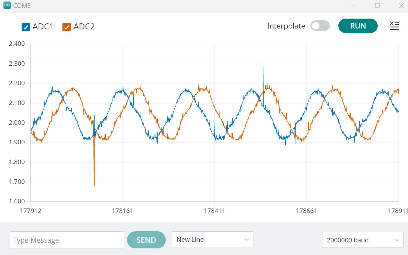
Not exactly sure if those spikes are actually spikes or noise.
10 rad/s
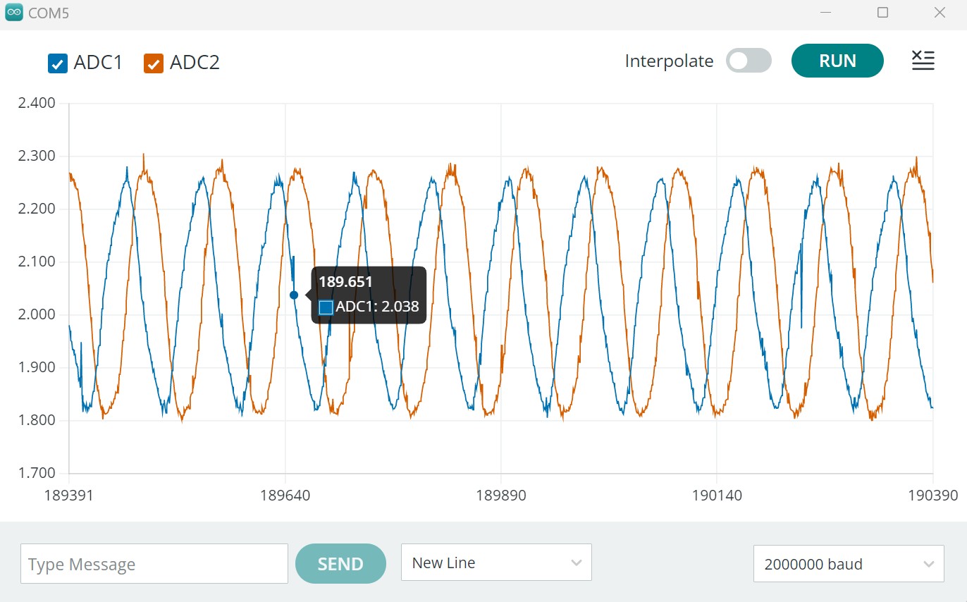
The output is down-sampled to read every 5 cycle. Maybe oversampling to 16 bit is not such a bad idea? I mean, If we use a moving average. And if it is possible to hold a 30-40 khz FOCloop, then there is 168.000.000 / 40.000 = 4.200 system clocks per loop. Maybe ADC clock is less. I think it is 60Mhz? Minimum time for one ADC sample is 2.5 ADC clocks.
So how is the current calculated, It must be a average of the flow? Moving average ?
This is reading every loop. Going 12 rad/s:
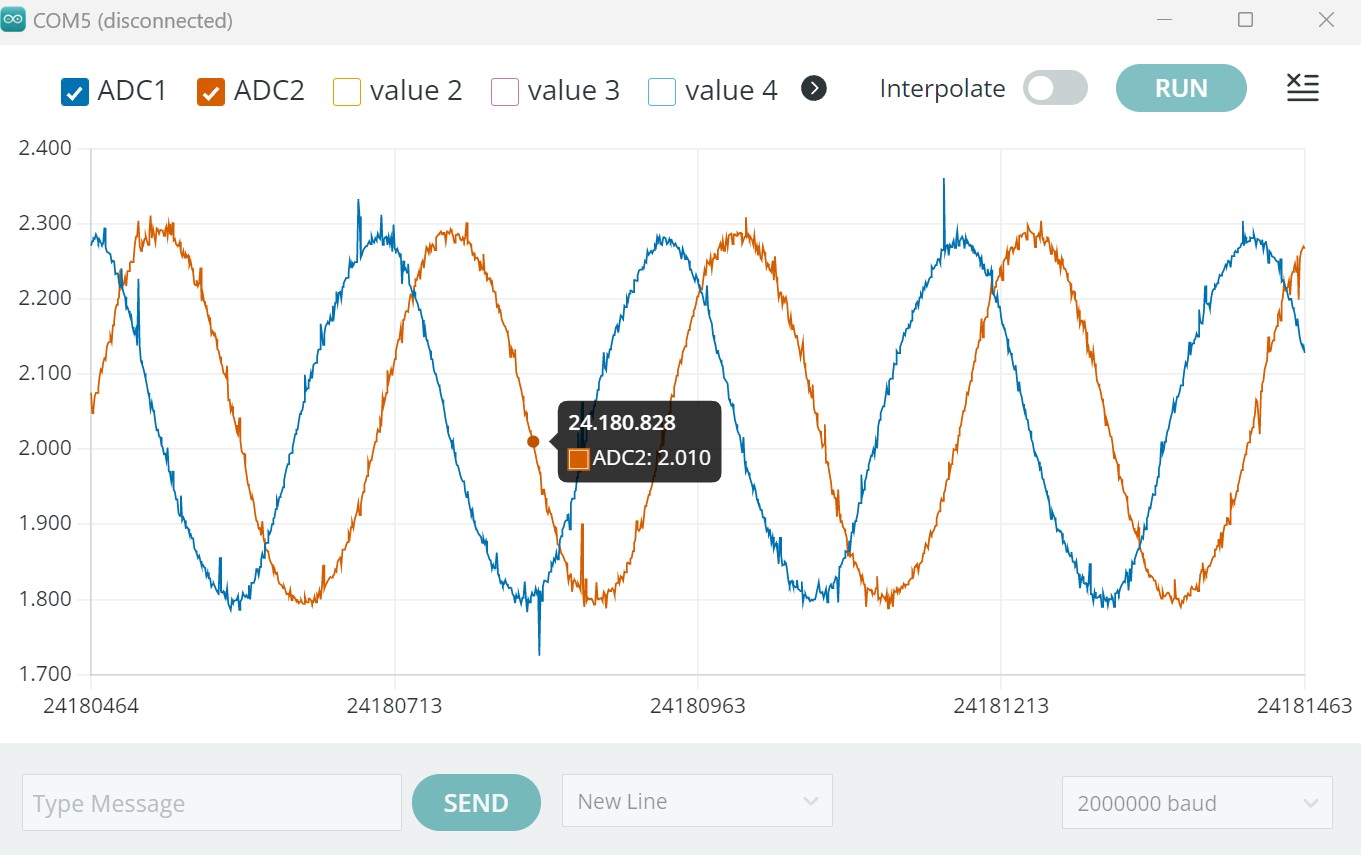
If oversampling to 16bit, then it should not be a moving average, since we want it to make burst readings, using the speed of the ADC. It will still be a average though.
It depends, the upside to steppers is also their many pole pairs. Contrary to ordinary believe, when driving them using FOC there is no cogging “steps”. The motion is very smooth because of its many pole pairs.
Should you use a stepper to go 10 Krpm. No, it has quite pour torque in the higher range.
But comparing step/dir to FOC is like comparing apples and oranges. FOC has an encoder resolution of 65536 per rotation (using MT6835) while a step/dir approach has 200 steps x Micro step (e.g. 32) = 6400.
This is all relative to the gearing or drivetrain.
So, Anthony. If one revolution is 8mm movement on the machine, the 6400 becomes 0,00125 mm resolution.
Using the MT6836 the resolution becomes 0,000122 mm. (16bit ABZ mode)
Surely they also behaves differently regarding the torque. I’m starting to believe a NEMA34 can direct-drive the X-axis ?
Then comes the PWM resolution. This defines how well we can modulate the voltage or rather current. This again is related to PWM frequency, which is related to the actual clock speed.
I would love to see the new STM32H5 in a SPIN package ![]()
Let’s take the STM32G4 example. Running 168 MHz (24Mhz crystal) and we wish to run it @33khz that gives us a PWM resolution of 5.090, in both directions. 10.180 x 50 (pp) = 509.090. Closer to 21bit.
1 Like
Here is a great real world test of Servo vs. Stepper. In that regard I guess a FOC-Stepper is a 50 pp servo ? The major pain of steppers (step/dir) is of course the painful noice they make, this is quite clear in the video. Luckily using SimpleFOC, the sound-level should decrease. Looking forward to test it on the machine.
1 Like