How about reading the BEMF? @Antun_Skuric should it be taken into account when choosing ADC sampling paradigm?
You’re talking about current sensing, right?
That’s a differential measurement across a shunt (or using Hall effect sensor) and BEMF doesn’t matter for it.
If you want voltage sensing to sense BEMF this needs a different hardware configuration and has different timing rules (based on the commutation rather than the PWM)…
If you want to do both current and voltage sensing it will be complex handling the timings on the same ADC - either use different ADCs or just use the current sensing timings, which will be much faster than the voltage sensing, and downsample in software.
Right, never mind that, the voltage divider on VM is too far away from the phases.
Maybe this ADC watchdog is a handy feature. Can it be changed on the fly? Could it trigger the PWM output to go low?
If that is the case, then it can serve as a hardware controlled current limiter.
I guess a watchdog has some interrupt handler, in which case we can trigger TIM1/TIM8
In theory this will offload the MCU from doing any current calculations?
Let’s say we have 24v on VM. Using current implementation where the duty-cycle is limited to phase voltage calculated by phase resístanse, the motor does not take advantage of the voltage potential.
If we are able to exceed the voltage limit calculations and catch the current spike, suddenly the motor becomes way more responsive. This enables true torque control, whereby we can set an ultimate upper “torque threshold” or modulate it.
From the TIM1/TIM8 perspective, we will be jumping through time or skipping ticks, to force the counter to overflow?
Are you getting my drift ?
Let’s go deeper.
The CORDIC will be sending voltages to the phases based on the electrical angle. If those voltages are limited by ohm, we do not utilize the voltage potential. The reason for limiting the voltage by ohm, is to not burn down the motor, since sending 24V to e.g. 3 ohm resistance will reach 8 amps ( much more for low resistance steppers). Also, the coils are not able to change current that fast, so because of the inductance it will get stuck trying to change that much current.
We just want it to apply the rated torque and then get on with it.
What if the torque component then get dynamic. A.k.a The final frontier. In praxis this will signify changing the watchdog value when more torque is needed to move forward in the desired speed?
This could potentially slow down the machine, since we then push more current through, so larger ripple, but the machine will maintain its course set out by the mainframe. Until it hits the ultima upper limit, where the controller should stop all motion, because it is a potential show stopper, hitting a end stop or some obstacle it can’t overcome…
Usually the highest torque demand is when moving from standstill, luckily we will want to ramp the motion, so in that scenario the speed demand is low. When reaching target speed the torque demand should decrease, unless you are milling some ornament in Ali ![]()
The challenge is turning down the torque component when the torque demand is diminishing… the MCU should therefore strive to move with lowest possible torque. The velocity component will be available by reading the secondary timer constantly timing the encoder pulses or edges.
Isn’t that what the velocity PID already does? It fiddles the torque up and down as necessary to maintain the target velocity, while keeping within the specified current limit. Or is it different with steppers? I’ve only used them with open loop drivers.
Yes, I think you are right. If it works, big if. The proposed method will offload the MCU and we can achieve even higher FOCloop frequency. Or rather the current sampling + calculations, will not slow down the loop.
@Candas1 im starting to think that the low-priority ADC channels should be injected in this scenario, since we want to monitor current as often and fast as possible, while also sometimes, maybe every 20 iteration or less, do thermistor and voltage divider reading ?
From what I gather, the injected channels have a separate trigger and buffer ?
@dekutree64 so you are saying the PID controller should control the ADC WDT → register ?
Naturally triggering the ADC WDT is not enough, it has to be reset, when the PWM timer is forced. I guess the WDT handler will clear the flag, when it’s done doing it’s thing.
Regarding the voltage divider, it could also be tied to a ADC WDT… as can the Thermistor.
So it sounds to me like what you want is implemented by using velocity mode with current limit - by setting motor phase resistance and KV values.
In terms of the ADC sampling, there’s not much point in sampling more often than the main loop frequency, as the values aren’t used more often.
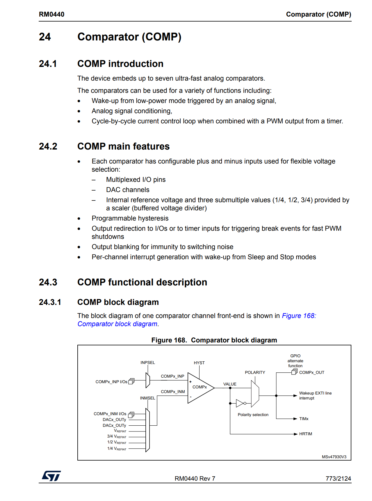
Of course if you use the analog watchdog then there might be a use for it, but if it’s current limiting you’re trying to achieve (for example as a protection feature) there’s a better way to do it using the chip’s comparators in combination with the TIM1 break inputs. This will be much faster than any interrupt based solutions which have to go through the ADC, the watchdog, the interrupt controller, the software interrupt routine and then to the timer…
Page 653
Comparators (COMP)
Page 773
Great @Juan-Antonio_Soren_E that’s looking incredible!
If I may derail the conversation briefly could you post you open loop control code or the minimal code to bring up the gate drivers? Would greatly appreciate it as still haven’t been able to get life out of my gate drivers although it very much looks like there something wrong with the high side gate drivers as the VDS protection is triggered when I try to drive it.
Best of luck with the current control would be amazing to get some fancy torque control going. Looking forward to see what you get upto.
Yes. In my case I use cc4 as a trigger.
Injected adc even have offset registers.
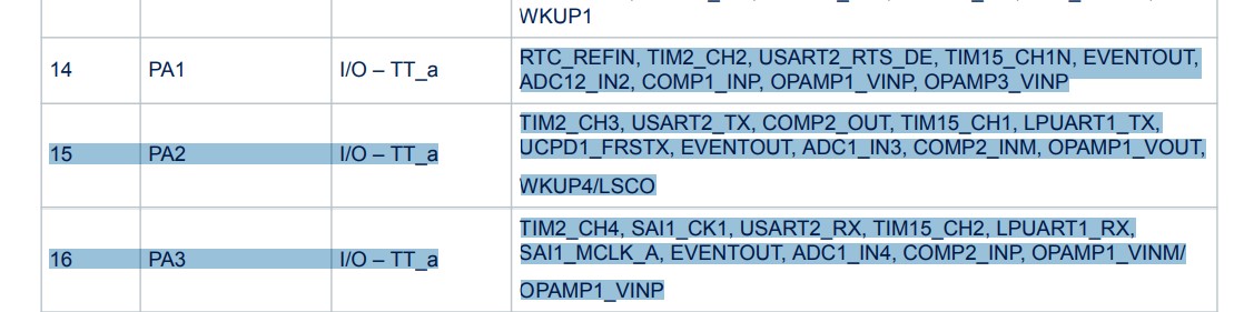
Regarding the COMP inputs, then it should be possible. I have the two amplifiers on PA1 and PA2 but PA3 is broken out, so I could redirect PA2 to PA3.
So you use the DAC to set the threshold ? As a internal reference ?
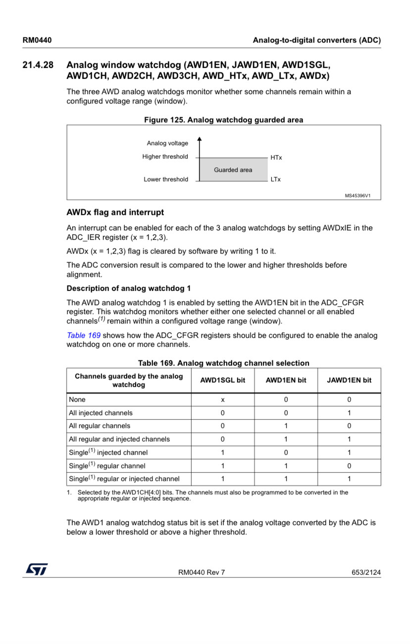
An analog watchdog operates in a similar manner. Only instead of monitoring a timer, it monitors an analog input channel. At initialization, you tell the watchdog what analog thresholds to monitor for. If a converted value on an analog input passes one of these thresholds, it will fire an interrupt for you to process the signal sample. This means you don’t have to write code to continuously poll the analog inputs and check their levels. It is all handled autonomously in the background by the analog watchdog circuitry.
The analogue watchdog on STM32 is simply a means of generating an interrupt when some external voltage drops below or exceeds a programmable threshold level. This is done without software intervention when the ADC conversion s configured to free-run, so if the application only needs to respond to thresholds, this can be implemented with zero software overhead for ADC polling.
Was looking at the tuning again. Changed to 24v 15a PSU

And for my next trick, I will try the CORDIC
Field-Oriented-Control Stepper driver | Hackaday.io
Show us some love ! ![]()
100 rad/s → 954 rpm

OK, ive managed to “install” the CORDIC, using the float “angle_el”. There does not seem to be a time performance increase or decrese, mutch. But the overall performance is better. Less noise.
time per iterasion:   23.2295
time per iterasion:   23.2306
time per iterasion:   23.2301
time per iterasion:   23.2298
time per iterasion:   23.2303
Do you think a 34NEMA can drive a bike ?
Maybe top speed 1500 rpm ish ![]()
I am having problems when placing the magnetic sensor in a NEMA 17 Stepper Motor because it seems that at times it loses the signal with the magnet and causes it to lose control in closed loop control. In your setup, how do you place the magnets to make it work?
In my experience, the sensor is very sensitive to any magnetic field. Maybe it is too close to the coils. I think @runger had this issue with a miniature outrunner ?
As you may have seen, I was forced to use some not so ideal radialy magnetized neodymium magnet put on the side and glued with super epoxy … after the calibration it works