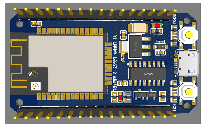
ESP32-S AI-Thinker Dev Board Schematics/PCB development board schematics, if anyone feels the need to fabricate their own board.
The board is of my design, and all components are currently in stock. I had the need for this one to work on my comm module. Feel free to change/whatever.
I put the latest ESP32-S, which amazingly is still in stock. SMH. It’s also got a balun for an external antenna, which is nice if you want to extend your range.
This board includes my hardware fixes to the bugs in the silicon which show when you program or startup the board, which are not included on other board, including the official adafruit, etc, or aliexpress, whatever, that’s why I needed my own design. These were recommended by espressif and were not included in the other boards floating around because they make the other board more expensive. Also unlike the other boards this one is a 4-layer with the signals locked inside l1 and l2 between top/bottom ground planes. The mcu plate is also grounded for better heat dissipation with vias.
As usual, this is for my own work so it may not fit your use cases. Caveat emptor.
100uF tantalum capacitor (very expensive) to prevent brownouts when powered by USB (the RF consumes a lot of power especially if you connect an external antenna and set as an access point and it starts pinging the leaf nodes, need high surge current and high ripple current capability), and a 10uF ceramic capacitor with a resistor to hold EN low while uploading code, since it appears the board does not properly hold the EN low long enough to complete the handshake and code uploading breaks. There were recommended by espressif but make the board bigger and more expensive. The tantalum capacitor is more expensive than the ESP32 module Edit: I cost the board, it’s about $25 if you run 10 of those.
Love it! And it must feel good to get a board produced
I have my first one since ages in production at PCBWay right now… and it took 3 iterations on the BOM to get it to the point where all the components were available…
I had generally poor experience with PCBWay. They can’t guarantee anything, and the support staff is overall poorly informed and have no decision power. I am not bashing PCBWay, it’s relative. With JLC it’s WYSIWYG. If it’s in stock and in the database, you got it. They could even hand-solder for me, which usually is unheard of for small orders. And the staff is knowledgeable and could do things for me, they even pulled boards from the production line or re-shipped and redirected shipments (at their expense!). From design to door even with the shortage and covid and what not it’s still about 10 business days. JLC have their own problems but comparatively it’s better.
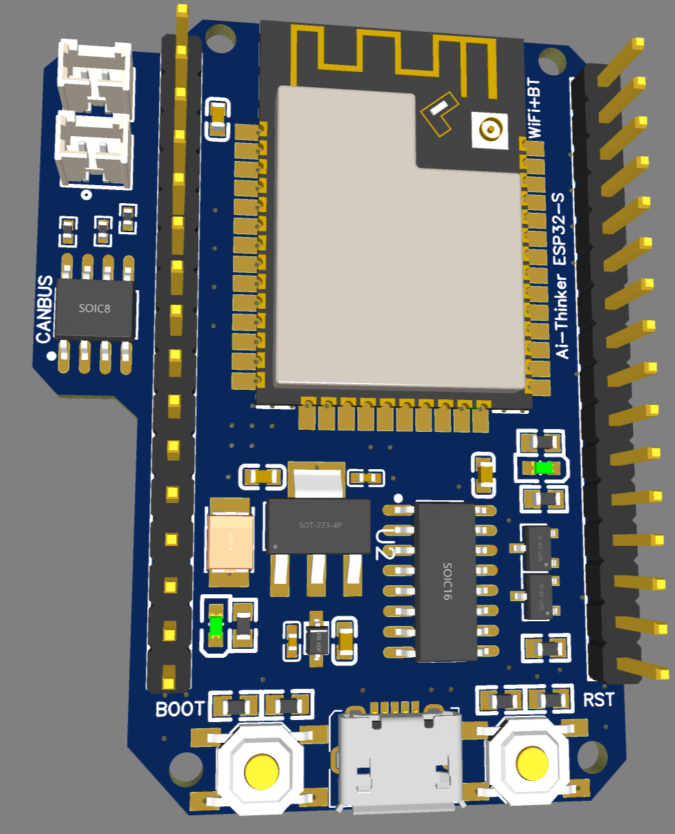
Edited the board, replaced extended components with basic in stock and also added CANBUS transceiver. Will fab today and report if the board actually works. This can be used as a central command/control to receive via wifi or BT and control motor boards via CANBUS.
Edited the board even more, replaced the MCU with 32D. For the life of me could not make the AI-Thinker boardlet to load the code. Fabbed.
The board works, here is proof. Basic blinker, I added an LED to IO2. If anyone needs ESP32 with built-in canbus to receive WiFi or BT commands and pass to multiple motor boards connected to canbus, this is your answer. Connects/loads code without the need to push/hold any buttons. Very convenient if you do development and debugging.
will this board can be easily programmed through the arduino ide having esp32 wroom library installed which we usually used to programme the other esp32 devkit development board.
please do reply.
Thanks for your reply sir,
your board is 2layer or 4 layer?
What is the use of “Download” and “CAN” in the schematic and the peripherals outside the schematic, please explain?
Thanks
Sir 3 question generally i would like to ask, suppose i have a 1 side pcb board ie having all components through hole and i would like to make a SMT pcb so can I directly replace through hole components eg resistor capacitor and ic with the smt components of exact similar electrical parameter. So do this thing will i get the better result as compared to old single layer board?
If i have to find the pin to pin replacement of IC( suppose if some ic is not available in market) then which electrical parameters should I look for correct pin to pin match of any IC?
I am looking for best OPAMP IC used to amplify photodiode signal and has capability to stop the drift eg if out of OPAMP is 3.203 volt then it should remain 3.203 volt contant the value after decimal .203 should not fluctuate so for this i am locking for best ic , please help me to stop the drift put of the amplified signal of photodiode?
You need the exact part. You cannot do replacement with similar parts.
I cannot help you with that. My hardware knowledge, though rather extensive, does not span across such niche topics. You may be better off asking such questions on a much more generic forum such as the Arduino forum here
Just generally speaking there is not really a reason why the design would be “better” just because it is SMD based rather than through-hole…
You’d have to specify a lot more about the design to really say that. I think there is a likelyhood of high-speed designs being “better” in SMD, but there’s a lot of additional factors to consider. For low-speed designs and prototyping in general the through hole components can have their advantages. SMD is much harder to hand-solder.
I’d say one of the main reasons to go for SMD is component availability (I guess most ICs aren’t even made in through hole versions these days) and/or because you want automated assembly.
But I’d be careful about assuming that a design would somehow become “better” just by being SMD.
What’s actually wrong with your through hole design?
will your esp32 board works in the same manner if it is to be designed in 2 layer pcb instead of 4 layer? , sir what are the components attached outer side of the schematic borders in your design?
Hi sir,
Suppose instead of using ( Ai Thinker ESP32-S WiFi+BT SoC Module) can i also use other esp32 chips like ESP32-WROOM-32D 4M 32Mbit Flash WiFi Bluetooth Module Espressif ESP32-WROOM-32D 8M 64Mbit WiFi Flash Bluetooth Module
Espressif ESP32-WROOM-32E is a Wi-Fi+BT+BLE MCU
etc .,if i designed the board with other esp32 chips with same peripheral circuits as in your schematic and programme using arduino ide will micro usb will the programme be flashed in that chip???