Hello peoples,
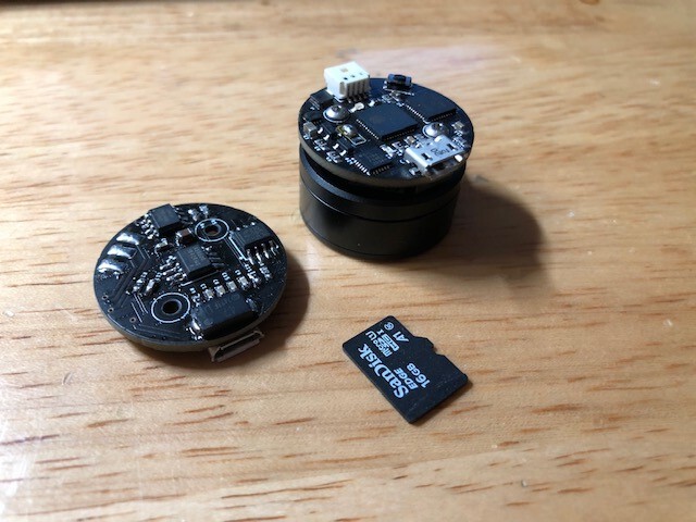
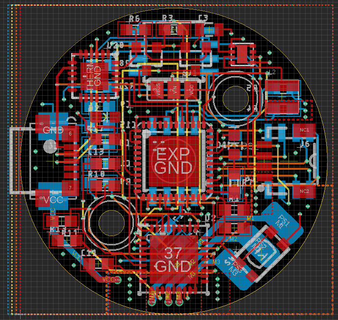
I designed a ESP32 driver using the DRV8313, AS5600 and Canbus transceiver for a robotics project im working on, but I’m having issues with the motor fine tuning…
I’ve been trying to play with the PID variables in full_control_serial.ino for a while, but I can seem to eliminate this little twitch that occurs when the motor is sitting at the setpoint.
Has anyone had a similar issue? (I’ve already swapped the pwm library with the one in the github docs)
Please see the video link below!
Video_Link
//-----------------------
// velocity PI controller parameters
motor.PID_velocity.P = 0.2;
motor.PID_velocity.I = 20;
motor.PID_velocity.D = 0.001;
// maximal voltage to be set to the motor
motor.voltage_limit = 6;
// velocity low pass filtering time constant
// the lower the less filtered
motor.LPF_velocity.Tf = 0.01;
// angle P controller
motor.P_angle.P = 20;
// maximal velocity of the position control
motor.velocity_limit = 40;
//----------------------------------
right now the main loop is running @1Khz
1 Like
Very nice little driver!  Are you using the ESP32 pico?
Try putting D to 0 and TF to 0 and a relative high I, which you already have. Usually what I do to remove that oscillations.
Thanks David,
Yea its the pico
I tried that.. but no luck. I get major oscillation if i do that:
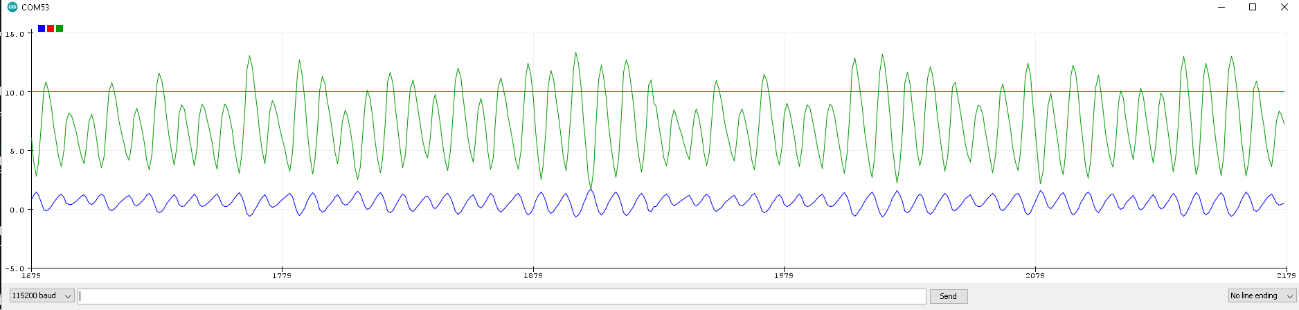
My issue isnt so much an oscillation, as it seems to be a miniature spike.. the motor.voltage_q ( blue ) in my graph slowly increases( 0.25-1 second) the effort level until ( as i understand ) until it gets to a voltage threshold where it moves the rotor, and pops back up to the setpoint instead of a gradual motion.
the total displacement is only ~1degree, but its enough to annoy the hell out of me lol
right now the setpoint and the target are ~0.01 radian off, but its enough for the effort to build.. is there a way to create an acceptable error in the pid software, so that if the target setpoint and the shaft angle are within xyz degrees, the PID essentially turns off until the next command is issued?
ideas?
 I know exactly how you feel.
I see in your video that this behavior doesn’t happen always. Am I correct? if so usually it’s harder for motors to hold a position because of the cogging. So if you motor has for example 11 poles, there will be 11 places that the rotor has a bit of trouble holding nicely.
it jumps in every location that i’ve tried… sometimes it will settle after a while.
its just hard to see in the video.
i can eliminate the jump… by getting rid of the I&D terms… but i need those for what i’m doing.
its a gimbal motor with 7 pole pairs… but i’m sure it has a little cogging… ill swap the motor and see if there’s any change… process of elimination.
Hey @digitalnomadjoe,
I would suggest you to use the motor commands and rtune the parameters with it. It will make the iterations faster.
You need to tune 5 parameters. Velocity pid controller’s PID gain, filtering constant Tf of the LPF filter and the angle P gain.
My suggestion would be.
- for now keep the D terms at 0
- try playing with the filtering constant, sometimes large filtering constants such as 0.01 cause oscillating. Lower it to 0.001-0.005.
- try lowering the P gain of the angle controller.
- the reason for the spikes is a large I term of the pid. You could set it to 0 once you reach the target, or to some other small value. But investigate also the filtering constant Tf, it might me a filtering issue.
Nice board @digitalnomadjoe.
You don’t state whether you are using the i2c or analogue interface with AS5600. Analogue has quite a bit of noise and a dead spot near 0 deg.
Thankyou for the support gents!
(The AS5600 is connected over i2c)
(I’ve been using the motor commands to iterate the PID)
I took a step back and discovered something… maybe you’ve seen this before?
The open loop velocity/position loops work great. Super smooth rotation, w/o any jitter. very responsive etc…
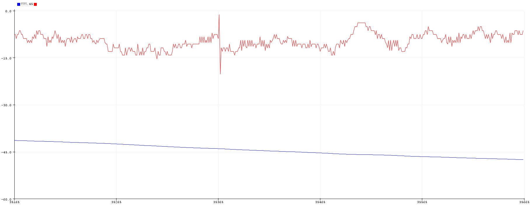
I added a few lines of code to the examples to monitor the sensor output. I’m getting clean position data from the sensor, but the velocity data is very noisy:
Velocity:RED
Position:BLUE
When i verified the design in testing before building the board, i only tested the position.. thinking that its derivation (velocity) would be clean if the position was clean..
Have you seen this before, and could this be what’s causing my jitter?
Thanks,
-Joe
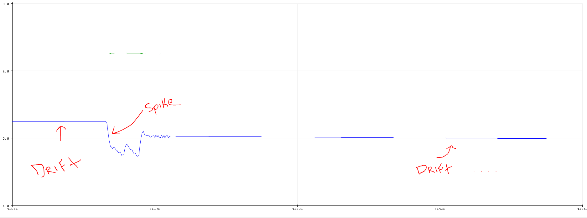
So, i found a patch… not the most efficient solution, but it works.
as a recap, i appear to have nice tuning, with the exception that once my target_setpoint is reached there is a very slow drift in the motor.voltage_q as shown below. This drift leads to an eventual spike, which causes the motor to occasionally twitch around the setpoint.
i noticed through the console, that even the smallest delta b/w the shaft_encoder and the target_setpoint ( say ~0.01 rad ) would initiate this drift.
i “fixed” the issue by adding a settle() function, which cranks down the motor.PID_velocity.I to 0 if the error b/w the target_angle and the shaft_angle is acceptable.
im not sure whats causing the underlying issue, but this will work for now
void settle(){
float delta = fabs(target_angle-motor.shaft_angle);
//Serial.println(delta);
if (delta < 0.05){
motor.PID_velocity.I = 0;//0
}
else {
motor.PID_velocity.I = 20;//0
}
}
I have another issue…lol
when i run the open loop angle control… the resistance around the setpoint is very smooth, meaning that if i move the motor manually, the resistance is spring like.
when i do the same with the closed loop angle control, there is a slight vibration for the first couple degrees.
any ideas what is causing this?
openloop angle mode, by definition, doesn’t know that you have turned the motor or by how much. It is just magnets / electromagnets trying to align. If you turn it far enough it’ll happily align to the next matching pole. It is going to feel smooth and springy.
Closed loop knows that you are moving the motor - the angle error goes through your Angle PID and cascades to you velocity PID and out pops the voltage.
I’d spend some time running in velocity mode tuning your velocity PID, once that is done angle PID is easy.
To tune velocity, start with something like a target of 10 rad/s and P=0, I=0 and increase PID.P term until speed reaches about 6 rad/s (at about 8 rad/s it’ll start to oscillate). Then increase PID.I to take up the slack. Even a small I term (e.g. 1) will take you to 10 rad/s but it might do it too slowly for your liking.
A lot of my motors have velocity PID settings of about P=0.3, I=5 and Tf of 0.1-0.001. I don’t bother with D. PID.I=20 seems very high.
In summary getting P as high as possible (but not vibrating) is better than having a high I term.
Also - you can try reducing the frequency you call move() to about once every 1ms. ESP32 are fast and calling it at 10K is going to be noisy. By sampling less often the velocity ((new angle - last angle) / 0.001s) has less noise, it works a bit like increasing Tf from 0.001 to 0.1. Note: you always want to call loopFOC as fast as possible.
Thanks Owen,
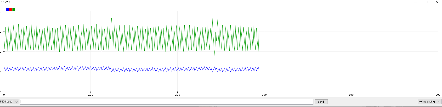
I set it to 10 rad/s, with the following settings:
P = 0.1
I = 0
D = 0
Tf = 0.005
K = 20
this is my result:
and below is with the following settings:
P = 0.1
I = 0
D = 0
Tf = 0.1
K = 20
please advise
thanks,
-joe
I can’t stress enough how this can have very good results, specially since you’re having issued with noise in velocity measurements. Put motor.move() in an if and experiment calling it every 5, 10, 15, 20 cycles and let’s see if that helps.
thanks david,
no luck so far, i’m up to 1k cycles
i cant seem to eliminate the oscillation in the velocity loop unless i set Tf >1
in other news the velocity control works really well… I’m very tempted to use the existing voltage control and close the loop around that with the AS5600.
I just want to check whether you understand what I’m suggesting, something like this where you try changing 20 to values between 5 and 200
void loop() {
   motor.loopFOC();

   static long count = 0;
   count++;
   if (count % 20 ==0) {
     motor.move(target);
     // also put Serial.print or motor.monitor() here too!
   }

}
What is your serial baud rate? 115200 is a sensible default but I sometimes go x4 this
1 Like
Hey Owen,
I appreciate the help!
yup, that looks close to mine.
Just in case, here is my main loop now:
BAUDRATE: 115200
void loop() {
motor.loopFOC();
static long count = 0;
count++;
if (count % 10 ==0) {
motor.move();
// also put Serial.print or motor.monitor() here too!
motor.monitor();
motor.command(serialReceiveUserCommand());
}
}
Here are my settings:
//---------------------------------------
motor.PID_velocity.P = 0.2;
motor.PID_velocity.I = 0;
motor.PID_velocity.D = 0;
motor.voltage_limit = 6;
motor.LPF_velocity.Tf = 0.01;
motor.P_angle.P = 20;
motor.velocity_limit = 50;
//---------------------------------------
Count = 5
Count = 10
Count = 20
I’ve jus tried with those settings on a similar motor and an as5600 i2c and got some similar shakes.
Try adjusting P down a bit and moving Tf to 0.1 (smoothing=100ms)
motor.PID_velocity.P = 0.15;
motor.PID_velocity.I = 1;
motor.PID_velocity.D = 0;
motor.voltage_limit = 6;
motor.LPF_velocity.Tf = 0.1;
motor.P_angle.P = 20;
This worked for me.
Ooh and I was using a
if (count % 100 ==0) {
I’m using 168Mhz stm which isn’t quite as fast as your esp32
thanks owen:
i changed the params to match yours, and the count
Here is my plot:
the motor goes smoothly for 45 degree, slows down to a stop, and then continues to the next radian
BTW - I tend to avoid the AS5600. They can be made to work, but they are far noisier than other 14bit magnetic sensors. If you spend £15 on a as5147 you’ll see the difference but it is 4 times more expensive! I’ve only used the SPI version of the as5147 but believe there is an i2c version (AS5048?) too. I’ve used (and like) the ma730 too.
yea i used the AS5058B originally, but switched to get the cost down
I need 12 of these drivers for my project lol
Can you send me a capture of what the velocity mode plot is supposed to look like after tuning?