Does this motor run smooth in open loop (it should do). I’m wondering if your motor is really coggy or has a bad bearing? It looks like a decent gimbal motor (probably 12n14p 10ohm) so should be perfect.
i have a t-motor with the same bolt pattern… ill give it a shot.
but the MY12-13 are really smooth. 12N14P ~10ohm
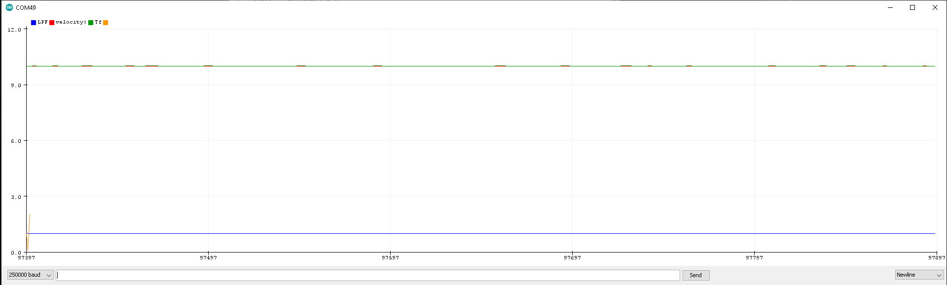
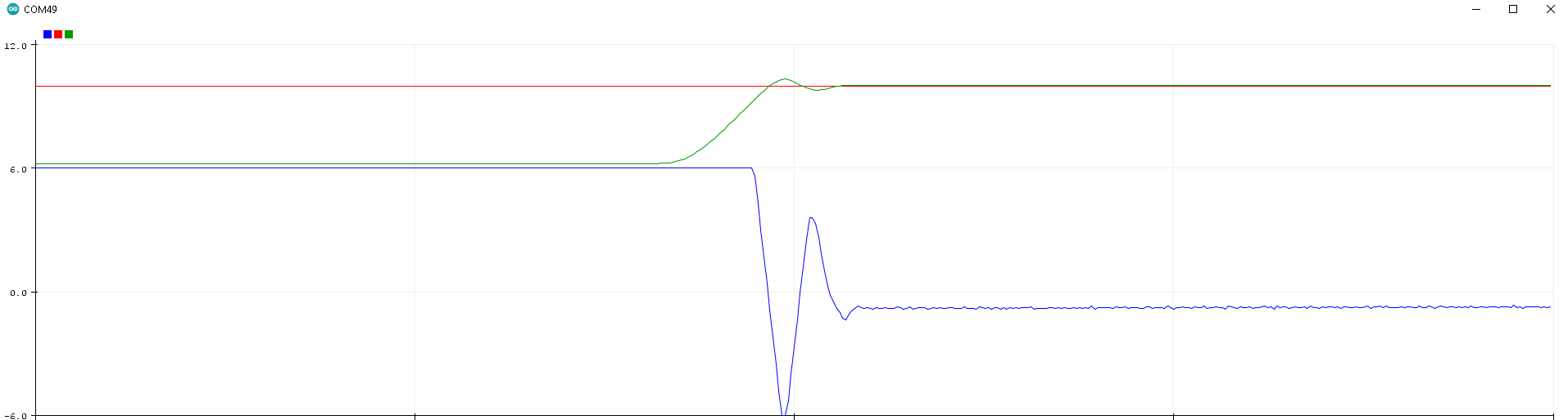
this is a plot of my position loop
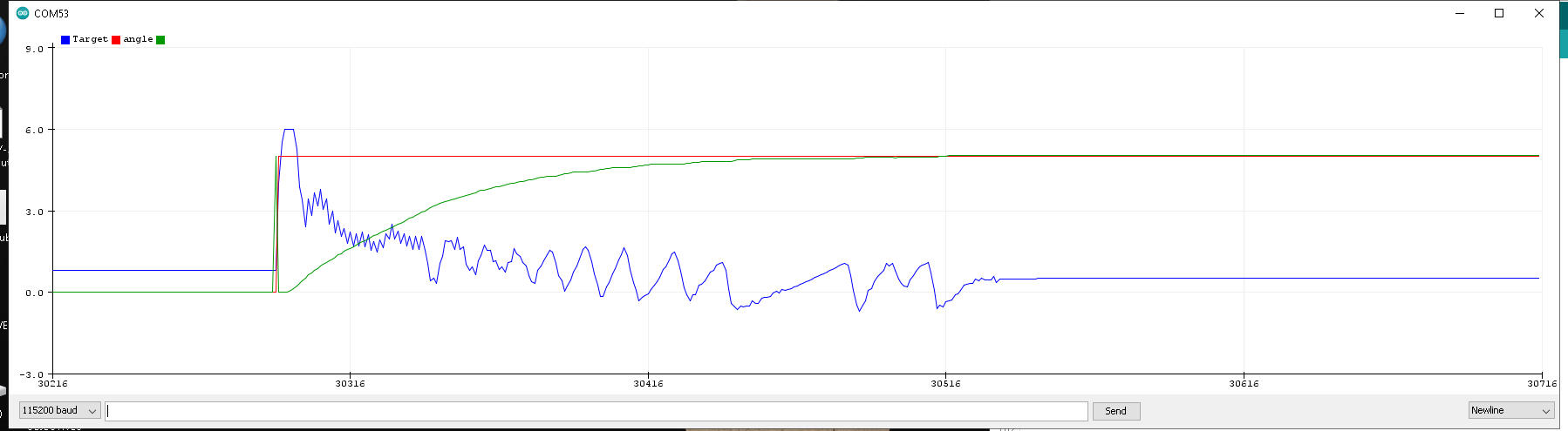
Here are a couple of captures
motor.PID_velocity.P = 0.15;
motor.PID_velocity.I = 1;
motor.PID_velocity.D = 0;
motor.voltage_limit = 6;
motor.LPF_velocity.Tf = 0.1;
motor.P_angle.P = 20;
and with your settings
motor.PID_velocity.P = 0.2;
motor.PID_velocity.I = 0;
motor.PID_velocity.D = 0;
motor.voltage_limit = 6;
motor.LPF_velocity.Tf = 0.01;
motor.P_angle.P = 20;
motor.velocity_limit = 50;
Thanks!
i can get close to that with a high Tf:
////-------------------------------------
motor.PID_velocity.P = .2;//0.2
motor.PID_velocity.I = 10;//20
motor.PID_velocity.D = 0.001;//0
motor.voltage_limit = 6;
motor.LPF_velocity.Tf = .5;//0.1
motor.P_angle.P = 20;
motor.velocity_limit = 40;//40
////-------------------------------------
but there’s still some vibration… not like the open loop velocity control
Is your looFOC running at 10,000+ samples a second (or as fast as possible!!!) and your move() at ~500-1000 samples a second?
A bunch of people have had issues with magnets that are supposed to be asymetric but are not.
My loop is running @ 1200 microseconds or ~800 hz
I just ordered this bad boy: https://www.digikey.com/en/products/detail/AS5048B-TS_EK_AB/AS5048B-AB-1.0-ND/3188613?itemSeq=355286946
Your loop is slightly slower than an arduino. That is odd. ESP32 right?
Have you tried increasing i2c clock speed? e.g. Wire.setClock(1000000);
My stm32f405 is running the loop in 500us which is also slower than I expected, but I don’t think my board can push i2c faster than 400K - some can do 3,400,000!
Hey, I can confirm that the AS5048B works well, but on ESP32 I can’t get more than 400kHz on the I2C. And even then it is a bit slower than the STM32s.
If you have a trick to up the I2C speed on ESP32 that would be cool to know!
May I ask why not use SPI if you want more sensor speed? I get much faster rates with SPI on the AS5048A…
This thread is a very interesting one to me. I think the “settle” optimisation you mention could be interesting for many use cases.
And some kind of management of the I-gain might be interesting too, as a kind of protection. Otherwise stalls can cause heat problems, I’ve burnt one motor and melted a couple of plastic magnet-holders… (in the case of the burnt motor, the “stall” was actually a stuck magnet).
Regards from Vienna,
Richard
Regarding ‘settling’ the as5600 has a 0 to 4 lsb bit configurable hysteris, to fix this. I.e it won’t report an angle change in direction unless it has changed ‘significantly’.
I’ve hardcoded a hysterisis of 1 in the hall sensor implementation without really giving much thought to it being configurable.
Perhaps hysteris should be added to all sensors in software?
The as5600 has configurable fast and slow filters for angle. As a general rule the sensor implementation just use the ‘out of the box’ settings for spi/i2c, taking a look at the datasheet and writing to config registers could improve performance for some use cases
There are many systematic approaches to this problem. And the library had very general control structure implemented two pid controller’s in cascade + filtering. Which gives you a lot of possibilities to set your system dynamics. But it also gives you two classes PIDController and LowPassFilter class and you can use them to create your own control loops.
Making a solution that works for everyone is outside the scope of the library because the code would become very very complex. We have talked about the controller classes and similar generic motion control function callbacks that you would be able to provide(or link) to the BlDCMotor or such but at the moment it is not possible.
In your case there are few things I would do in your case:
- go into the velocity loop and the velocity to 0. Is the motor behavior smooth? Are there vibrations?
The behavior should be very similar to that of holding a position. If there are some vibrations then you need to tune the PID velocity.- Start with I and D set to 0.
- And then raise I first. Be aware that in this gain type of PID controller implementation changing the P actually influences the I and D. You will see that when you rise your I gain you will need to raise a bit your P gain as well.
- In terms of D component, you can keep it very low, less than 0.005. It might help you a bit with oscillations, but derivative gain D will amplify the derivative noise of the position sensor so it will take some time to find good values.
- The filtering
Tfseems to be an important parameter for this particular sensor as well. The velocity measure is pretty noisy and you might need to raise it in the area above 0.01. The filtering introduces a time delay into the system and once the filtering constant is too high the system becomes unstable or in the particular case, you might have some osculations. Also be aware that if you introduce higher filtering values you will need to raise your proportional gainPas well.
- Once when you have a nice stable behavior for velocity loop, you can proceed to the position loop.
- Position loop has only one parameter it is the proportional gain
P. Position control does basically this:
target_velocity = P*(target_angle - current_angle);
So if your velocity loop is well tuned, then you can use the hysteresis here. And say something like this:
if(abs(target_angle - current_angle) < some value) target_velocity = 0;
else  target_velocity = P*(target_angle - current_angle);
This would be a type of dead zone feature, if there is enough people interested we might implement this feature in the PIDController class.
If you wish to do it in the Arduino loop and not implement your own control loop, then use angle mode and add this code to the Arduino loop:
if(abs(target_angle - motor.shaft_angle) < some value) P_angle.P = 0;
else P_angle.P = 20; // change the P value that you found well suited for your application
Thanks @Antun_Skuric ND @Owen_Williams @runger
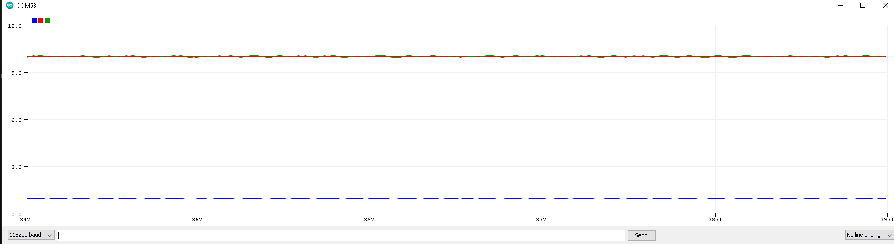
I was able to eliminate the tiny oscillation, and get pretty good motor performance with the following settings:
// //*******************************
motor.PID_velocity.P = .2;//0.2
motor.PID_velocity.I = 0;//20
motor.PID_velocity.D = 0;//0.001
motor.voltage_limit = 6;
motor.LPF_velocity.Tf = 2;//0.01
motor.P_angle.P = 40;
motor.velocity_limit = 40;//40
// //*******************************
I tried a couple different, but similar sized motors, as well as the AS048B encoder, but there wasn’t much of a change, if any.
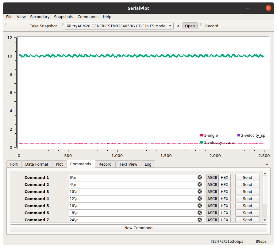
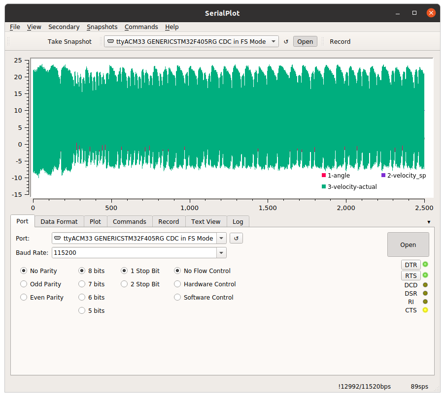
Baseline live plot: position mode
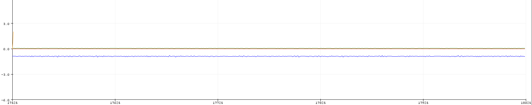
live plot velocity mode:
live plot: position mode, response to manual perturbation
This is definitely an improvement in the performance, as the twitching is eliminated, and the vibrations are significantly reduced.
I had to crank up the K( angle P controller P gain), and F(velocity Low pass filter time constant).
Its getting closer… I’m thinking the super low inertia of the rotor is making the tuning extra difficult.
I’ll try using a larger motor for comparison, and maybe spin up the simple FOC shield and arduino UNO to provide a baseline for comparison.
Let me know your thoughts.
1 Like
Owen,
This is a great questions.. im wondering this myself.
The Pico-D4 that i’m using on the custom driver board has an internal crystal that runs at 40Mhz:

Compared to the Atmega328p running on the Arduino Uno, which is running @ 20Mhz, I would expect the speed to be roughly double.
However, the same program flashed to both microcontrollers shows that the speed is the same…
I introduced a 3rd and 4th datapoint. The Sparkfun ESP32 dev, the TinyPico. Both of these run the sketch @ 500microseconds… wtf?
Anyway, while going down this path…i found out that my esp32 board manager was out of date by 1 version. So i installed the V1.0.5, and threw the mcpwm.h file back into my directory… any low and behold my vibration was completely gone! im sure what the hell happened here, but im not going down that rabbit hole right now.
this still begs the question, why isnt my pico-d4 running faster, and on top of that… how is the TinyPico - which my design is based off… running 4 times faster. I cant seem to find a Pico-D4 chip which runs at the claimed 240Mhz
whats even more perplexing.. is that when i run the folowing code on the TINYPICO, and my custom driver they both produce the same clock frequency (240Mhz). Something weird is going on here. Any ideas?
//----------------------------------------------------
#include “esp32-hal-cpu.h”
void setup() {
Serial.begin(250000);
}
void loop() {
Serial.println(ESP.getCpuFreqMHz());
delay(100);
}
//----------------------------------------------------
The oscillator frequency is typically 4-40Mhz and is not directly related to the speed of the chip. For example my custom stm32 board uses a 16MHz oscillator but runs at 168Mhz - it goes through a series of multiplies and dividers (PLL) to achieve 168Hz.
I’m not familiar with ESP32 oscillator → Sys clock frequencies but I suspect you are running at 240Mhz.
Can you try something - remove all the code apart from the i2c sensor i.e. run i2c sensor test and measure the time it takes for each sensor.getAngle() reading. If, as I suspect, the timing for one sensor.getAngle() is about 400us then your problems are a slow i2c bus.
Try calling Wire.setClock(400000) or 1000000 or 3400000 to speed up the i2c bus. Where you call this might be important. I recently found that on my stm32 calling Wire.setClock(400000) just after sensor.init() sped up my sensor.getAngle() by 4x which made a massive difference. I could drop my Tf value to 0.005 and the motor was far easier to tune.
Hey Owen,
Thanks for the feedback.
while running the “magnetic_sensor_i2c_example.ino” example per your suggestion, I tried bumping up the clock frequency to Wire.setClock(3400000), and was getting ~550us
after a few rabbit holes, I decided to try implementing the full wire function:
#define SDA 21
#define SCL 22
Wire.begin(SDA,SCL,3400000); // SDA, and SCL lines 400000
after that i was getting a pretty steady 200us
Long story short, now the “full_control_serial.ino” is running <500us.
sweeeeet ![]()
on a side note, the original full_control_serial.ino was running at 1200us, so im not sure where the other ( 1200us-500us = 700us) 700us went, but hey… thats a story for another day.
-Joe
Great news!
I reckon you’ll find it much easier to tune! And maybe you can change Tf from 2 to 0.05 (or even lower!)
I suspect esp32 defaults to i2c of 100k but also supports 400k. When you asked for 3.4M, I think you only got 400K. I get about 200us at 400k and 80us at 1M but it was a bit unstable on my setup at 1M. I think the pullups need to be lower for high speed.
That’s my experience with the ESP32 - in fact, getting more than 400K out of I2C seems to be a rare thing, not many MCUs can do it.
Awesome that it is working for you now, @digitalnomadjoe ![]() !
!
I find the all the Arduino IDEs (the original, the Pro IDE, PlatformIO in vsCode and Sloeber) have severe bugs and usability deficits that wind up costing me hours of time. ![]()