Wicket !
Imagine this on a bike handlebar. You can snap the MagTag off some neodymium magnets mounted to a rubber handlebar attachment of sorts. Without it, the motor won’t move, so it is kinda like a key. It has native USB.
E-ink sunlight test…

Wicket !
Imagine this on a bike handlebar. You can snap the MagTag off some neodymium magnets mounted to a rubber handlebar attachment of sorts. Without it, the motor won’t move, so it is kinda like a key. It has native USB.
E-ink sunlight test…
I thought on getting couple of older kindles or kobo readers, and just reverse engineering their e-ink screens. Probably you can get used one fro about 20-30 euro. This small 2.9 adafruit cost you about 35 Bucks. Though size is convienient, i can’t find a useful scenario for it in day-to-day applications as refresh rate is painfully slow. Can display maybe battery status and some less dynamic parameters.
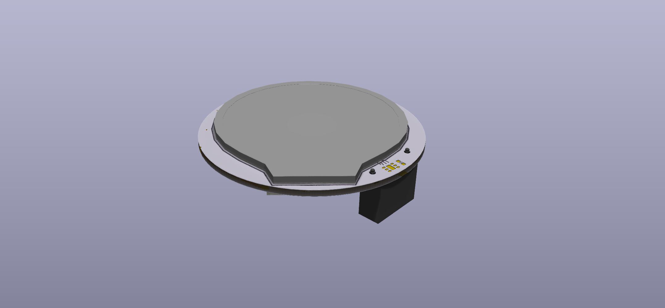
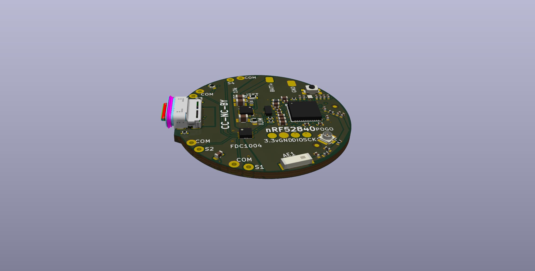
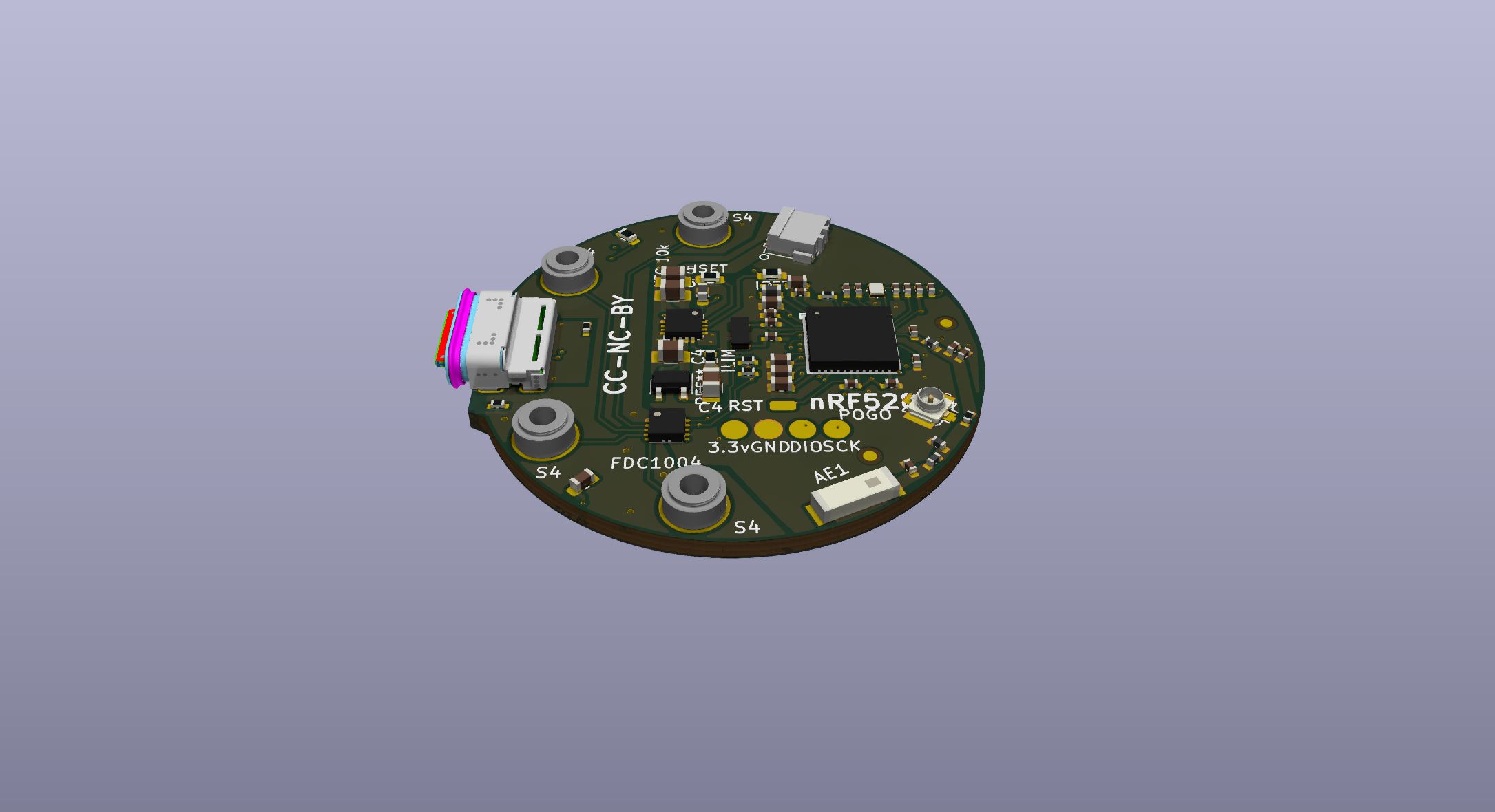
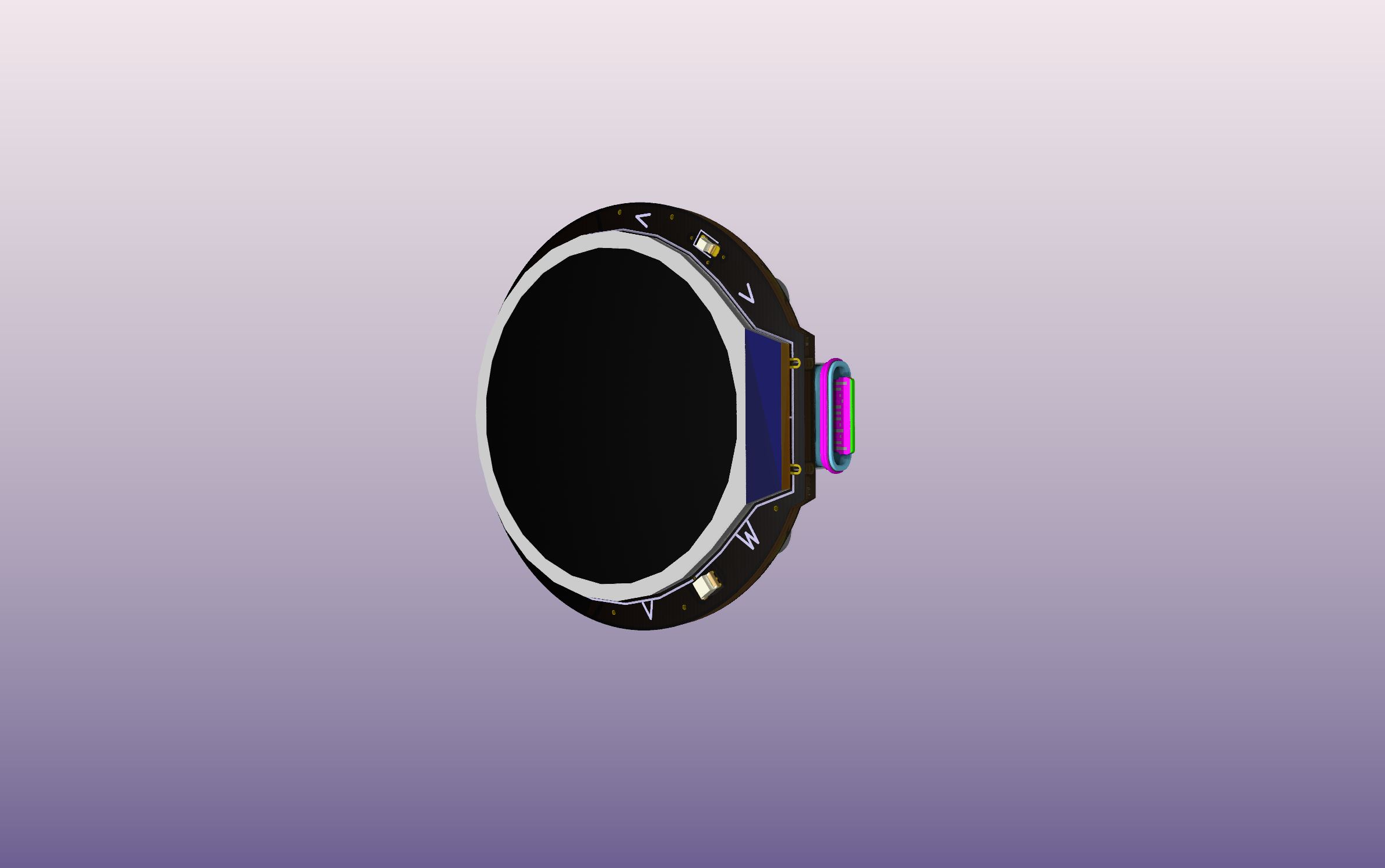
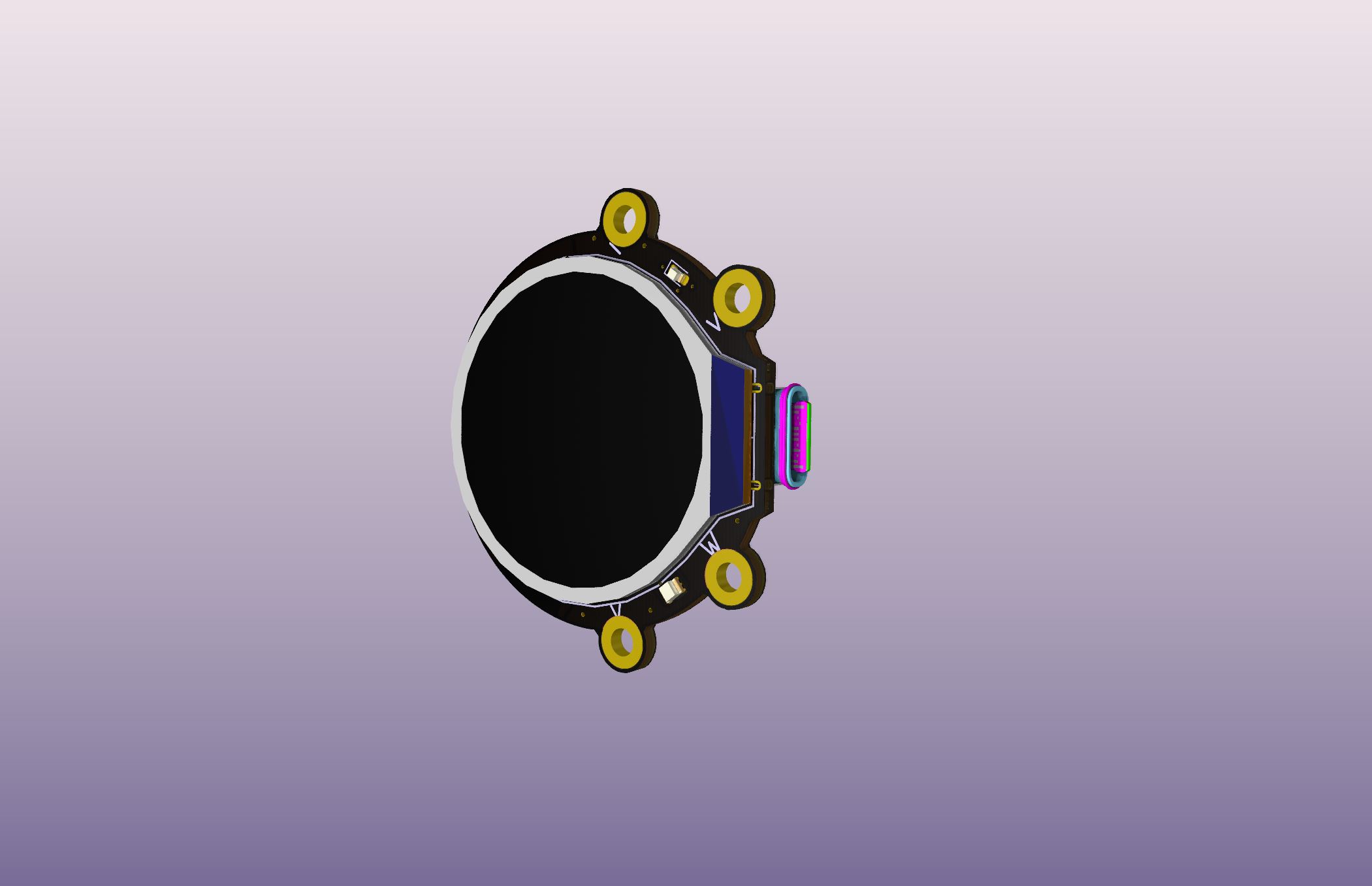
I agree, the refresh rate might be a problem. I found a 1.28inch round LCD screen which can be bought for around 6-7 $, it uses more current, but does have some power saving functions, like partial refresh. Im working on a nrf52840 solution, since it has native full speed USB and BLE. So, im wondering if it should have a battery, which will require a charging IC. With a battery, the screen can be charged next to the main battery, when charging, but should also charge, and only do so when needed, from the main battery. There are many considerations.
The screen will have 4 capacitive touch buttons, so one of them could be a wake up button to maybe turn up the backlight of the LCD. When running the screen in low power mode, i think it will consume around 20 mA. Running it full on, will consume 55ich mA.
Im thinking to do a pogo pin connection between the device and the handlebar mound, but maybe it is overkill. Maybe the vibrations from the bike will disturb the signal.
This IC measures the capacitance of 4 (button) inputs. Further it has 2 “shield” pins for buttons ground/reference. By soldering two small wires (per channel) to outside larger diameter solid wire. You can measure push button contact when human finger is close (within few mm.)
The buttons should be within one finger press distance. So, either thumb press or flipped . I suppose you get a floating value to compare in code low pass filter.
I plan on gluing one of these lense_filters into a more or les cylindrical 3D printed cabinet. One can get many different types of filters, with different properties.
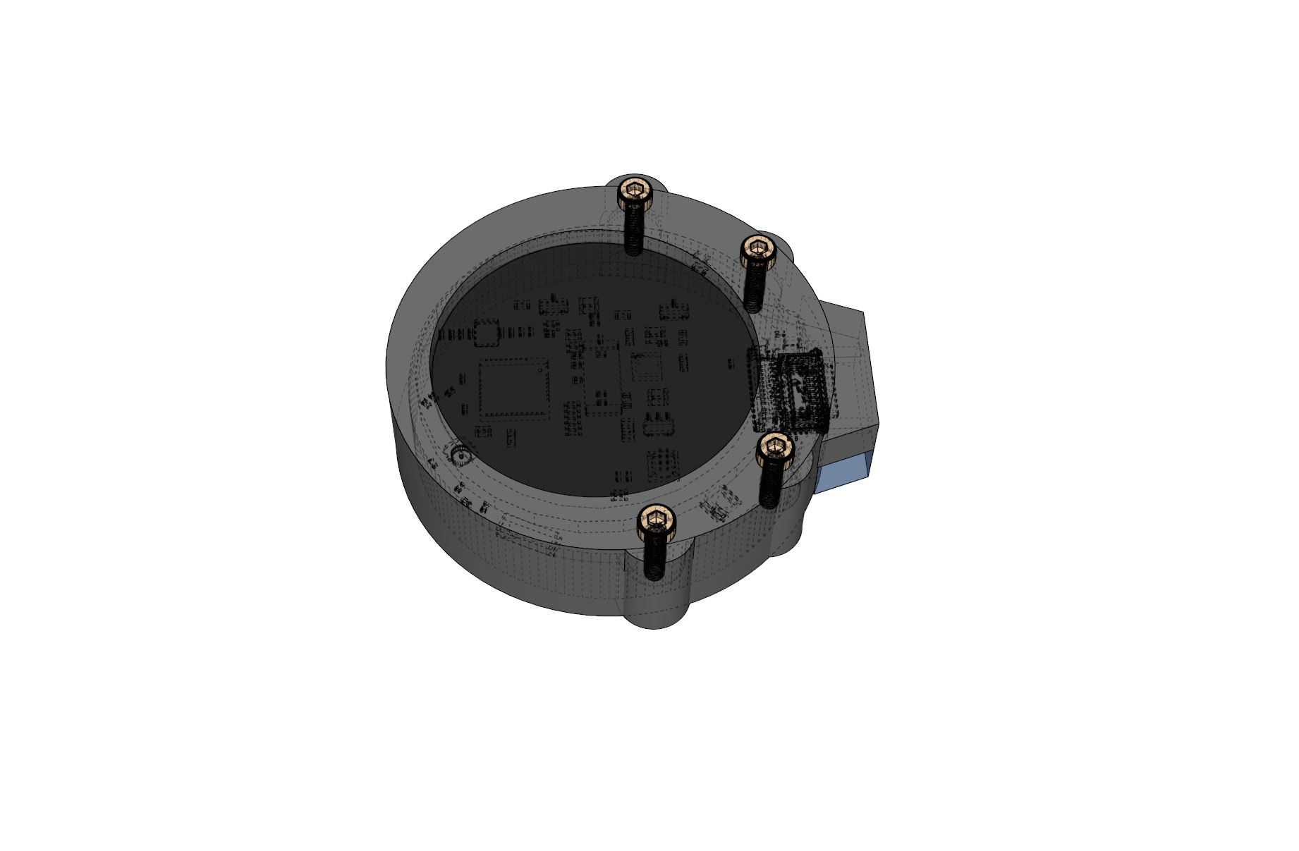
The bottom part should have strooooong neodymium magnets embedded.
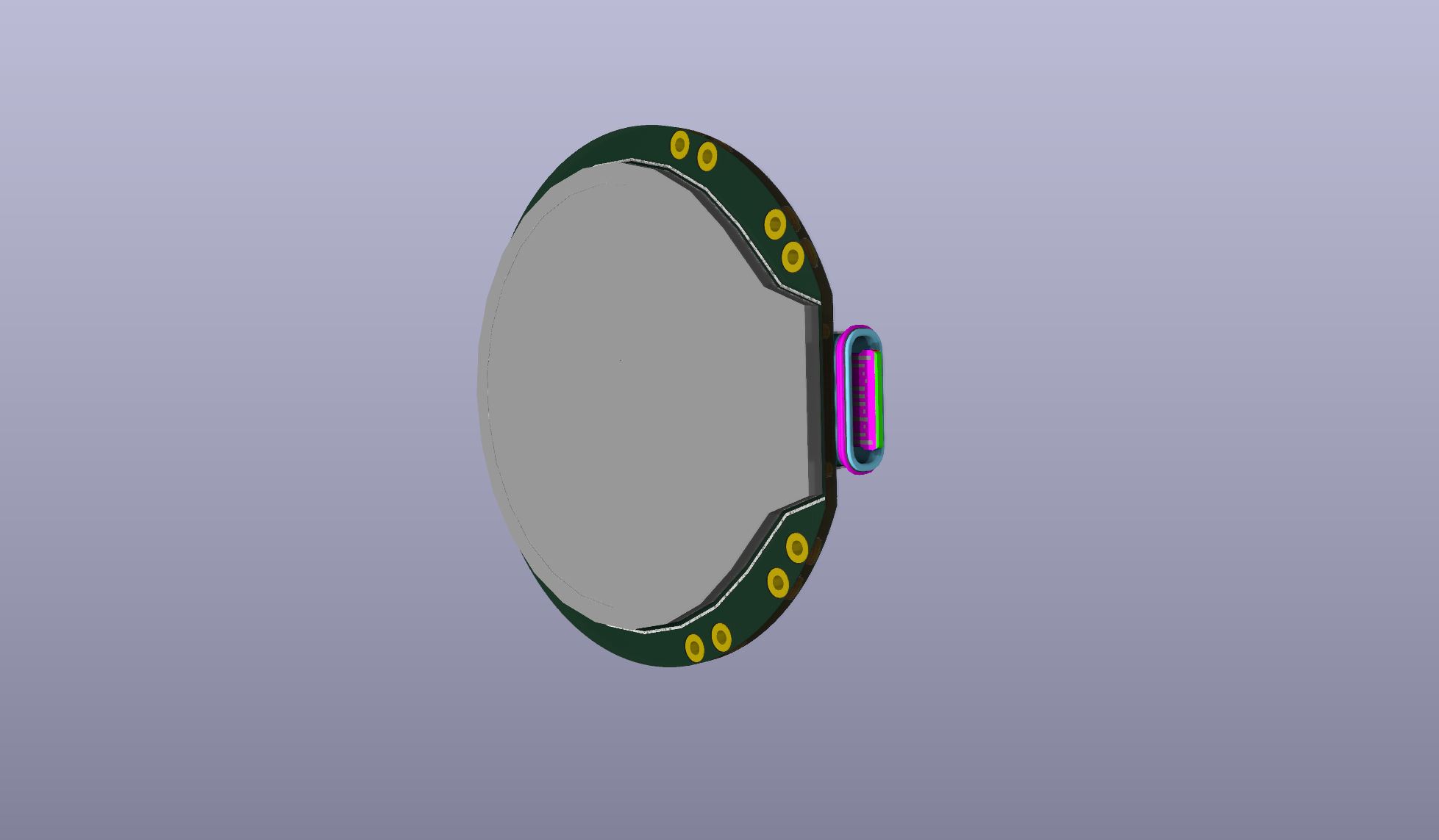
Using brass standoff (M2 thread) as capacitive button “mass”. Sensor can be programmed to offset capacitance. This will allow for fastening to battery cover, if the PCB is glued into the top part of a enclosure.
Changelog:
Added 250mA LDO fixed 3.3v for system and screen.
Added JST ADH 3 pin battery connector, with center wire as NTC 10k thermistor wire.
Changelog:
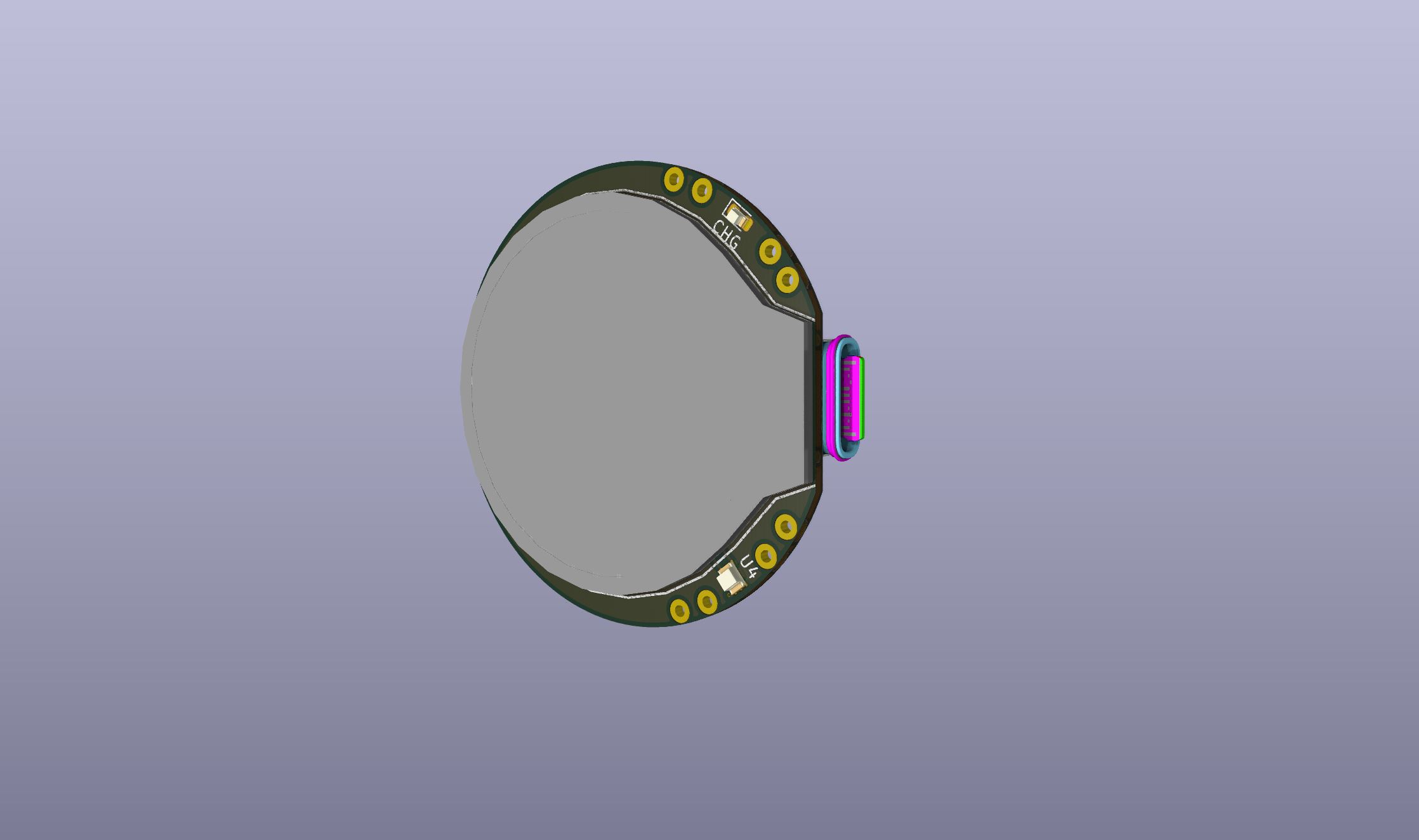
Added backlight FET to drive display backlight through a current_limiting resistor.
Besides some minor stuff, It is almost ready.
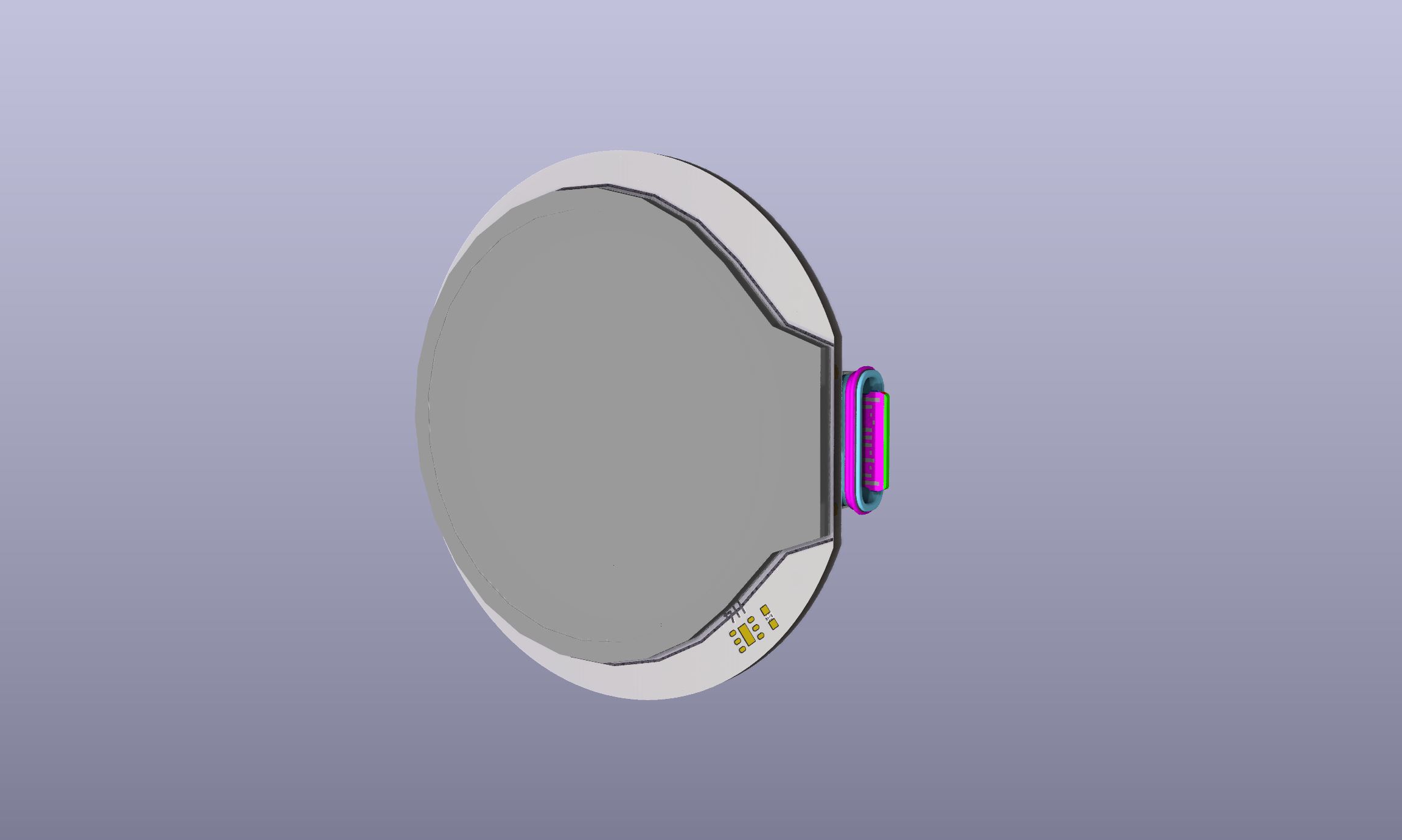
There is space for a 30mm Lipo battery (3.8v nominal) charged to 4.35v.
If connected to smartphone, it could act as a remote for shuffling music
[Edit] Considering if there should be a LED driver for front light LED. Doesn’t have to be high current. But just enough to illuminate the road ahead. Then it will become a front light with a 240x240 screen, USB full speed and BLE (Bluetooth Low Energy 5.2).
Or a small one_hand throttle for longboard
Changelog:
Deleted JST battery connector, to make room for wires if using 32650 battery.
Added SMD wire solder connections
Added FET for driving LED low_side.
NTC thermistor can either be onboard or part of the battery assembly.
Current draw while charging can either be 100mA, 500mA or set by external resistor eg. fast charge 1000mA, controlled by MCU, with pulldown resistors to GND, so initial charge will always be max. 100mA, until changed in code.
Will try to move the buttons in a bit (1.2mm). I’m thinking it is nice to be able to feel the button, even though it is capacitive buttons, when biking, and there is no more then 14mm between buttons, I would certainly like to know if the buttons was hit. Theoretically it should be possible to press the button with gloves on, depending on how thick they are.
Very neat! Im waiting for final assembly and breakdown
Will order PCB´s in a week or to. Luckily I have 6 psc nrf52840 here from a different BLE projeckt. The chip is in backorder, but should be available next year. So lots of time for prototype development.
Then there is the whole CE/FCC challenge. I do have a VNA (Vector Network Analyser), so I should be able to tune the antenna. But tuning the antenna is not enough for certification, unless the concept is classified as a development board. [Edit] (This may not be true, but just an assumption. I might be wrong here). I guess one could argue, that it is a concept in development, and that the idea is to further develop a open_source software for eBikes with this kind of waterproof HMI (Human Machine Interface), as a DIY concept, where the user will have to 3D print the enclosure and do the gluing (water tightening) and upload the code themselves.
Maybe a board is a dev. board, if it is delivered without any code on it?
I guess a development platform can be a wireless “product” PCB concept in a inclosure, but not coded, if the goal of the concept it to develop the firmware…
Hmm, does anyone know if this still holds true? If it does, i guess FCC certifications is not needed for the American marked.
There are two ways to avoid testing: restrict yourself to selling only subassemblies, or restrict yourself to devices on the exempted products list. The exempted product categories are pretty hard to remain within, and are given in section 15.103 of CFR47:
- A digital device utilized exclusively in any transportation vehicle including motor vehicles and aircraft.
[Edit] Above may not apply to wireless devices (intentional radiators)
I don’t want to be discouraging, but I think the way to do this is not make your own antennas, but to use pre-certified modules. E.g. by using an ESP32 module, which comes with FCC certification, rather than a chip, your product can get by with a declaration of conformity, much less work and realistic for an individual maker.
If you have an antenna of your own design on there (‘chip level design’), you will need to do a FCC certification including chamber testing etc… if not, I think your product will be more or less dead in the water, since regular B2B sales would be impossible, and maker and company type customers, who might be able to buy it as a ‘component’ would avoid your product in favour of one that has a certification, because they know they’d have to certify their product otherwise…