Delta has a facility just a few blocks from where I live.
It really depends on weather or not the funds dare turn down a progressive gadget meant for sustainable transportation. Maybe there is a Angel watching my back.
Let´s make it possible to change battery. This way, it becomes a pretty decent flashlight for trekking
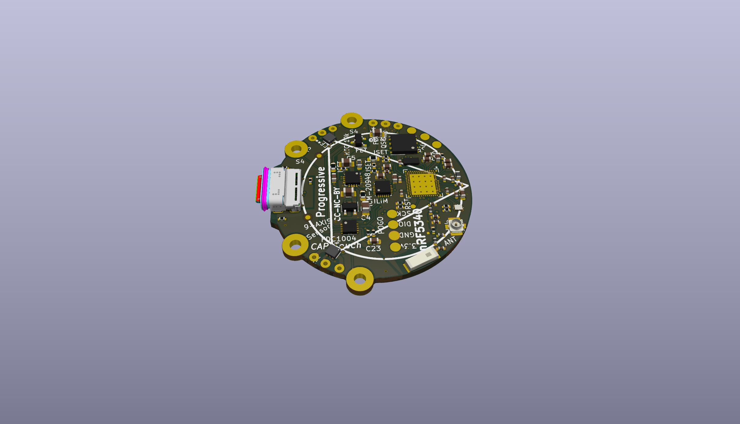
If your phone is pointing forward, the screen should be able to display a kompas, or maybe just a north dot && dirrections [Edit] With the 9-axis motion sensor, the compass is onboard.
[CHANGELOG] Added two dual mosfet´s for driving RGBW (Red, Green, Blue, White) at arround 300-500 mA each on 5x5mm Dome LED \ or 4 white LED´s for higher Lumen
Mosfet source will be connected directly to battery terminal driving LED´s using PWM, by wire.
LED pcb for opposite end will have LED´s connected to battery GND terminal.
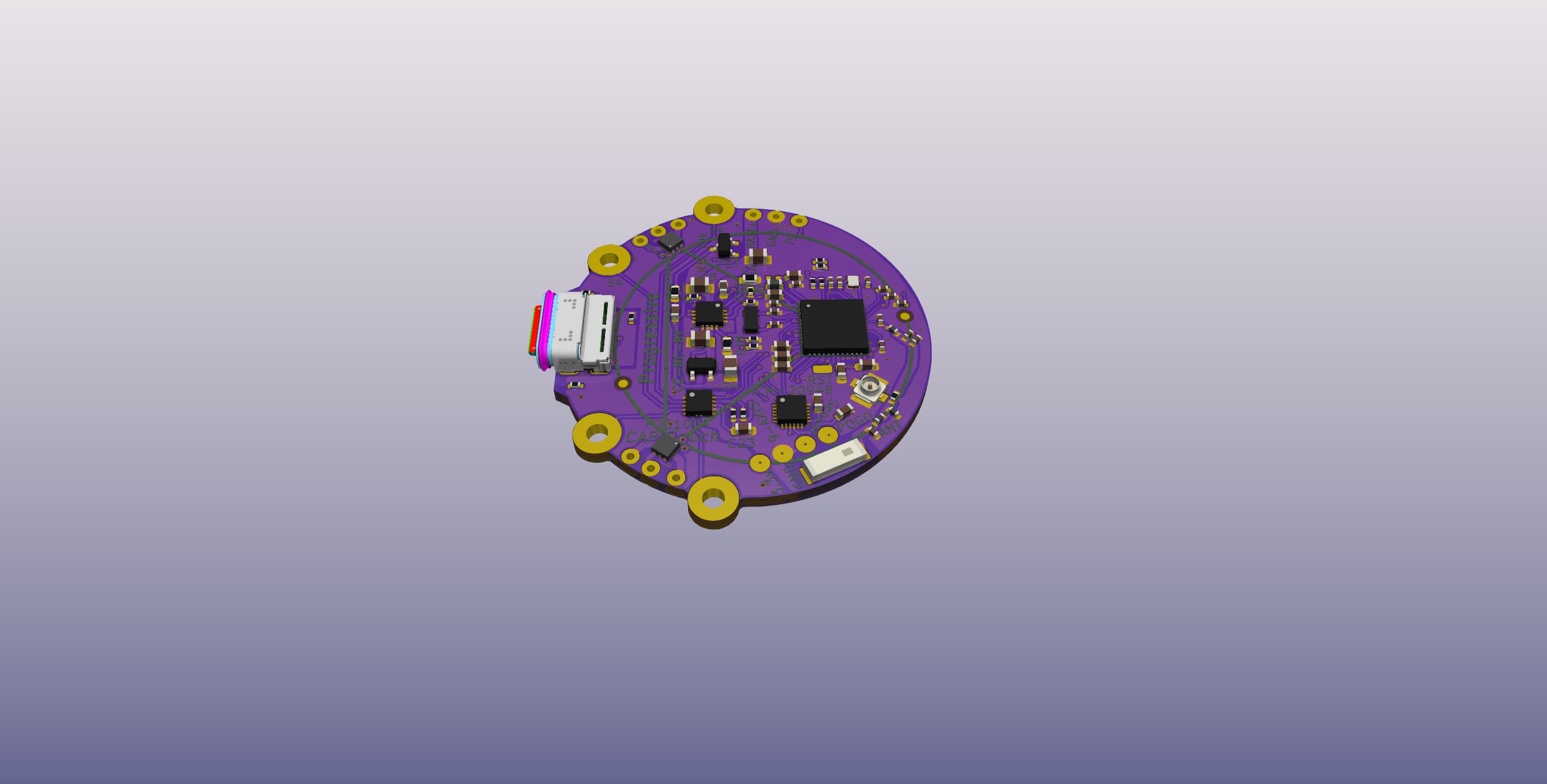
Breaking down nrf52840 passives, assigning pins. I kindof like the way nrf5340 has dedicated pins for QSPI ans Fast SPI.
Zephyr OS looks promising
In order to use QSPI pins, it is essential to do in_pad_via´s with a 0.4mm pitch. It is extremely tight space requirements.
So what is the advantage of having a 9-Axis motion sensor on a bike, connected to the motor controller as a master device. Its obvious, by knowing the acceleration, and direction / .angle movement, we know if the applied torque by the motor, has the desired effect. Its some kind of magic!
If we can find the pedal cadence in the acceleration / orientation data, then we have nailed it with regard to the bike application.
Same size, double the clock freq, and two separate cores.
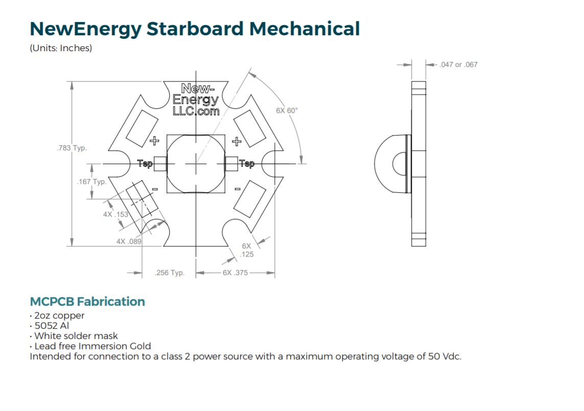
It really looks like it. How big is that board? Can I ask you how many layers is your design?
I find it a significant challenge to route all the signals to/from the MCU pins on these small boards, while still keeping to 4 or less layers and only using through hole vias… the main problem is the vias really. They’re so big compared to the pins and signal lines, there’s never space for them due to other stuff already on the board
")