I can see a few mistakes in your schematic:
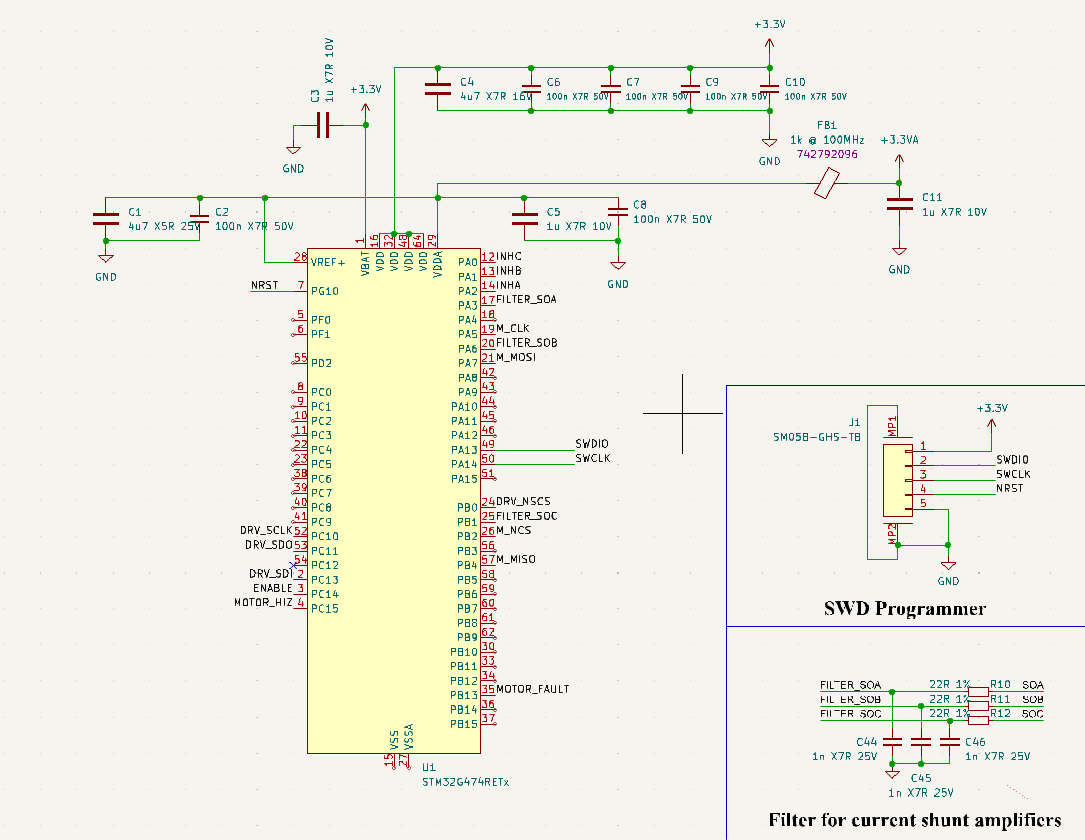
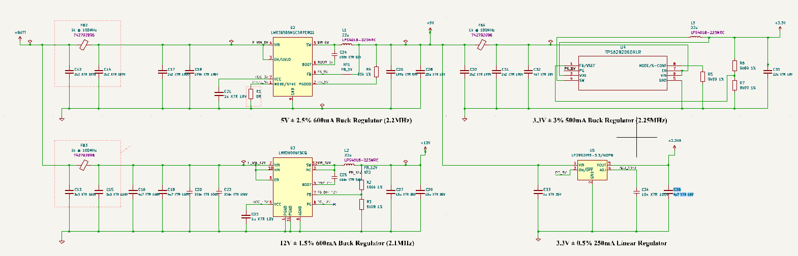
You forgot to connect the GND (VSS and VSSA) of the STM32. Your VDD is shorted to VDDA, when I think you intended for it to go through the ferrite bead. You also haven’t shown how you are generating the 3.3V for the microcontroller. I recommend using a buck converter, either buy the DRV8353RS which has it integrated or use an external one like the LMR36506. I do not recommend using the LDO as it is inefficient and will cause excessive heat generation.
You need to increase the value of your shunt resistors, with 0.2 milliohms, 40V/V amplification, and 3.3V VREF the linear current range will be (3.3-0.25)/2/40/0.0002 = 190 amps. This is way more than your MOSFETs can handle and it means the resulting signal going into the ADC will be small and your current sense accuracy will be poor. I suggest using 1 milliohm resistors, which can sense up to 38 amps.
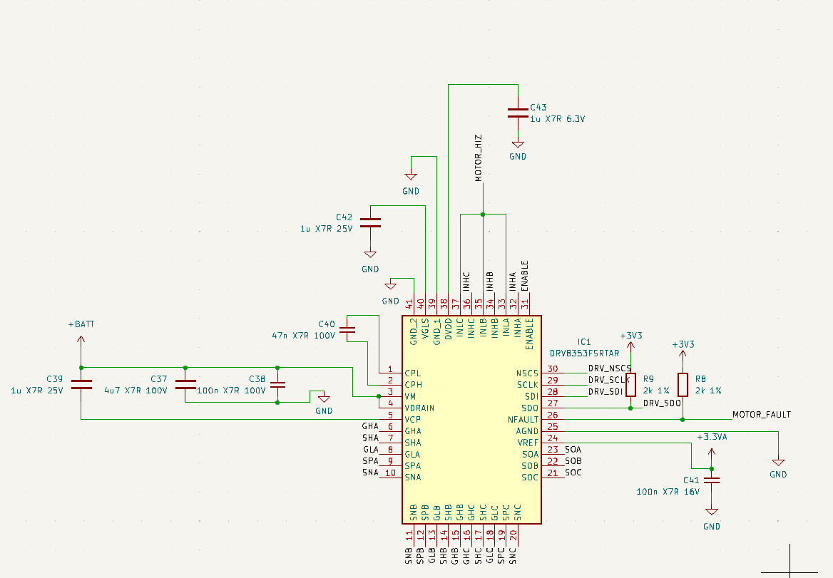
You have also mixed up the order of SNA, SPA, SNB, SPB, SNC, SPC. You need to swap the SNx with SPx. Also SLA, SLB, SLC are from another variant of the chip (DRV8350). Make sure to read the datasheet carefully, the mixing of different variants is not always obvious.
The DRV8353 series of drivers are “smart” gate drivers, and they regulate the gate current of the MOSFETs, therefore the gate resistors are unnecessary and should be removed.
It is not recommended to add a lowpass filter to the CSA output, the datasheet rates the CSA slew rate at 10V/us for a 60pF load, if you add 1nF of capacitance it might slow down the CSA and you could get inaccurate current readings. Instead I suggest removing the low pass filter and setting your ADC sampling time to 2000ns (CSA settling time to 1% with 40V/V gain), during this time the CSA will charge the internal ADC capacitor.
You also need to add more capacitance to the motor supply, I suggest at least 1000uF. Look for electrolytic or polymer capacitors with low ESR and high ripple current rating. Using multiple capacitors in parallel is OK.
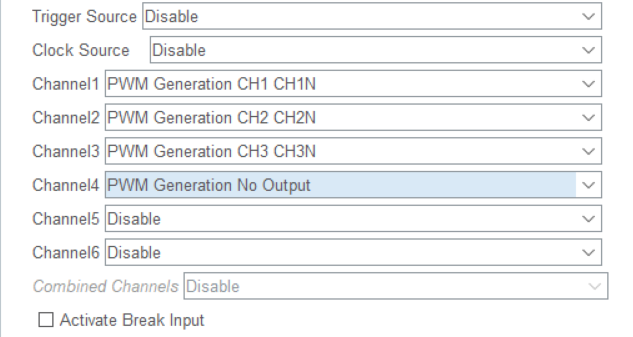
You have chosen TIM2 pins for the PWM signals, TIM2 is a general purpose 32bit timer. For motor control 32 bit timers are not necessary, with a 16 bit timer and 170MHz clock the minimum frequency is 2.6KHz. Usually motor PWM frequency is around 20-100KHz, so there is no need for a 32bit timer to achieve a lower frequency. I suggest moving the PWM pins to TIM1 or TIM8 which are advanced 16bit timers with more features than basic timers, and connecting the INL pins (to the N channels of the timer) as well. Alternatively you can use HRTIM (you chose a microcontroller with HRTIM as its main selling point), it allows complex waveform generation not possible with the other timers, but software support is not as good.
You should consider adding some communication interfaces so your motor driver can communicate with other electronics, such as exposing i2c, spi, canbus, etc. Also consider using the internal pullup resistor in the STM32 for the NFAULT pin, keep the external pullup for SDO if you want fast SPI speed.
I hope these suggestions help you improve your design.