Finally i have done routing the schematic it a kicad if anybody has some spare time please take a look at it!
https://drive.google.com/file/d/1X9b6CMt-7Kh9OIoQz-tbhgqeo1YVIbZq/view?usp=drive_link
Thank you,
kavin.
I see a problem, you have swapped TX and RX on your CAN transceiver. CAN is not like UART where you have to swap TX and RX. See page 26 of the TCAN337 datasheet for confirmation.
Also your trace widths are inconsistent. It will still work but it is not good practice, so try to keep the same trace width within the same trace.
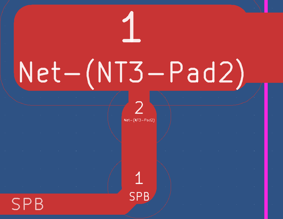
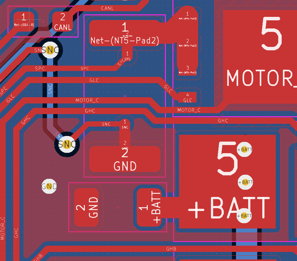
Your power traces are too thin to carry any significant current. You need to widen them by a lot, usually it is suggested to make them as wide as possible. A guideline would be at least 2mm width, and recommended 5-10mm width for the power traces. You can also use a copper pour to make your power traces if you’d prefer.
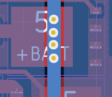
You must also consider the return current path, after the current flows out of the sense resistor and into GND it needs to return to the power supply. In your case all the current must flow through a single via, which is not enough. It is recommended to have at least 10 vias carrying the return current. Also the bottom layer return current path is quite complicated, you need to try your best to ensure a direct and mostly straight line path.
You also need to add thermal vias under the DRV8353 and under the MOSFETs if you want the best thermal performance. You should also really consider moving to a 4 layer or 6 layer PCB, the inner layers will let you have power and GND planes which help dissipate the heat better, and decrease the trace resistance. You can use an online calculator to estimate the trace resistance.
Finally you need to add at least some capacitance on your PCB, currently I only see 3x 2.2uF ceramic capacitors, which are not enough. You should aim for at least 200uF of effective capacitance, if you prefer some of it to be external that is fine but at least have 25uF effective capacitance on the PCB. Remember to check the manufacturers website for ceramic capacitor capacitance voltage derating, the effective capacitance can sometimes reduce by 95% when working at rated voltage.
Thanks a lot for looking into it As you said moving to 4 or 6 layers is the best choice but the price of the board are too high in india and i cant afford it so i tried to keep it under two layers
Noted thank you i will change those
As for the rest I’ll do it
Thanks a lot for taking your time looking into my shabby file.
Kavin.
does the drv8353 driver take care of measuring the current in the middle of the pwm signals or do we need to set it in the stm32 timer config?
The driver just has built in sense amplifiers, it does not make any usable digital signal. The synchronization with ADC to PWM has to be done on the microcontroller.
can u describe the steps that need to be done to configure that in stm32g431 or could point me to some reference manual or any articles? that would be really helpful thanks
I don’t think you need to worry about that until much later… even with misalignment it can still somewhat work.
If you want to see how the timers are synchronized with ADC, check the B-G431B-ESC1 code, there is special initialization for this board in particular already baked into simple FOC. I used that as a template when I was working on my own board.
thank you @Andrew @runger @VIPQualityPost for all the reviews you provided that i were able to complete my board and fabricate it.
I assembled the power and MCU part of the board and i was able to detect the MCU and upload program with via stlinkv2 the next step is to read the serial data from the mcu @runger told that i need to connect any one of the RX/TX pins or the uart to the stlink can anybody tell me how does that work i connected the UART3 rx tx pins to the stlink but how does the system know which UART instance i connected it to??? how does that work
In your code, you need to initialize the serial interface. You can check the STM32duino documents about how to use the alternate UART peripherals, by default it will use USART1, I think.
So I’ve configured the driver to set the registers with the appropriate values and now i want to feed the PWM signals from the simpleFOC library to the driver how do i do that?
Hi,
I used the __HAL_TIM_SET_COMPARE and it works well.
namespace fw {

namespace {

void StartTimer(TIM_HandleTypeDef* tim,
                uint16_t pin) {
  HAL_TIM_PWM_Start(tim, pin);
}
}

Stm32BldcPwm::Stm32BldcPwm(TIM_HandleTypeDef* phase_a_tim,
                           uint16_t phase_a_channel,
                           TIM_HandleTypeDef* phase_b_tim,
                           uint16_t phase_b_channel,
                           TIM_HandleTypeDef* phase_c_tim,
                           uint16_t phase_c_channel)
{
	pwm_pins_[0] = {phase_a_tim, phase_a_channel};
	pwm_pins_[1] = {phase_b_tim, phase_b_channel};
	pwm_pins_[2] = {phase_c_tim, phase_c_channel};

	StartTimer(phase_a_tim, phase_a_channel);
	StartTimer(phase_b_tim, phase_b_channel);
	StartTimer(phase_c_tim, phase_c_channel);
}

void Stm32BldcPwm::Set(float phase_a, float phase_b, float phase_c)
{
	int pwm_range = pwm_pins_[0].timer->Instance->ARR;
	__HAL_TIM_SET_COMPARE(pwm_pins_[0].timer, pwm_pins_[0].channel, phase_a * pwm_range);
	__HAL_TIM_SET_COMPARE(pwm_pins_[1].timer, pwm_pins_[1].channel, phase_b * pwm_range);
	__HAL_TIM_SET_COMPARE(pwm_pins_[2].timer, pwm_pins_[2].channel, phase_c * pwm_range);
}

Stm32BldcPwm::~Stm32BldcPwm() {}

}
void BLDCDriver3PWM::setPwm(float Ua, float Ub, float Uc) {

  // limit the voltage in driver
  Ua = _constrain(Ua, 0.0f, voltage_limit);
  Ub = _constrain(Ub, 0.0f, voltage_limit);
  Uc = _constrain(Uc, 0.0f, voltage_limit);
  // calculate duty cycle
  // limited in [0,1]
  dc_a = _constrain(Ua / voltage_power_supply, 0.0f , 1.0f );
  dc_b = _constrain(Ub / voltage_power_supply, 0.0f , 1.0f );
  dc_c = _constrain(Uc / voltage_power_supply, 0.0f , 1.0f );


  bldc_pwm_.Set(dc_a, dc_b, dc_c);
}
do you know how to setup this in platformio?
Make STM32 project with current settings, this is for genericSTM32F405RG, so just change to your specific MCU.
[env:genericSTM32F405RG]
platform = ststm32
board = stm32f4stamp
board_build.mcu = stm32f405rgt6
board_build.core = stm32
board_build.f_cpu = 168000000L
upload_protocol = stlink
framework = arduino
lib_deps =
stm32duino/STM32duino FreeRTOS@^10.3.2
askuric/Simple FOC@^2.3.3
lib_archive = false
monitor_speed = 9600
build_type = debug
debug_tool = stlink
debug_build_flags = -O0 -ggdb3 -g3
build_flags = -w
-DHAL_CAN_MODULE_ENABLED
-DENABLE_HWSERIAL3
-DPIN_SERIAL3_RX=PB11
-DPIN_SERIAL3_TX=PB10
-D PIO_FRAMEWORK_ARDUINO_ENABLE_CDC
-D HAL_SDRAM_MODULE_ENABLED
-D HAL_MDMA_MODULE_ENABLED
-D HAL_DMA_MODULE_ENABLED
-D INSTRUCTION_CACHE_ENABLE
Then just use standard simplefoc code to test driver pwm like
BLDCDriver3PWM driver = BLDCDriver3PWM(MOTOR_INH_A, MOTOR_INH_B, MOTOR_INH_C, EN_GATE);

driver.pwm_frequency = 20000;
driver.voltage_power_supply = 12;
driver.voltage_limit = 12;
driver.init();

loop:
driver.setPwm(3,6,5);
will this work ???
#include <SPI.h>
#include <SimpleFOC.h>

// BLDC driver instance
BLDCDriver6PWM driver = BLDCDriver6PWM(PA8,PC13,PA9,PB0,PA10,PB1);

#define SELECT PB10
#define MOTOR_ENABLE PB11
#define MOTOR_FAULT PB12

SPIClass SPI_2(PB15, PB14, PB13);

void printBinary(uint16_t value)
{
  for (int i = 15; i >= 0; i--)
  {
    Serial.print((value >> i) & 1);
  }
  Serial.println();
}

void readRegister(uint16_t addr)
{
  SPI_2.beginTransaction(SPISettings(1000000, MSBFIRST, SPI_MODE1));
  digitalWrite(SELECT, LOW);
  // Read address 0x03
  uint16_t response = SPI_2.transfer16(addr);
  // take the SS pin high to de-select the chip:
  SPI_2.endTransaction();
  digitalWrite(SELECT, HIGH);
  delayMicroseconds(1);
  printBinary(response); // Print the binary response
}

void writeRegister(uint16_t addr)
{
  SPI_2.beginTransaction(SPISettings(125000, MSBFIRST, SPI_MODE1));
  digitalWrite(SELECT, LOW);
  SPI_2.transfer16(addr);
  digitalWrite(SELECT, HIGH);
  delayMicroseconds(1);
  SPI_2.endTransaction();
}

void setup()
{
  Serial.begin(9600);
  pinMode(SELECT, OUTPUT);
  pinMode(MOTOR_ENABLE, OUTPUT);
  pinMode(MOTOR_FAULT, INPUT_PULLUP);
  digitalWrite(MOTOR_ENABLE, HIGH);
  digitalWrite(SELECT, HIGH);
  SPI_2.begin();
  delay(1000);
  Serial.print("Reading Registers before Settings values:");
  Serial.println();
  // Set address 0x02h to (PWM_MODE = 01b, OCP_ACT = 1b, Others to Default)
  writeRegister(0b0001010000000000);
  // Set address 0x03h to (All values are set to Default)
  writeRegister(0b0001101100000000);
  // Set address 0x04h to (TDRIVE = 00b Others to Default)
  writeRegister(0b0010010000000000);
  // Set address 0x05h to (DEAD_TIME = 00b, OCP_MODE =00b, OCP_DEG=00b VDS_LVL=0000b)
  writeRegister(0b0010100000000000);
  // Set address 0x06h to (CSA_GAIN = 11b, Others to default)
  writeRegister(0b0011001011000011);
  // Set address 0x07h to (All values are set to Default)
  writeRegister(0b0011100000000000);

  // driver config
  // power supply voltage [V]
  driver.voltage_power_supply = 12;
  driver.init();
  // link the motor and the driver
  motor.linkDriver(&driver);

  // limiting motor movements
  // motor.phase_resistance = 3.52 // [Ohm]
  // motor.current_limit = 2;   // [Amps] - if phase resistance defined
  motor.voltage_limit = 1;   // [V] - if phase resistance not defined
  motor.velocity_limit = 5; // [rad/s] cca 50rpm

  // open loop control config
  motor.controller = MotionControlType::velocity_openloop;

  // init motor hardware
  motor.init();

  Serial.begin(115200);
  Serial.println("Motor ready!");
  Serial.println("Set target velocity [rad/s]");
  _delay(1000);
}

void loop()
{
  // open loop velocity movement
  // using motor.voltage_limit and motor.velocity_limit
  motor.move();
}
You do not set any target velocity, try motor.move(1);
How do you find the motor voltage and motor current so that i don’t burn anything??
For starters, just set the motor voltage limit low enough that the current can’t get too high (Ohm’s law).
After that you can try the voltage-based current limiting. But it’s only an approximation, so keep the voltage limit low until you have the PIDs tuned. When the motor is oscillating from poorly tuned PID, the real current can be significantly higher than intended.