DRV8323S Breakout Board Attempt 2 (Requests for comment)

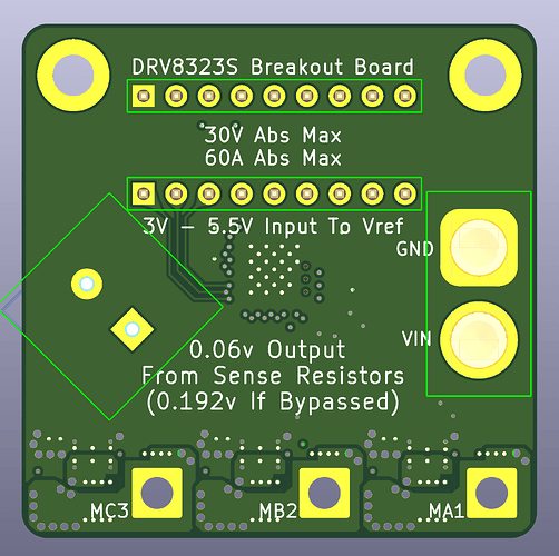
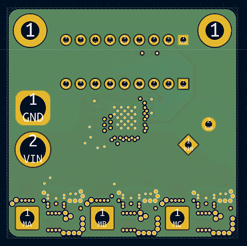
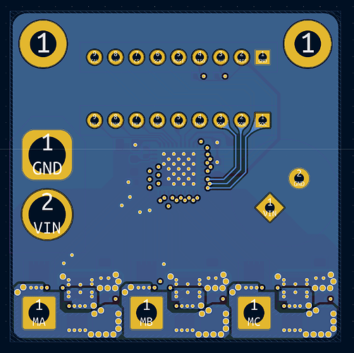
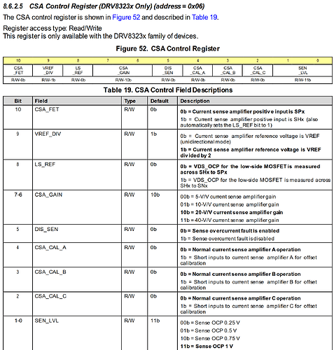
Continuation of this thread but hopefully the right format this time. I’ve tried to implement all the suggestions I received.

Quick rundown:

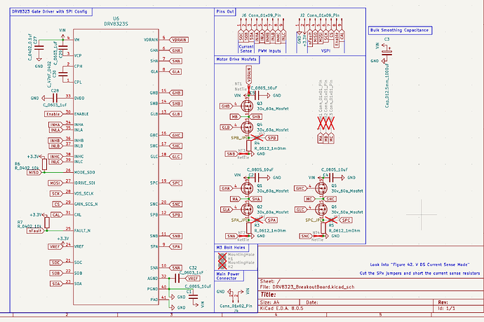
  • DRV8323S configured with low side sensing

  • Still 40mmx40mm despite numerous warnings (This totally wont come back to bite me)

  • 30v, 60a (Package limited) mosfets.

  • A whole 1000uF on board capacitance (Way too low. More will be added on the connector as needed)

  • 3 10uF ceramic caps next to the Fets (They’ll be trying their best)

  • XT60 Input connector

  • 2.54mm headers compatible with a breadboard

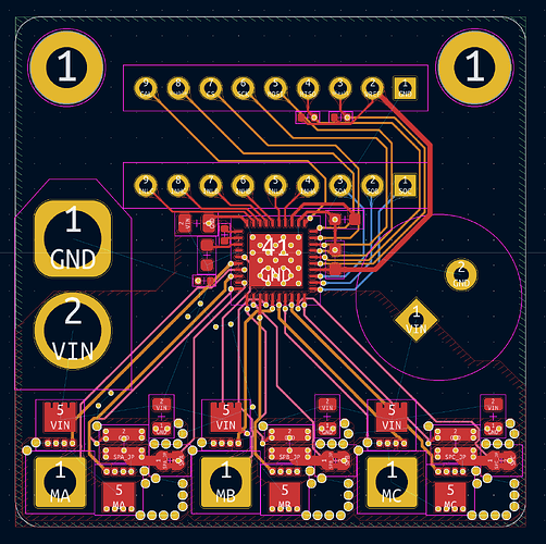
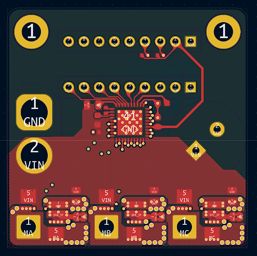
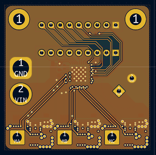
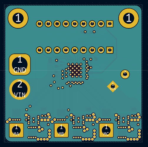
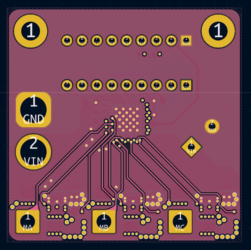
It also now a 6 layer board.

  • Power Polygons + Input PWM
  • GND Plane
  • GND Fill + Gate Wires and SPI Wires
  • VCC
  • GND Fill + Analog sensor wires for DRV8323S
  • GND Fill + Analog current Out

Not Quite the stackup suggested by jmyk but its as close as I personally could get with a 6 layer board.

For capacitor sizing I’ve contacted an EE budy of mine to help with the SPICE sim. He doesn’t do circuit stuff but he still remembers SPICE from college and will help walk me through it sometime next week.

I also have one of those cheap multi-meter/oscilloscope things on its way that can hopefully help measure the input ripple.

I’ll probably place the order for this batch Sunday afternoon.

Its also 2:20 AM where I am so I’ll be heading to bed after I update the github.


I have regrets.


I’m buying a stencil next time.

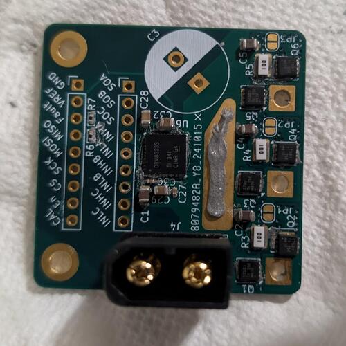
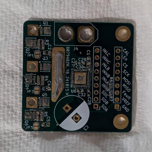
Pasting by hand didn’t work until I mixed my paste with flux. Even then, it was incredibly sloppy.

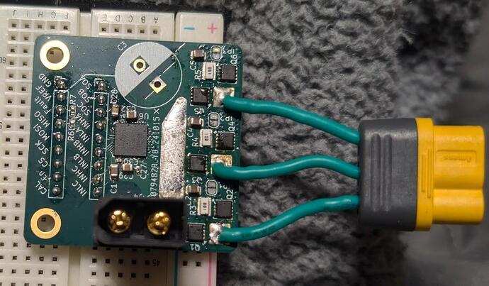
I was going to mount the back of the board to a large heatsink. Unfortunately my brain didn’t account for the xt60 blocking the 2.54mm headers and subsequent breadboard. Next board is getting that connector on extension wires. Additionally, the heatsinks I planned to use on the MOSFETs blocked the motor wires.

I’m probably going to try the board tomorrow. I’ll start with simple tests just to make sure all my solder joints are good. Then I’ll try it with simple foc.

No bulk capacitance for now. I want to see how bad the voltage ripple is and add caps from there.

1 Like

What you do is really awesome. You’ll wake up tomorrow and be like, yeah, let’s do it again.

No regrets.

Cheers,
Valentine

1 Like

Yeah, stencils are great, but then you also need a stencil printer or self-made setup to keep it in place and then lift it up…

I can’t really see that from the picture? It looks like there is space for the headers? Is it sticking too far down? Headers are easily available in longer lengths so I think you can still solder headers to the bottom and stick it in a breadboard?

Yeah putting heat sinks in there looks hairy, maybe if you soldered the phase wires on from underneath?

1 Like

Does excessive amounts of tape work?

I was going to but a solderable breadboard on top. I’d need to extend a significant ways to plug in the xt60.

I wanted the bottom of the board to be entirely affixed to a large heatsink.

I’ll have figure something out. I’m thinking of making my own. For now I guess I find the limit with no cooling.

That’s nice to hear.

I am extremely confused as to why I cannot seem to get good readings via SPI.

I’ve checked wires, read documentation, stared at it intensely but can’t find the problem.

Here is my mapping of what I believe the possible combinations for reading registers should be.

20:20:42.093 -> Sent: 1000000000000000 (Decimal: 32768)	, Received: 0000000000000000 (Decimal: 0)
20:20:42.157 -> Sent: 1000100000000000 (Decimal: 34816)	, Received: 0000000000000000 (Decimal: 0)
20:20:42.189 -> Sent: 1001000000000000 (Decimal: 36864)	, Received: 0000000000000000 (Decimal: 0)
20:20:42.253 -> Sent: 1001100000000000 (Decimal: 38912)	, Received: 0000000000000000 (Decimal: 0)
20:20:42.285 -> Sent: 1010000000000000 (Decimal: 40960)	, Received: 0000000000000000 (Decimal: 0)
20:20:42.350 -> Sent: 1010100000000000 (Decimal: 43008)	, Received: 0000000000000000 (Decimal: 0)
20:20:42.382 -> Sent: 1011000000000000 (Decimal: 45056)	, Received: 0000000000000000 (Decimal: 0)
20:20:42.446 -> Sent: 1011100000000000 (Decimal: 47104)	, Received: 0000000000000000 (Decimal: 0)
20:20:42.478 -> Sent: 1100000000000000 (Decimal: 49152)	, Received: 0000000000000000 (Decimal: 0)
20:20:42.542 -> Sent: 1100100000000000 (Decimal: 51200)	, Received: 0000000000000000 (Decimal: 0)
20:20:42.607 -> Sent: 1101000000000000 (Decimal: 53248)	, Received: 0000000000000000 (Decimal: 0)
20:20:42.639 -> Sent: 1101100000000000 (Decimal: 55296)	, Received: 0000000000000000 (Decimal: 0)
20:20:42.704 -> Sent: 1110000000000000 (Decimal: 57344)	, Received: 0000000000000000 (Decimal: 0)
20:20:42.737 -> Sent: 1110100000000000 (Decimal: 59392)	, Received: 0000000000000000 (Decimal: 0)
20:20:42.801 -> Sent: 1111000000000000 (Decimal: 61440)	, Received: 0000000000000000 (Decimal: 0)
20:20:42.833 -> Sent: 1111100000000000 (Decimal: 63488)	, Received: 0000000000000000 (Decimal: 0)
20:20:42.897 -> Sent: 0000000000000001 (Decimal: 1)	, Received: 0000000000000000 (Decimal: 0)
20:20:42.929 -> Sent: 0000000000010001 (Decimal: 17)	, Received: 0000000000000000 (Decimal: 0)
20:20:42.994 -> Sent: 0000000000001001 (Decimal: 9)	, Received: 0000000000000000 (Decimal: 0)
20:20:43.026 -> Sent: 0000000000011001 (Decimal: 25)	, Received: 0000000000000011 (Decimal: 3)
20:20:43.091 -> Sent: 0000000000000101 (Decimal: 5)	, Received: 0000000000000000 (Decimal: 0)
20:20:43.155 -> Sent: 0000000000010101 (Decimal: 21)	, Received: 0000000000000000 (Decimal: 0)
20:20:43.187 -> Sent: 0000000000001101 (Decimal: 13)	, Received: 0000000000000000 (Decimal: 0)
20:20:43.252 -> Sent: 0000000000011101 (Decimal: 29)	, Received: 0000000000000011 (Decimal: 3)
20:20:43.284 -> Sent: 0000000000000011 (Decimal: 3)	, Received: 0000000000000000 (Decimal: 0)
20:20:43.348 -> Sent: 0000000000010011 (Decimal: 19)	, Received: 0000000000000000 (Decimal: 0)
20:20:43.380 -> Sent: 0000000000001011 (Decimal: 11)	, Received: 0000000000000000 (Decimal: 0)
20:20:43.445 -> Sent: 0000000000011011 (Decimal: 27)	, Received: 0000000000000011 (Decimal: 3)
20:20:43.477 -> Sent: 0000000000000111 (Decimal: 7)	, Received: 0000000000000000 (Decimal: 0)
20:20:43.542 -> Sent: 0000000000010111 (Decimal: 23)	, Received: 0000000000000000 (Decimal: 0)
20:20:43.606 -> Sent: 0000000000001111 (Decimal: 15)	, Received: 0000000000000000 (Decimal: 0)
20:20:43.639 -> Sent: 0000000000011111 (Decimal: 31)	, Received: 0000000000000011 (Decimal: 3)
20:20:43.704 -> Finished0000000 (Decimal: 43008)	, Received: 0000000000000000 (Decimal: 0)

I’m sure its probably something with my code.

//#include <DRV8323S.h>

const int chipSelectPin = 4; // Change this to your CS pin
const int enableDRV8323Pin = 17;

void setup() {
  // Start the Serial communication
  Serial.begin(115200);
  
  // Initialize SPI
  SPI.begin();
  
  // Set the chip select pin as output
  pinMode(chipSelectPin, OUTPUT);
  digitalWrite(chipSelectPin, HIGH); // Deselect the device

  //Enable the DRV8323
  pinMode(enableDRV8323Pin, OUTPUT);
  digitalWrite(enableDRV8323Pin, HIGH);

  delay(1000);
}

uint16_t valueList[] = {
  0b1000000000000000, 
  0b1000100000000000,
  0b1001000000000000,
  0b1001100000000000,
  0b1010000000000000,
  0b1010100000000000,
  0b1011000000000000,
  0b1011100000000000, 
  0b1100000000000000,
  0b1100100000000000,
  0b1101000000000000,
  0b1101100000000000,
  0b1110000000000000,
  0b1110100000000000,
  0b1111000000000000,
  0b1111100000000000,
  0b0000000000000001,
  0b0000000000010001,
  0b0000000000001001,
  0b0000000000011001,
  0b0000000000000101,
  0b0000000000010101,
  0b0000000000001101,
  0b0000000000011101,
  0b0000000000000011,
  0b0000000000010011,
  0b0000000000001011,
  0b0000000000011011,
  0b0000000000000111,
  0b0000000000010111,
  0b0000000000001111,
  0b0000000000011111,
};

uint16_t idx = 0;

void loop() {
  if(idx>=32){
    Serial.println("Finished");
    // Disable the DRV8323
    digitalWrite(enableDRV8323Pin, LOW);
    delay(1000000000000);
  };
  //Serial.println(0x8000 | (regAdr & 0x7) << 11);
  // Select the SPI device
  digitalWrite(chipSelectPin, LOW);

  // Begin SPI transaction with specified settings
  SPI.beginTransaction(SPISettings(1000000, MSBFIRST, SPI_MODE1));

  // Write to the SPI device
  uint16_t response = SPI.transfer(valueList[idx]);
  
  // Deselect the device
  digitalWrite(chipSelectPin, HIGH);
  
  // Print the response to the Serial Monitor
  Serial.print("Sent: ");
  Serial.print(printBinary(valueList[idx], 16)); // Print in binary
  Serial.print(" (Decimal: ");
  Serial.print(valueList[idx]);
  Serial.print(")\t, Received: ");
  Serial.print(printBinary(response, 16)); // Print response in binary
  Serial.print(" (Decimal: ");
  Serial.print(response);
  Serial.println(")");

  // End the transaction
  SPI.endTransaction();
  
  // Prevent another loop
  delay(50);
  idx++;
}

String printBinary(int num, int bits) {
  String binaryString = "";
  
  // Loop through each bit
  for (int i = bits - 1; i >= 0; i--) {
    // Check if the bit at position i is set
    if (num & (1 << i)) {
      binaryString += "1";
    } else {
      binaryString += "0";
    }
  }
  
  return binaryString;
}```


If I don't power the DRV8323 with an exernal power supply and just have vref connected, I get 255 as a response.

Any ideas?
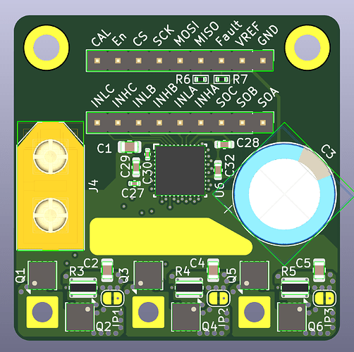
This is the table for the defaults for register 0x06

Both ways return zero when I try to read.

Attempting to write and then read yields 3 despite me not writing 3 to the registry,

Also, don’t grab the tip of a 330 °C soldering iron with your bare fingers.
I may have done this more than once despite having used soldering irons for more than six years…

1 Like

I used the DRV8353FS SPI they are not very different though. Here’s my SPI code for setting the registers

void writeRegister(uint16_t addr)
{
  SPI_2.beginTransaction(SPISettings(1000000, MSBFIRST, SPI_MODE1));
  digitalWrite(SELECT, LOW);
  SPI_2.transfer16(addr);
  digitalWrite(SELECT, HIGH);
  delayMicroseconds(1);
  SPI_2.endTransaction();
}

void DRV8353_init()
{
  pinMode(SELECT, OUTPUT);
  pinMode(MOTOR_ENABLE, OUTPUT);
  pinMode(MOTOR_FAULT, INPUT_PULLUP);
  digitalWrite(MOTOR_ENABLE, HIGH);
  digitalWrite(SELECT, HIGH);
  SPI_2.begin();
  delayMicroseconds(100);
  // Set address 0x02h to (PWM_MODE = 01b, OCP_ACT = 1b, Others to Default)
  writeRegister(0b0001010000000000);
  // Set address 0x03h to (All values are set to Default)
  writeRegister(0b0001101100110011);
  // Set address 0x04h to (TDRIVE = 00b Others to Default)
  writeRegister(0b0010010000000000);
  // Set address 0x05h to (DEAD_TIME = 00b, OCP_MODE =00b, OCP_DEG=00b VDS_LVL=0000b)
  writeRegister(0b0010100000100000);
  // Set address 0x06h to (CSA_GAIN = 11b, Others to default)
  writeRegister(0b0011001011000011);
  // Set address 0x07h to (All values are set to Default)
  writeRegister(0b0011100000000000);
}

Hope it helps

2 Likes

This is incredibly helpful.
Thank you for sharing.

I’m now thinking its a problem with my wiring. I’ll figure this out eventually.

This ONE LINE is the entire reason mine wasn’t working.
It would only ever send 8 bits of data because I used transfer instead of transfer16.

This is my new output. Still doesn’t seem to match the defaults of the datasheet but I have actual data now

21:47:55.293 -> Sent: 1000100000000000 (Decimal: 34816)	, Received: 0000000000000000 (Decimal: 0)
21:47:55.358 -> Sent: 1001000000000000 (Decimal: 36864)	, Received: 0000011111111111 (Decimal: 2047)
21:47:55.389 -> Sent: 1001100000000000 (Decimal: 38912)	, Received: 0000001010000011 (Decimal: 643)
21:47:55.455 -> Sent: 1010000000000000 (Decimal: 40960)	, Received: 0000001010000000 (Decimal: 640)
21:47:55.488 -> Sent: 1010100000000000 (Decimal: 43008)	, Received: 0000000000000000 (Decimal: 0)
21:47:55.553 -> Sent: 1011000000000000 (Decimal: 45056)	, Received: 0000000000000000 (Decimal: 0)
21:47:55.616 -> Sent: 1011100000000000 (Decimal: 47104)	, Received: 0000000010100000 (Decimal: 160)
21:47:55.648 -> Sent: 1100000000000000 (Decimal: 49152)	, Received: 0000000000000000 (Decimal: 0)
21:47:55.713 -> Sent: 1100100000000000 (Decimal: 51200)	, Received: 0000000000000000 (Decimal: 0)
21:47:55.745 -> Sent: 1101000000000000 (Decimal: 53248)	, Received: 0000000000000000 (Decimal: 0)
21:47:55.810 -> Sent: 1101100000000000 (Decimal: 55296)	, Received: 0000000000000000 (Decimal: 0)
21:47:55.843 -> Sent: 1110000000000000 (Decimal: 57344)	, Received: 0000001010000000 (Decimal: 640)
21:47:55.906 -> Sent: 1110100000000000 (Decimal: 59392)	, Received: 0000000000000000 (Decimal: 0)
21:47:55.938 -> Sent: 1111000000000000 (Decimal: 61440)	, Received: 0000000000000000 (Decimal: 0)
21:47:56.003 -> Sent: 1111100000000000 (Decimal: 63488)	, Received: 0000000010100000 (Decimal: 160)```

I had changed the SPI mode to zero at some point. I set it back to one and everything seems to work correctly now.

//#include <DRV8323S.h>

const int chipSelectPin = 4; // Change this to your CS pin
const int enableDRV8323Pin = 17;

void setup() {
  // Start the Serial communication
  Serial.begin(115200);
  
  // Initialize SPI
  SPI.begin();
  
  // Set the chip select pin as output
  pinMode(chipSelectPin, OUTPUT);
  digitalWrite(chipSelectPin, HIGH); // Deselect the device

  //Enable the DRV8323
  pinMode(enableDRV8323Pin, OUTPUT);
  digitalWrite(enableDRV8323Pin, HIGH);

  delay(1000);
}
uint16_t valueList[] = {
  0b1000000000000000, 
  0b1000100000000000,
  0b1001000000000000,
  0b1001100000000000,
  0b1010000000000000,
  0b1010100000000000,
  0b1011000000000000,
  0b1011100000000000, 
  0b1100000000000000,
  0b1100100000000000,
  0b1101000000000000,
  0b1101100000000000,
  0b1110000000000000,
  0b1110100000000000,
  0b1111000000000000,
  0b1111100000000000,
};
uint16_t idx = 0;

void loop() {
  if(idx>=16){
    Serial.println("Finished");
    // Disable the DRV8323
    digitalWrite(enableDRV8323Pin, LOW);
    delay(1000000000000);
  };
  //Serial.println(0x8000 | (regAdr & 0x7) << 11);
  // Select the SPI device
  digitalWrite(chipSelectPin, LOW);

  // Begin SPI transaction with specified settings
  SPI.beginTransaction(SPISettings(1000000, MSBFIRST, SPI_MODE1));

  // Write to the SPI device
  uint16_t response = SPI.transfer16(valueList[idx]);
  
  // Deselect the device
  digitalWrite(chipSelectPin, HIGH);
  
  // Print the response to the Serial Monitor
  Serial.print("Sent: ");
  Serial.print(printBinary(valueList[idx], 16)); // Print in binary
  Serial.print(" (Decimal: ");
  Serial.print(valueList[idx]);
  Serial.print(")\t, Received: ");
  Serial.print(printBinary(response, 16)); // Print response in binary
  Serial.print(" (Decimal: ");
  Serial.print(response);
  Serial.println(")");

  // End the transaction
  SPI.endTransaction();
  
  // Prevent another loop
  delay(50);
  idx++;
}

String printBinary(int num, int bits) {
  String binaryString = "";
  
  // Loop through each bit
  for (int i = bits - 1; i >= 0; i--) {
    // Check if the bit at position i is set
    if (num & (1 << i)) {
      binaryString += "1";
    } else {
      binaryString += "0";
    }
  }
  
  return binaryString;
}
22:13:52.218 -> Sent: 1000100000000000 (Decimal: 34816)	, Received: 0000000000000000 (Decimal: 0)
22:13:52.284 -> Sent: 1001000000000000 (Decimal: 36864)	, Received: 0000000000000000 (Decimal: 0)
22:13:52.316 -> Sent: 1001100000000000 (Decimal: 38912)	, Received: 0000001111111111 (Decimal: 1023)
22:13:52.380 -> Sent: 1010000000000000 (Decimal: 40960)	, Received: 0000011111111111 (Decimal: 2047)
22:13:52.412 -> Sent: 1010100000000000 (Decimal: 43008)	, Received: 0000000101011001 (Decimal: 345)
22:13:52.476 -> Sent: 1011000000000000 (Decimal: 45056)	, Received: 0000001010000011 (Decimal: 643)
22:13:52.508 -> Sent: 1011100000000000 (Decimal: 47104)	, Received: 0000000000000000 (Decimal: 0)
22:13:52.573 -> Sent: 1100000000000000 (Decimal: 49152)	, Received: 0000001010000000 (Decimal: 640)
22:13:52.637 -> Sent: 1100100000000000 (Decimal: 51200)	, Received: 0000000000000000 (Decimal: 0)
22:13:52.670 -> Sent: 1101000000000000 (Decimal: 53248)	, Received: 0000000000000000 (Decimal: 0)
22:13:52.733 -> Sent: 1101100000000000 (Decimal: 55296)	, Received: 0000000000000000 (Decimal: 0)
22:13:52.764 -> Sent: 1110000000000000 (Decimal: 57344)	, Received: 0000000000000000 (Decimal: 0)
22:13:52.829 -> Sent: 1110100000000000 (Decimal: 59392)	, Received: 0000000100000001 (Decimal: 257)
22:13:52.861 -> Sent: 1111000000000000 (Decimal: 61440)	, Received: 0000000010100000 (Decimal: 160)
22:13:52.925 -> Sent: 1111100000000000 (Decimal: 63488)	, Received: 0000011100000000 (Decimal: 1792)
22:13:52.989 -> Finished
1 Like

So I’ve gotten a motor to spin.

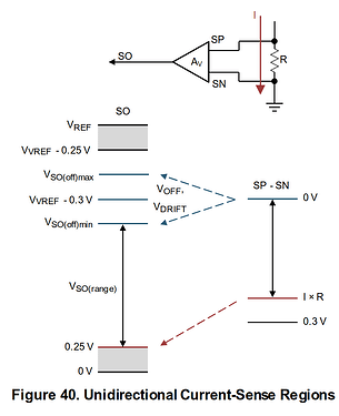
Probing the signals with my cheap oscilloscope seems to indicate that the Current sense signals are inverted.
Checking the datasheet also seems like this is the case.

Does SimpleFOC just handle this as is for Low Side current sensing or do I need to modify some code?

Everything else seems good so far with the exception of voltage ripple.

Just set a negative value for gain in the LowsideCurrentSense constructor.

1 Like

That is far simpler than I expected but it makes perfect sense.
Thank you.

With no cooling, things get uncomfortable warm to the touch at around 15 amps and zero speed. At about 20 amps, the motor will cut out if no movement occurs. I’m thinking the back negative trace is over heating and tripping the thermal cutout on the DRV8323.

The voltage ripple has appeared to range between 300 and 500mV. I assume that’s pretty bad.

Edit: I added heatsinks. Nothing gets warm now but it still disables randomly.

Edit 2: Its an under voltage lockout and I need to charge my battery

Edit 3: It’s looking like 20 amps is the max without a custom heatsink on the fets directly. I’ll know more when I try to blow a board up though.