That sounds about right. Comparing to stats on NeuMotors, I would guesstimate you’ll get around 7Nm continuous torque at 80W dissipation, and 14Nm peak torque with 320W unsustainable heating.
You may be right. In that case I will have to increase the gear ratio. Unless it’s enough. What I wish to achieve is not being taken over by old ladies on the hills and to avoid breaking a huge sweat when commuting.
Yes, I agree. It is somewhat out of the ordinary concept to perceive UGS as having perceptions. Imagine if UGS could orient itself in the machine defined space. In theory it would then know where the blip happened, and could therefore redo the path with a more conservative cut ( if talking CNC).
Never underestimate a droid

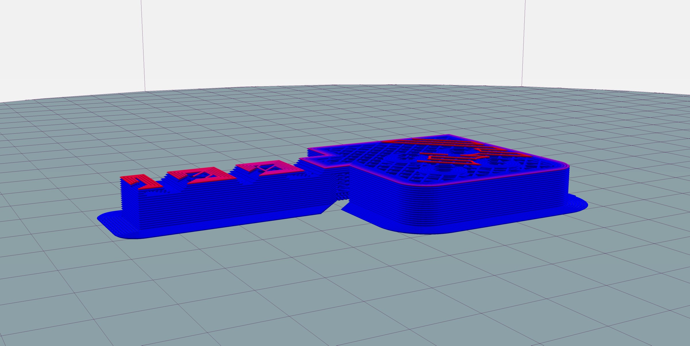
@dekutree64 Took your advice on utilizing the maximum work_area.
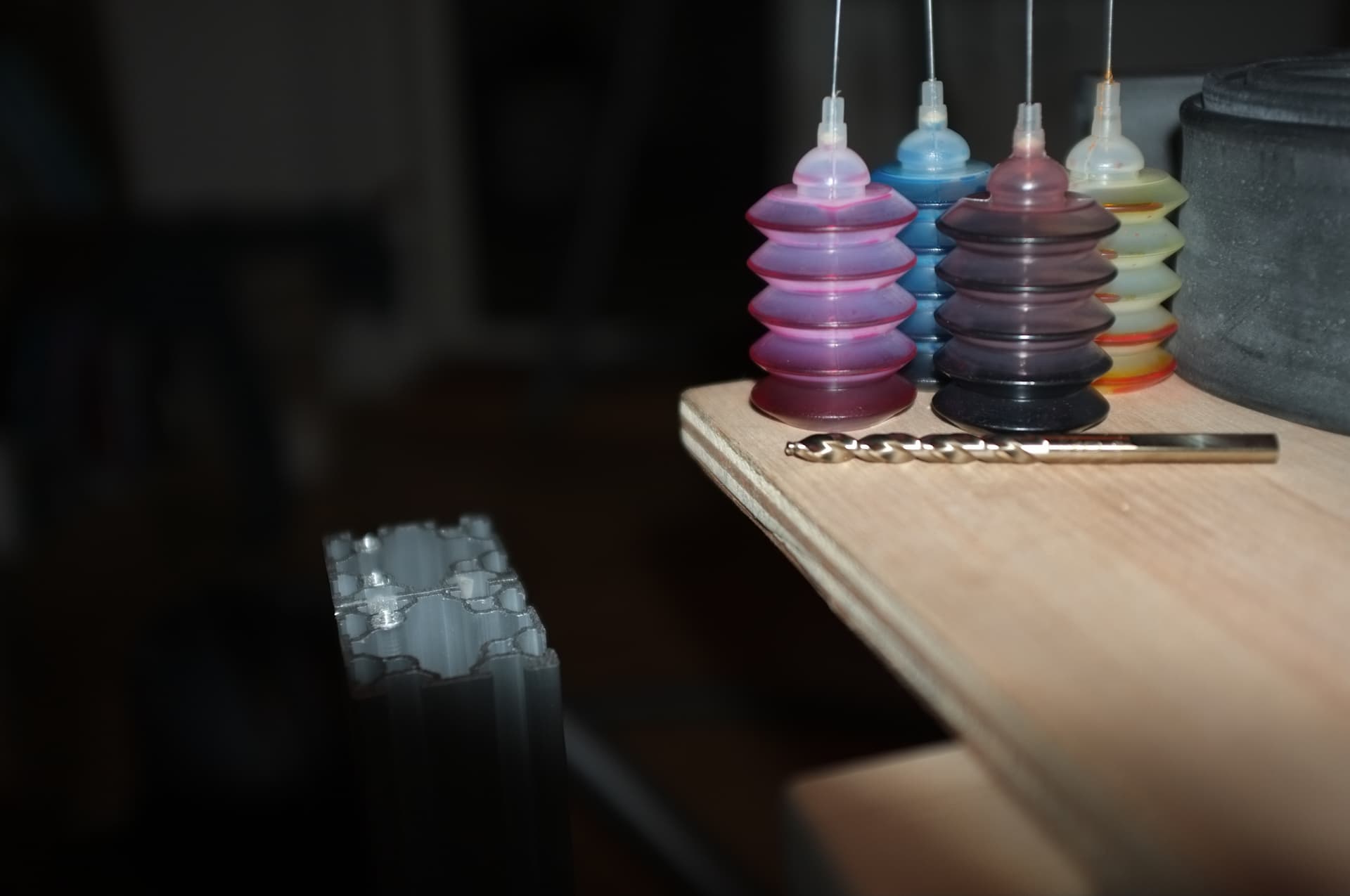
Lessons learned. Do not rely on printed stencil for drilling. Use caliper when possible and take the time to mark/score the surface with the caliper before punching the drill_mark. Drilling the holes on a machine is another matter, but if doing it by hand, then a combination of caliper lines and printed stencil could work, so you know exactly where to line up the stencil.
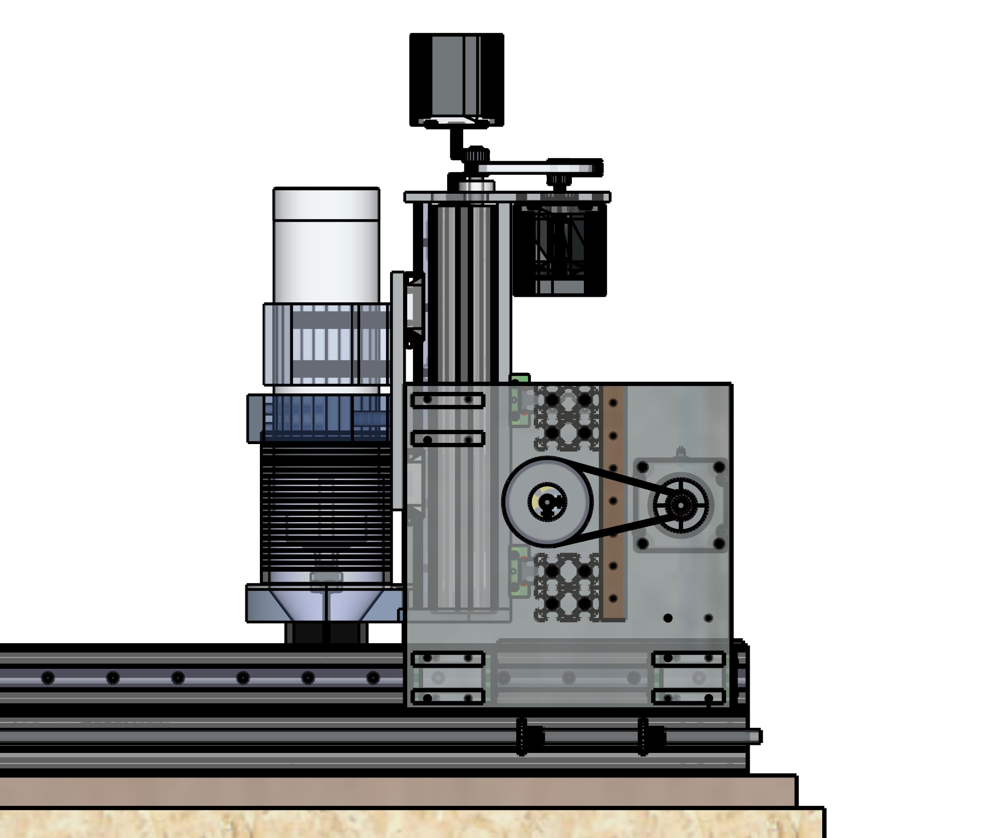
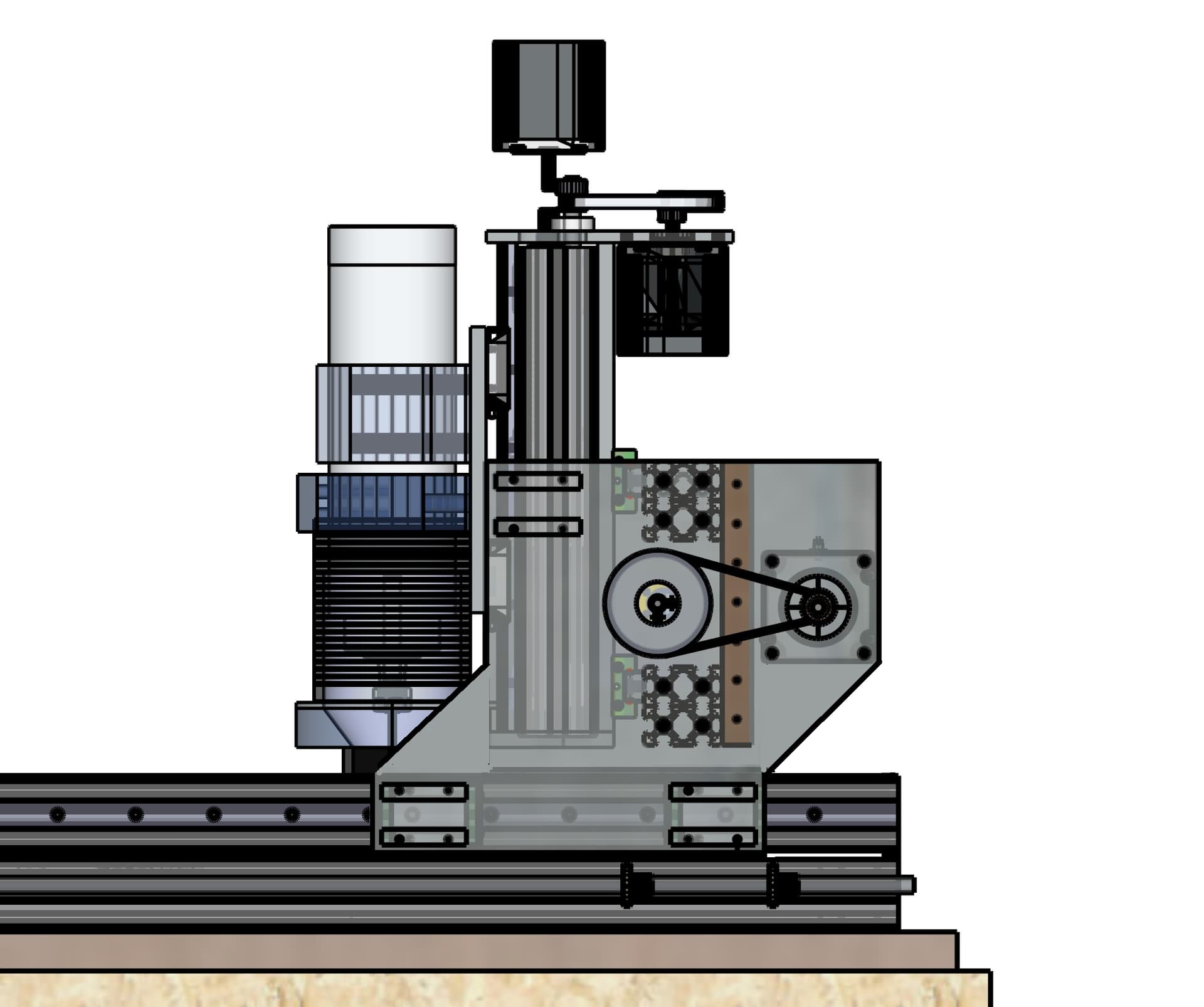
Some CNC design use a C-Beam, which will give a center-to-center distance of 60mm from the two X rails. By using 2x 4040 beams, like shown, the center-to-center distance is 105mm. This may not seem like much, but the added distance between the rails, will make the machine more rugged. The general idea behind this → design is compact and robust.
Looks like you lost an equal amount of Y range, though… you could shift the Y blocks forward to reclaim that lost range, but the X motor needs to go up on top or it would hang off the back and increase the necessary enclosure size. It looks like the Z motor would only need to be slightly higher to avoid colliding with the X motor. Or perhaps the Z motor could be moved around to the side.
And yes, manually drilling all the holes is a challenge ![]() I usually end up needing a lot of tiresome work with a needle file to correct the hole locations due to drill wandering. Use a step drill to keep larger holes centered. But usually the position will already be a little bit off by the time I get to the 3mm tip size.
I usually end up needing a lot of tiresome work with a needle file to correct the hole locations due to drill wandering. Use a step drill to keep larger holes centered. But usually the position will already be a little bit off by the time I get to the 3mm tip size.
Since it looks like you’ve already started fabrication of your current side plate design, you might as well get up and running with that. Afterward you could use the machine to make new side plates with the X motor up top, and all the holes drill perfectly.
Yeah, I could get some more Y range, by moving the X motor, but I deliberately but it there, on the inside, to avoid collision with the wire_belt and vac_hose. Since its “Just” one rail on the Y, I prefer having the block´s as far apart as possible.
Edit: Wait a bit. Right, I see your point.
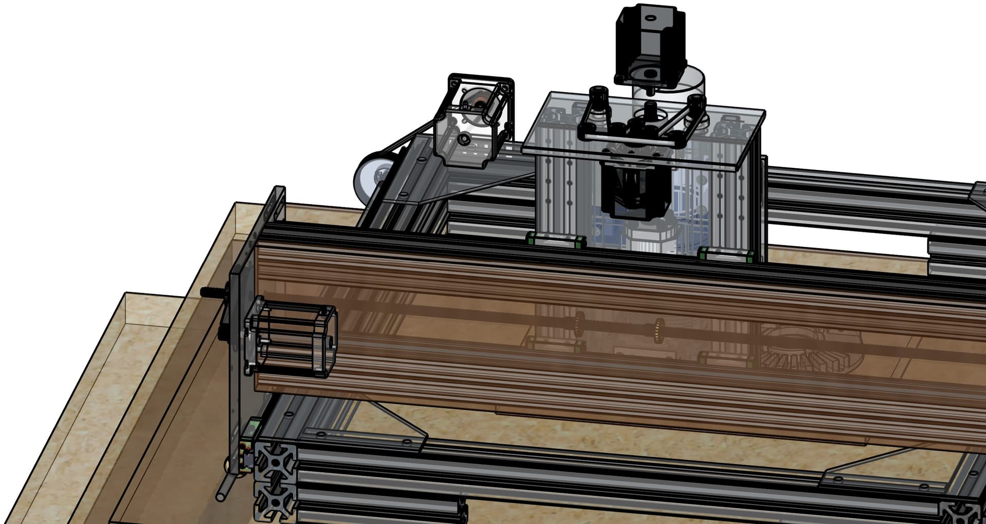
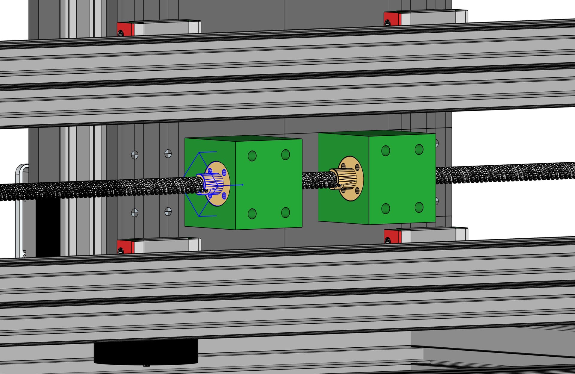
I think you could keep the Y block spacing the same without losing any range by shifting them both forward like this, unless it causes loss of range in the forward Y direction. But I think the spindle will still run into the front wall first.
1 Like

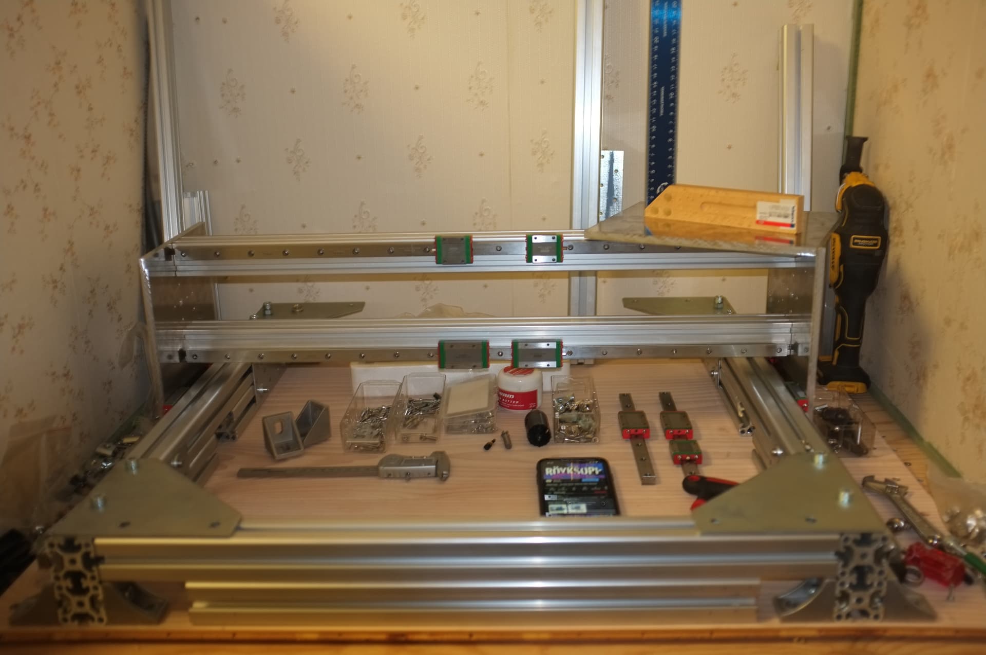
The linear rail I bought, for the Z axis, is a cheep HIWIN MGN15 lookalike, which I intended for the small blocks, but unfortunately the rails and blocks are not 100 % the same. The original HIWIN blocks run fine on the spinoff rail, but the cheep blocks put quite a lot of resistance in the movement, on the HIWIN rails. Not just running less smooth, but actually inertia for the motor to struggle with.
Maybe I should mix up’em balls between the Blocks and make a de-centralized production on continents. Are U in USA
")


")
That motor controlling the VAC_Shoe Z movement, needs to be a NEMA17 for there to be room, for the BALL_Screw mount bolt heads.


I wouldn’t exactly call this country united, but yes, I am in the geographical area known as the USA ![]()
Try mixing and matching blocks between different rails. Mine were all over the place, but I was able to find a combination where only one or two blocks were slightly looser than I’d like.
I look forward to seeing how well your machine works. I’ve been having progressively more vibration trouble lately, especially with 1/4" end mills. And I had to bump up my backlash compensation from 10 to 20 micrometers, so I think my ballscrews have worn in a bit since the beginning. If the spring loaded leadscrew nuts are able to handle 1/4" mills without vibrating, I think I’ll switch to those. Though I kind of doubt it, because I measured the spring force on one and it’s less than 1kg.
What would be really nice is if I could make a spring-loaded dual ballscrew nut with more like 10-20kg spring force. That’s about all the cutting force my spindle is capable of on a 1/4" bit, and theoretically SFU1204 ballscrews can handle 400kg so I doubt it would cause excessive wear or friction. The hard part is finding a suitable spring. Otherwise it’s just a matter of preventing the floating nut from rotating, and I can think of at least two ways to do that.
I guess one can find stronger springs ?
")

Edit: Just found out, that if the hole for the 8mm lead_screw is a bit undersized, it takes away any backlash. At the moment it does have some friction, but I will try to heat the screw and see if it will snug. Maybe I can print the thread ?
Edit Edit: Yeb, heating did the trick.
NB: When you smell the print outgassing, then its hot enough. Im not sure how it will span out heating the screw before inserting it in the nut, for it to lead the melt. When in the nut, the screw does have some wiggle. If its like those inserts, where the pre-bore leads the insert when heated, then I suppose one can just jam it in there.
When using 110v, do you draw twice the amps? What is the common fuse value in the US?