Custom Stator 135mm outrunner for 40KV motor

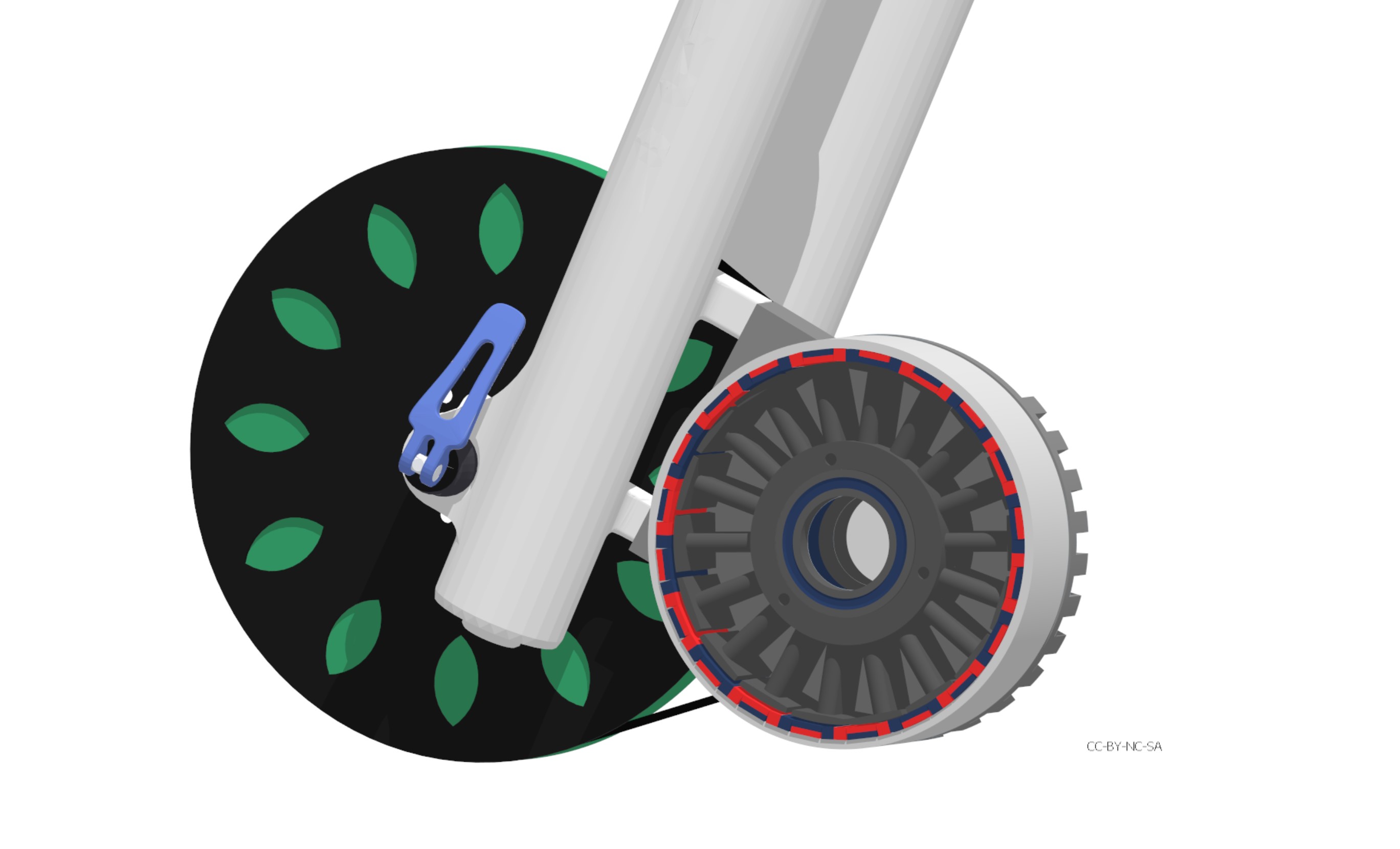
I rather focus on a system for chip extraction. With a Nema17 and a pinion gear, I believe it will optimize the whole vacuum story, if the vacuum nozzle/ring can move in the Z axis independently of the spindle. You could then make a much tighter fit around the tool without worrying about the broom hairs getting cut. The advantage of doing a independently controlled vac is the possibility to do a vacuum sweep where you plunge the bristles. That would involve closing the hole for the tool/spindle. or maybe it is stuck to the spindle, but the wall´s of the vac shoe can move, thereby allowing pressure on the bristles, to get in to those deep pockets. Maybe it is actually a advantage to have the vac shoe hovering over the work peace in some scenarios, where you don’t want the bristles limiting airflow. I guess a cloth will not interfere with the tool if used as a flexible vac membrane.

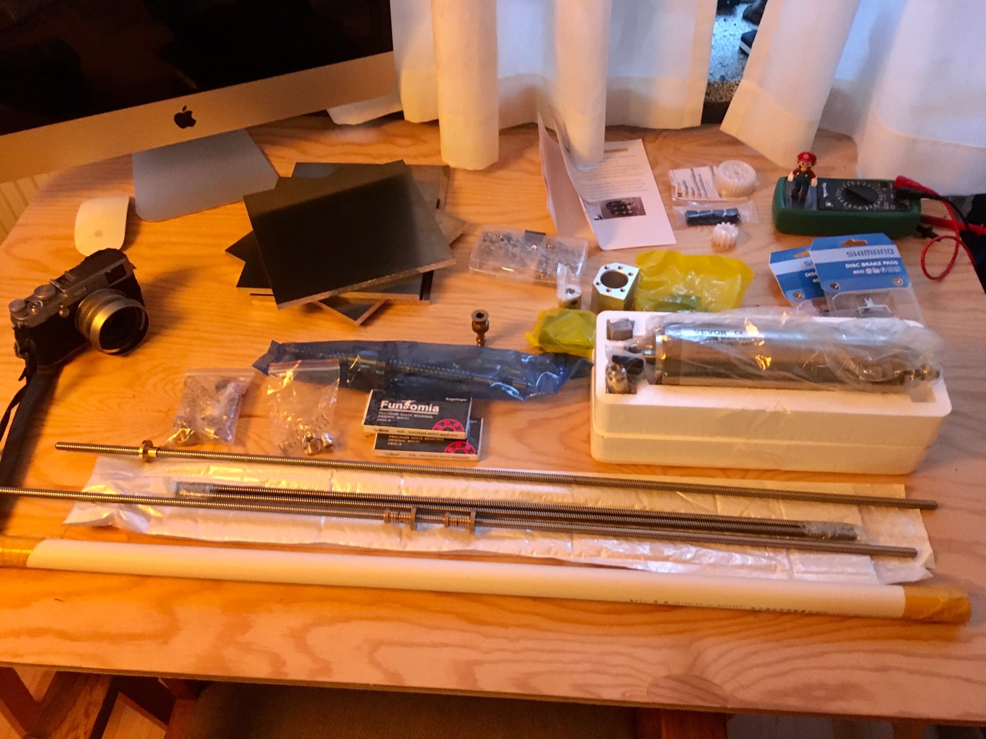
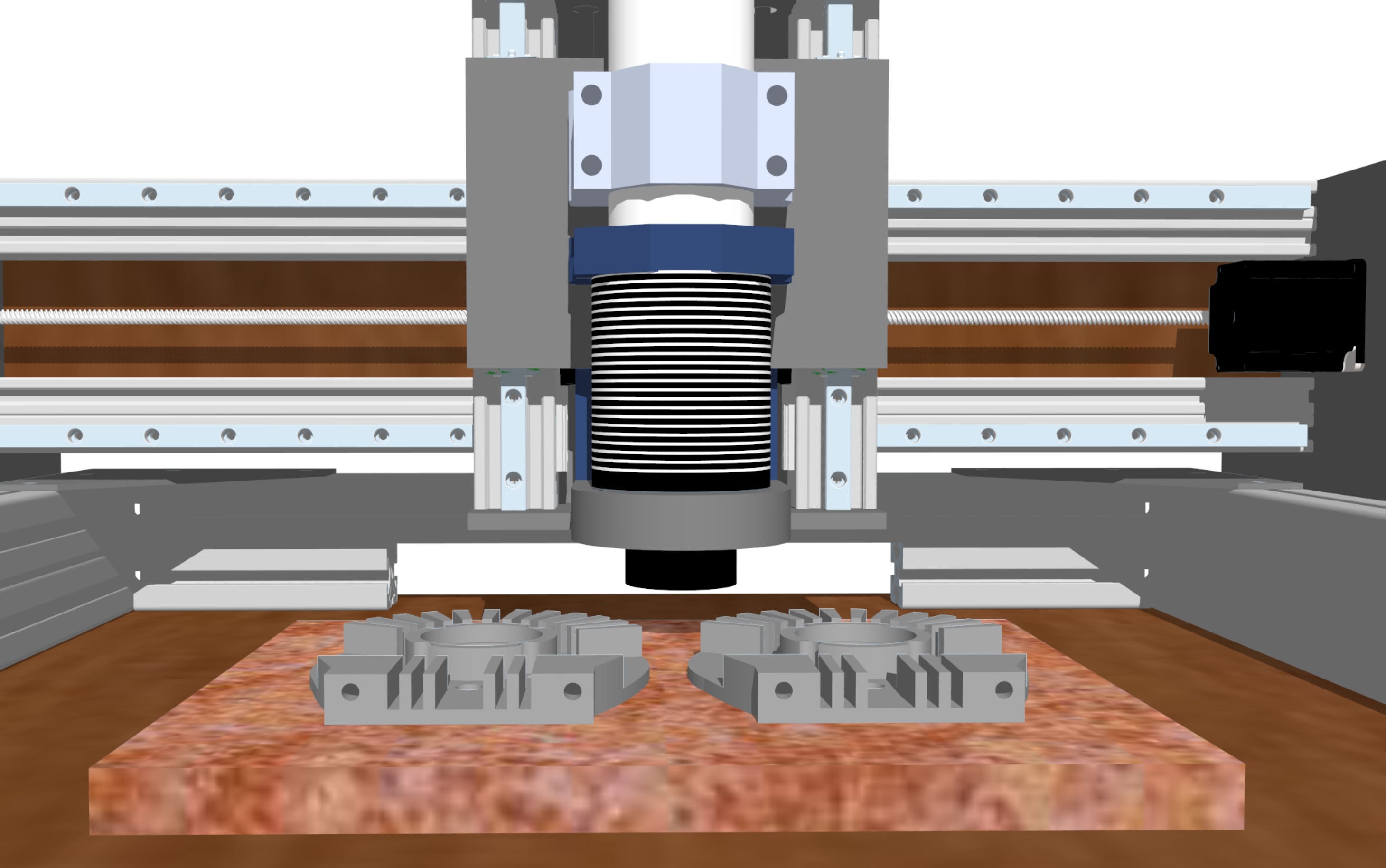
Using this flexible hose. When compressed it should make room for changing tools and when extended it should move a few centimeters. It should have a detachable vac head/whisks.

Flexible hose N1 (Ø 60mm) - Flexslange N1 - Starracing Motorsport

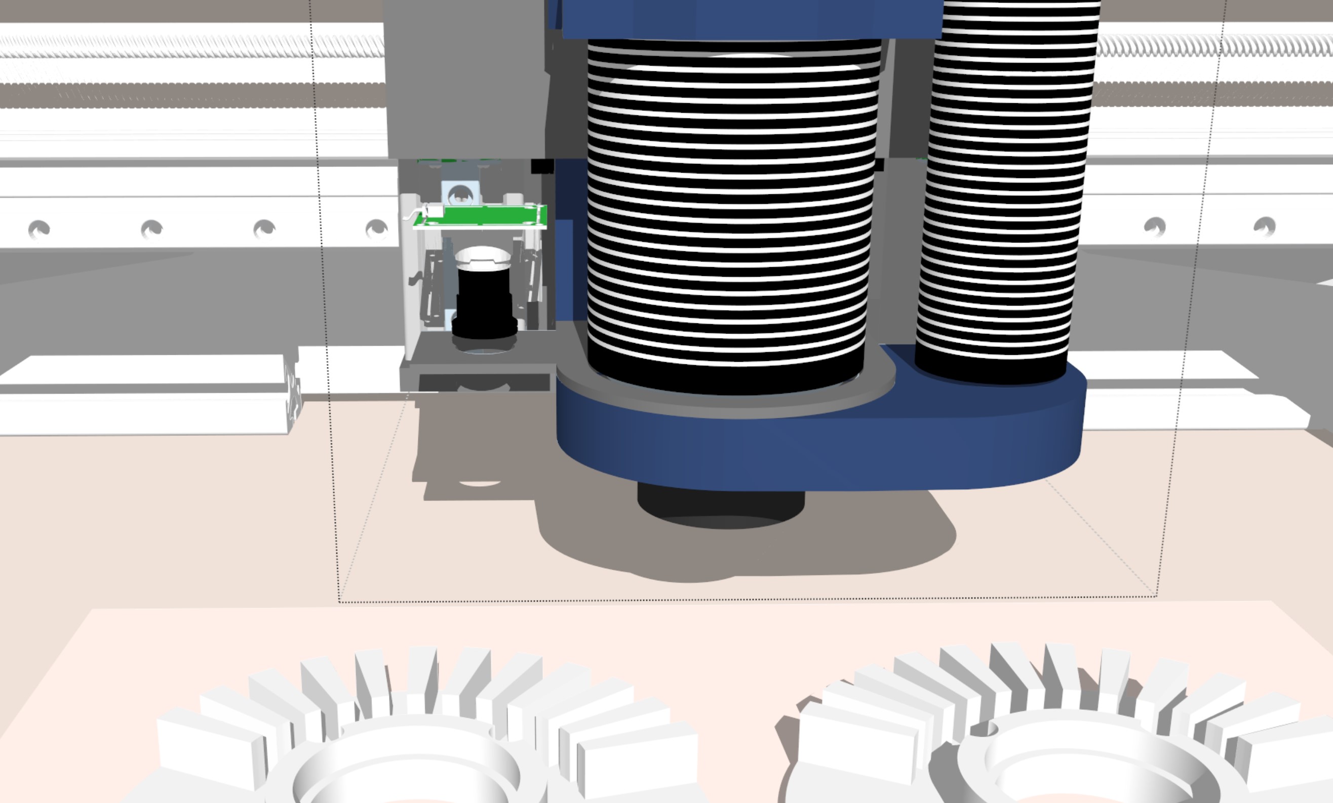
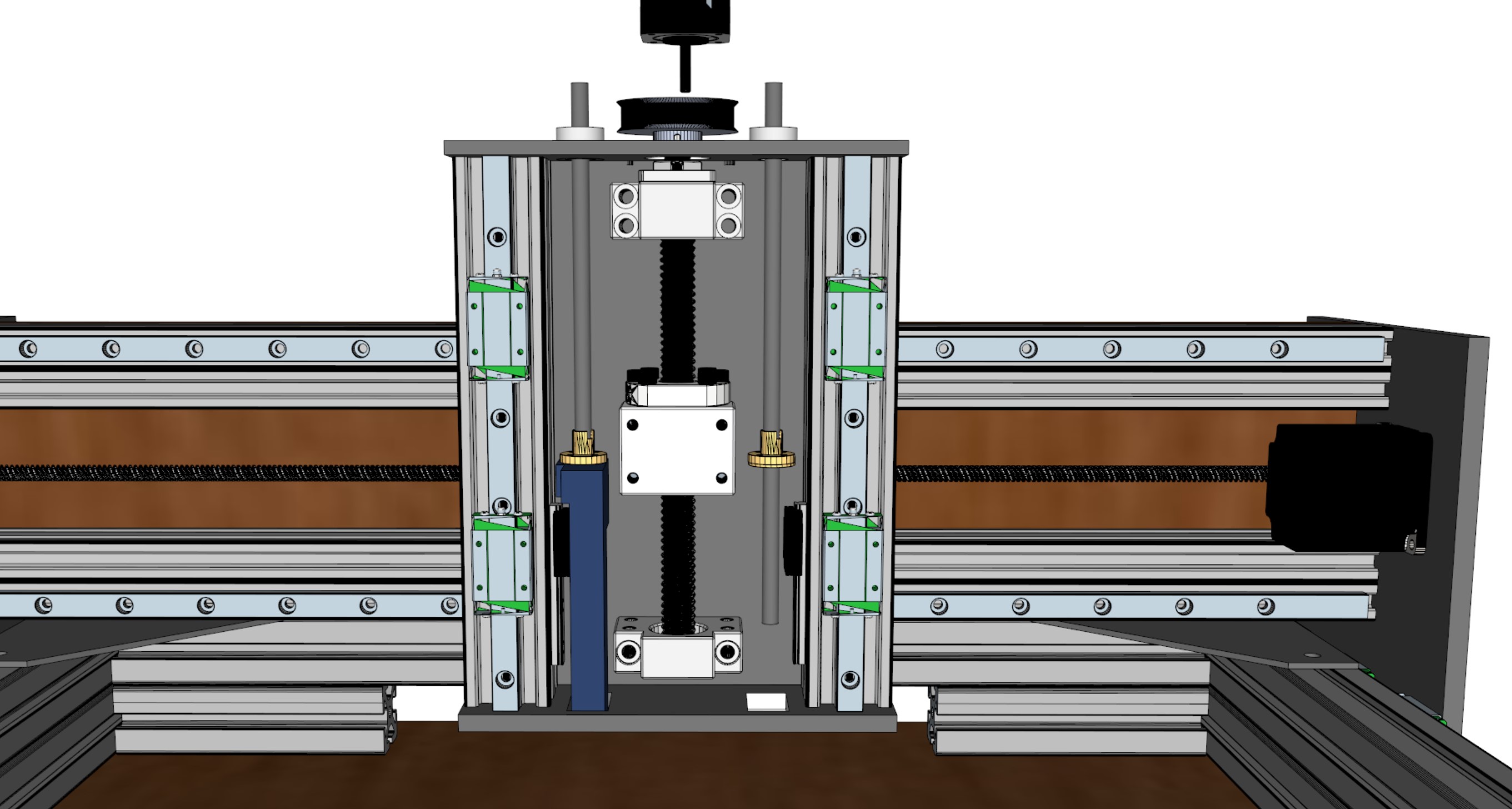
Here is a crude example.

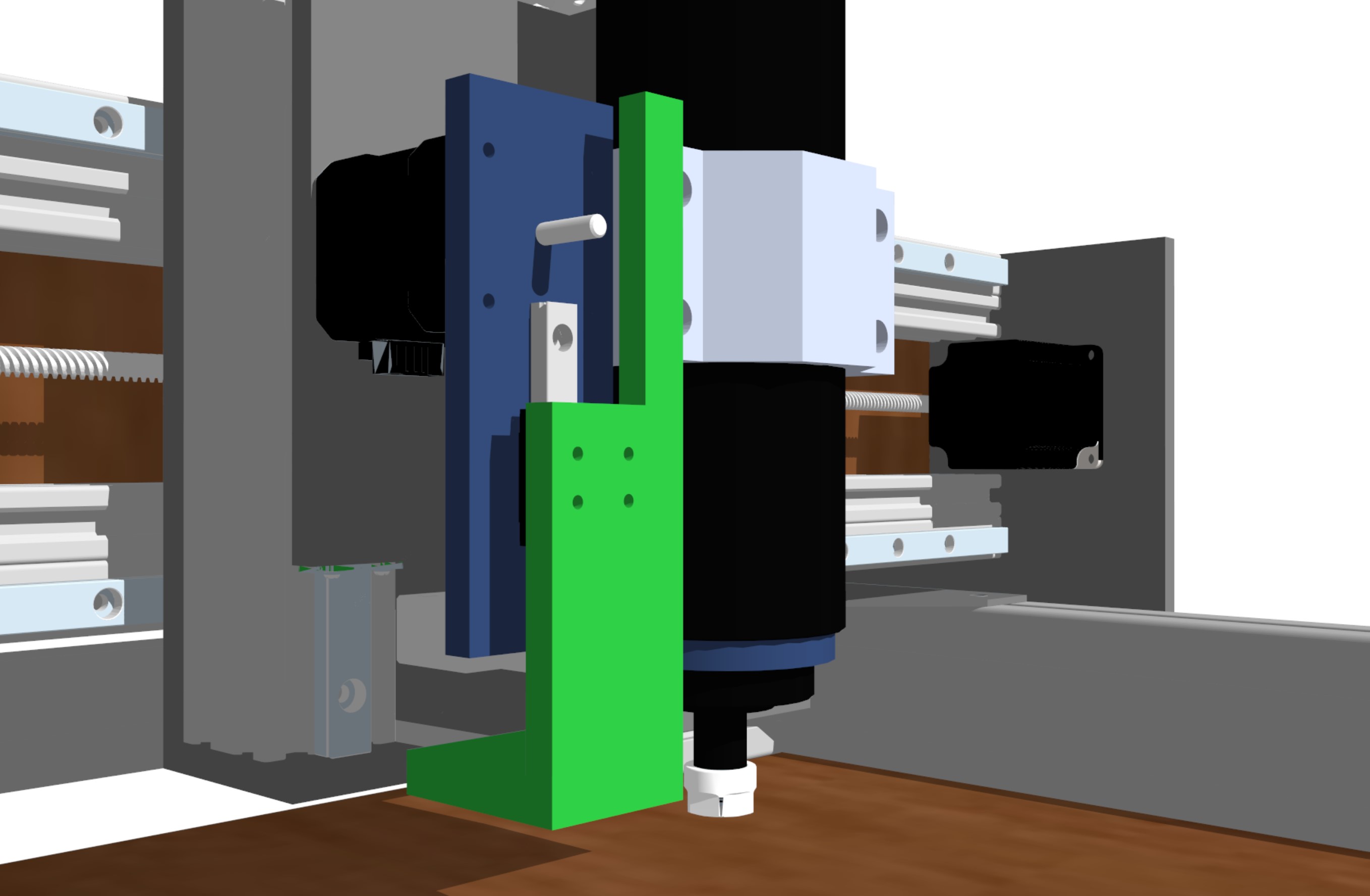
Actually, why not use some of all that space in the pillar: I believe we only need bearing in to top side, since the lead screw for the VAC is attached to that small linear rail, it can only go up and down.

The flexible air hose has to be fitted with the correct length for the length of the tool. Flexible hose can become 3 times its compressed length. If cutting contour, and you have the brush plunged like half the depth, that would create a smaller diameter airgap and thereby better air pressure to remove the chips. Of course one length should work within a range of a few centimeters.

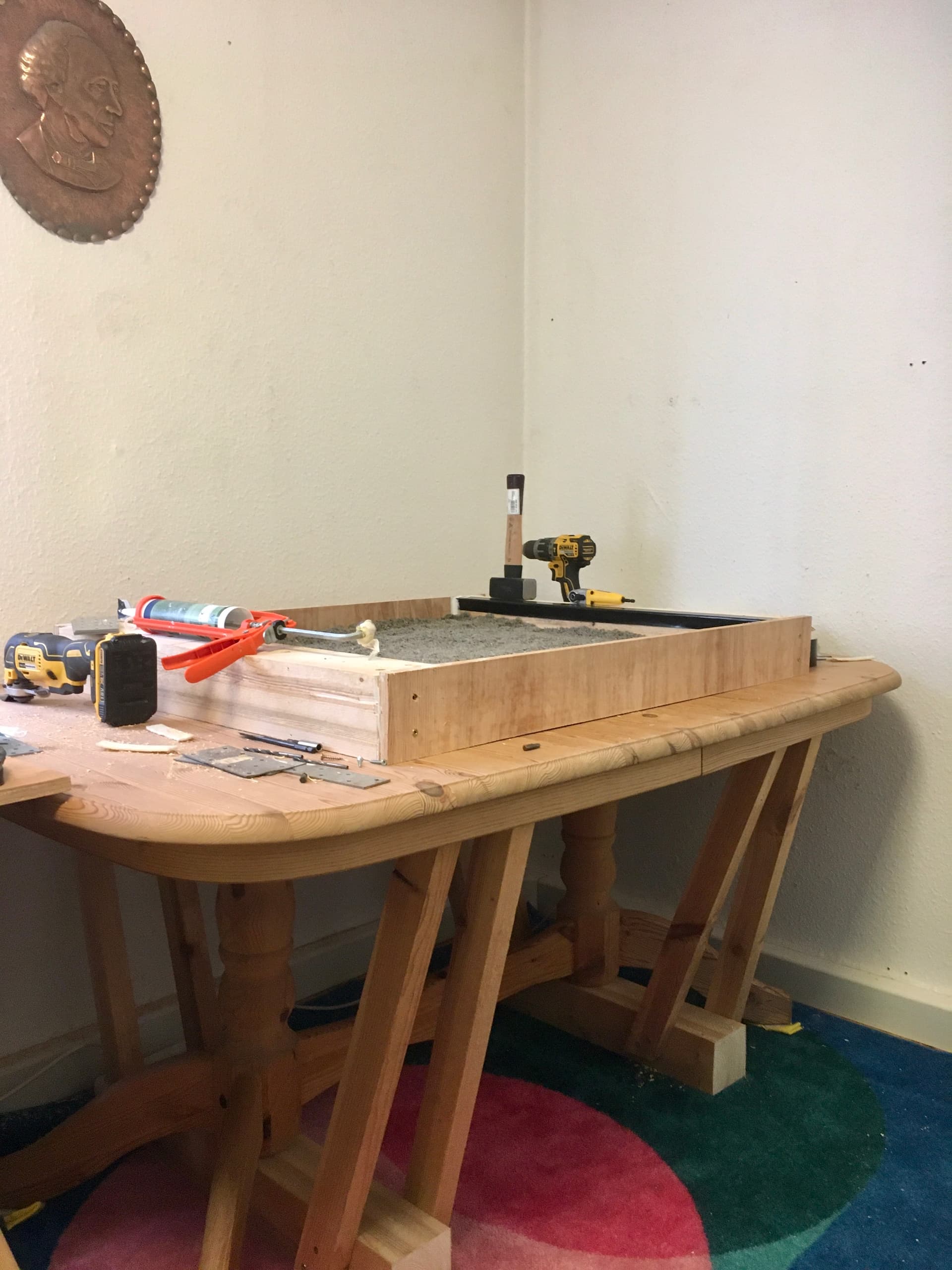
In the end the machine has to be setup for what ever surface you have and the size of your work_peace.

Maybe the flexible air-hose can run along the wires, in parallel , on the X-beam?

Added 5MP USB camera for visual homing. Since it is mounted to the VAC bracket, it can focus on the work peace by moving up or down. This means we can drill small fiducials in the peace for later re homing/calibration. Like a PNP does it, when mapping the peace. Maybe it can even detect corners.

With the camera, we can also make it hunt for chips after a job, like a visual robot vacuum cleaner.

Imagine if you set your machine to calibrate the camera by drilling a small diameter hole and then measuring/seeing where that hole is compared to the camera. Have I dreamt this?

Do you think it can machine soft magnetic iron composites (Coated iron ingots)?

Probably. The iron ring in that hoverboard motor wasn’t too terribly hard. But I did have to take a pretty fine chip, which resulted in a zillion sharp magnetic needles scattered all over the place, so hopefully your fancy chip extraction will be effective. I have my rails and screws pretty well protected, but they still found plenty of other magnetic surfaces to stick to. I cleaned up most of them with a neodymium cube in a bag, and got the stuck ones with a lump of tacky putty. Nonetheless I did get poked several times, which was not pleasant. I’ll try not to cut into the iron ring next time :slight_smile:

HÜganes has a 120mm Ø 20mm tall SMC blank for prototypes. If staked, maybe with a few mm of pure iron, then you have a 40mm sintered SMC stator prototype. If doing that, it would almost be a pity to cut it down to 115mm Ø. Dont know how these prototype ingots compare to a final part, when it comes to eddy-losses. When they press the powder, some lubricant is mixed into the powder, so the green part will release the mold. Their prototype cylinders are rated for 150C. Tensile strength is 15 MPa

Compared to aluminum 15MPa would be like cutting butter. Heat would be the biggest concern, since the coating is some kind of resin.

https://www.hoganas.com/globalassets/download-media/sharepoint/brochures-and-datasheets---all-documents/somaloy_prototyping-material_1334hog.pdf?mode=brochure#page=4

Looking at the datasheet, the core losses seams a bit high. If I understand correctly that is. The frequency stated in Hz is the frequency of change in magnetic direction, right? So that depends on how the motor is configured and commutated, as to how many electrical revolutions (eRPM) it has?

Fundamentals of operation
The BLDC motor’s electronic commutator sequentially energizes the stator coils generating a rotating electric field that ‘drags’ the rotor around with it. N “electrical revolutions” equates to one mechanical revolution, where N is the number of magnet pairs.

So 1500 rpm (mechanical) would be rpm x 10 (N magnet pairs) = 15.000 eRPM / 60s = 250 Hz

For a 500g to 700g stator, that is actually not bad. In the 20 to 40 watt range. In the lower rpm is where the current is needed, so for higher rpm the currents should be lowered, which it will.

Aha, the 5P somaloy green part has a tensile strength of 15MPa. That means you can heat treat it and get higher strength. If those prototype ingots are 5P somaloy green parts, that is. It would be like machining a green part. The 3P material has higher strength but worse performance.

From what I understand, the disadvantage of milling somaloy green parts, is that the outer layer of isolated (coated) iron powders grains will short circuit. It has been proven to correct this by dipping the part in acid for a given time.

This is a example of using SMC. Because we take advantage of the 3D possibilities not present in laminated stator design, we can curve the stator teeth, where the copper is wound. This is no small detail in the final design. Bending the copper over a sharp 90 degree corner is not optimal.

Also, using the 3D properties, we can embed the bearing into the stator.

Parts are starting to show up. Just ordered the closed belts. Big shoutout to robotdigg.com, these guys have what ever belt or pulley you may ever need, plus Nema23 (76mm) for 16$. Closed belts are below a $.

Will probably take another month before all parts are here and it’s fully assembled.

Was thinking, why not use the UGS to close the loop, having a separate encoder module feeding the main program with exact tool location. Like a virtual gcode machine. If then, the path is off by a margin from the gcode, then the program should take proper action. Pause, re-home (maybe), re-try path? Have been looking at TMC5160 and it’s encoder interface, but using step/dir it does not have encoder functionality. It’s still a nice driver IC, though. I believe it is simply too large a task for the stepper driver / MCU board to handle the closed loop, not to mention making Marlin closed loop.

If the UGS had a virtual encoder layer, one could adjust feeds and speed, so as not to lose steps, and if steps where lost, then correct the path and make a budget CNC way more precise.

It would require having eg. 5 quad-encoders connected to a single MCU, feeding those positions via USB. SPI for programming the encoders would require 5 Slave-Select lines plus the SPI interface. Some encoders has onboard memory to store eg. resolution settings. Programming each encoder onboard memory separately will save a lot of wires, but will be a pain to re-program when installed or at best time consuming, nonetheless possible.

Having a 12bit quadrature encoder on a stepper driving a 4:1 geared 8mm pitch lead screw would produce a resolution of 2mm / 4096 = 0,00048828125

If only concerned about X and Y axis (3 separate encoders w. ABZ interface) a SAMD21 may be sufficient?

Edit: To realize above method will require a interrupt based library, like this one. GitHub - PaulStoffregen/Encoder: Quadrature Encoder Library for Arduino

I’m not sure having 3 separate encoders (on a dedicated MCU) while writing the positions via serial/usb will work as expected, yet another experiment in the pipeline. It wouldn’t really make sense to implement, if we loose encoder pulses. Ultimately it depends on MCU speed vs encoder pulse frequency. I do believe it is important to have the encoders on the same MCU in order to synchronize the sensed positions.

According to the above lib. Doc. Page the teensy 2.0 (16Mhz 8bit MCU) has a maximum interrupt freq of 127 kHz. Not bad for a AVR.

If doing a feedrate of 762mm/min the stepper will rotate at 6.35 rps which translates to (6.35 x 4096) 26.000 changes in states (interrupts). Hmm :thinking: the SAMD21 runs at 48Mhz and it’s a 32bit MCU. The conversion from step/encoder pulses to mm could be done on the UGS side.

Hey, SAMD MCUs, at least some of them, have a PDEC unit… but only one of them AFAICT.

Maybe STM32 should be your go-to architecture for this. Most of the timers (general purpose and advanced control) can be put in “Encoder Mode”, and SimpleFOC even has a driver for this (in our drivers repo) :smiley:

Using the encoders via the hardware peripherals means you’ll get zero latency processing of the encoder signals with no MCU overhead at all. The hardware just handles it.

I think in this way having 5 ABZ encoders on one MCU would actually be possible. Otherwise the interrupt load might get a little high, esp. at higher speeds.

1 Like

Hey, that does sound wicket nice. I was actually thinking to try the SAME51 with just 3 encoders. Two for Y axis. It has DMA on the USB port, so transfers could happen without MCU intervention. That would more or les leave the interrupt routines. Perhaps the Z axis should also be included, it wouldn’t change much, so minimal pulses/interrupt from that axis and it would be nice to know if it strays.

Made the proposal to UGS, they do have some good arguments regarding those servo-stepper add-on drivers with encoder. One argument is that the CPU/UGS program is too sluggish for what I want to achieve and that the closed loop should be introduced in the driver layer not in UGS. The best argument for doing it would ultimately be driving down cost, although those Chinese servo-stepper drives are incredible cheap. Another argument for doing it would be to use AS5147 for up to 14bit quadrature output, which will make a direct drive application possible with good resolution. Also, it would be possible to use linear encoders at a affordable price tag (with the AS5311). Actually, the best argument for implementing the closed loop into UGS would IMO be the visual aspect of knowing how the machine behaves at all time. The feedback loop would not just be a machine thing but a human-machine thing.

How far are SimpleFoc with stepper experience. From what I gather here and there it seams people are abandoning this use case ?

I agree. While I work a lot with Java in my business life, its not the first-choice language for real-time control applications :rofl:

Well, there are no plans to abandon it, and quite a few people get it working… but far more people who use our library use it with BLDCs, so we’re more focused on that.

Also there is an inherent problem to doing FOC with high pole counts like the steppers have - the higher the pole count, the more accurate the sensors have to be to capture enough resolution to give good results within the small space of one electrical revolution, and the faster the MCU has to be to achieve the same RPMs. So its also just more difficult to get good FOC results with the steppers. Luckily, steppers tend to run slowly.

While we don’t really get into this too much in the docs, I believe one of the main parameters for the FOC algorithm working and the quality of the results you get has to do with bandwidth / sampling times.

Loop iteration speed and sensor latency both have an effect on the performance.

Normal is to have a loop like:
Sensor -> (ABZ) -> MCU -> (PWM) -> Motor
I honestly think changing it to:
Sensor -> (ABZ) -> MCU -> (USB) -> CPU -> JVM -> CPU -> (USB) -> MCU -> (PWM) -> Motor

will introduce such latencies and irregularities into the timings of the control loop that your performance will be terrible… but there’s only one way to find out :wink:

At that point I’d consider it much better to connect the sensor to a RPi via SPI, and eliminate the MCU as a middle-man on the one side… in fact you could probably run the FOC and PWM generation on an RPi as well, and the RPi can directly run UGS.

But I’m not sure I buy into the whole concept.

I completely agree! There would inevitably be some latency, and the motor optimization wouldn’t be part of it.

Maybe it is time for a SimpleFoc nema23 board w. AS5147 or some other SPI encoder, although hardware QDEC would be nice too. This could also interface with linear encoders if let’s say the encoder ic was a breakout.

Regarding latency and the overall purpose:

A Open loop stepper CNC could be said to work in the blind, although many will say that it comes down to having properly sized steppers and corresponding drivers, so that those motor will not loose steps. That may be true, but it will still work in the blind and the user won’t ever know if steps where lost. There is feedback from the stepper controller every 200ms, but that feedback is the theoretical feedback of where the position ought to be, maybe not where it really is.

A CNC job may take hours and the accumulation of lost microsteps therefore may lead to actual flaws in the job.

What I propose is to give UGS (universal Gcode sender) eyes :eyes: despite it having latency, the idea is to make it see if the controller is off course. The purpose is to optimize the machine so it doesn’t make mistakes in the blind. One way to do that would be what I propose. Is it superior to other ways, nope, but if it makes the machine correct microsteps losses during the job, the controller will stay on target and you will know that the job was done as it was supposed to within the encoder margin of error.

Performance wise, a open loop CNC may or may not be spot on. It’s kinda like a gamble and you find out when you put the caliber on the final result.

Even with terrible latency, the point is that during a long multiple hour job, the errors should not accumulate.

Ok, let’s say it is possible to achieve this control loop with a single MCU and have those quadrature encoders sitting on the steppers like breakout boards. The system would be so simple compared to actual hybrid-servo-steppers.

As I see it, it would start to make sense to do a custom hybrid-driver if the machine was using nema34 or larger motors exceeding 3 amps. For budget machines, usually open loop, the proposed feedback loop would certainly be a upgrade. If at some point I figure out, that my nema23 are inadequate, then I’ll probably do a custom SimpleFoc hybrid-stepper driver.

1 Like

By the way, I’ll let you know when I start machining a custom motor. This CNC build story is kinda getting out of hand and is perhaps somewhat of topic, even though the intention is to experiment with a custom build stator for a BLDC intended for SimpleFoc.

Missed microsteps do not accumulate. When the current vector gets to the next full step position, the higher torque can jump over any missed microsteps since the last full step. But if that’s still not enough, then your chances of catching up begin to dwindle as the current vector gets farther ahead of the physical position and torque decreases.

Personally I’d use some awesome outrunners if I were going to bother with closed loop :slight_smile: But I doubt you’ll be able to overload NEMA23 motors with tooling that fits in an ER11 chuck.

Another possibility would be to use encoders strictly for logging. Don’t involve them in the motor control, but use them to detect missed steps so you know for sure your job succeeded.

1 Like

UGS codebase already has the ability to parse the polled controller “position”. Using the sensed position in combination and comparing that to the Gcode line should not be overly extensive for a skilled Java programmer.

Dots —> Lines —> offset —-> correction

The UGS visual interface takes the entire Gcode into a 3d representation. I propose to separate the layers into 2D representation and zoom in on the polled position inside a plug-in. By zooming in on the controller polled position, which has a 200ms latency, UGS should be able to pause a job if something messed up happens, eg. If the sensed path is diverting from the planned path by more then a pre-defined tolerance. That could possibly be the difference between a broken tool and not breaking the tool. As I understand it, the controller holds a buffer of commands for movement, but will react immediately to a pause. Such a plug-in would be the equivalent of having a person with a magnifying glass constantly checking if the machine is on track, with one hand on the pause button. Only, a person wouldn’t be able to remember the entirety of the Gcode planned path. Most likely the sensed encoder position would be ahead of the polled position depending on how often the position is updated (how fast it can parse the incoming datastream).

The next level stuff would be to introduce AI, or learning parameters for different materials and tools.

Hey,

I think there is definately stuff you can do in the space you describe…

For my machines, and I am not at all a pro like you guys, my understanding is UGS just sends the GCode and the controller interprets it and drives the motors. The GCode sending happens “asynchronously” to the drive, and is usually “batched”.
So if I want to pause the machine, I can do so only at the points the controller permits - it needs to be able to insert the stop, and then resume the following GCode commands. Depending on its implementation, this could be more or less immediate. Certainly my machines like to move for quite a few seconds before pausing, if I initiate the pause on the PC.
So if you want to correct positions I think it is possible, but there may be limitations.

I have to say though, since 10 million people are using their CNCs without this, perhaps its a distraction? Get your machine running and worry about this part only later, if you find it to be needed…

1 Like

Prepping base with 10cm sand for sound barrier and mass. Walls will also be isolated with sand. Don’t know if anyone has done a CNC inclosure isolated with sand, but I have read it is suitable for soundproofing. It’s gonna be heavy, so table is reinforced. Someone discarded that table in our yard :slight_smile:

You may think it’s going to be hot in there, and it will if there is no air change. So it depends on the vacuum setup to keep it cool.

#Sand is liquid

Just received the MC stator.

This is for a YZF R1 1000CC race engine. The center hole is 42mm, so perfect for the BB30 bearings, I hope. If its too tight, I might have to sand a bit, and if its too loose, I will probably glue it in. This MC stator is the most dense I could find. It has three layers of copper windings, and is wound in a star config. Ive just measured it to have a resistance of 0.8ohm. Under any circumstance I will have to re-wind it, so I will probably make it delta-config. Its 115mm OD, The core stack is 24mm and those extensions holding the windings is 33mm. This I will have to say is perfect for the eMTB purpose/concept… Time will tell.

Since I plan on using 14S (52v nominal), it will dissipate 80w through the windings and use 520watt @10amps / peak´ish, in its current form/configuration.

How much heat do you think we can dissipate ?

80w / 9 coils (18 total) is 8.88w per coil.

Warning! The fumes from that stator is toxic and a potential showstopper. If I will ever put this concept into production, we will have to find a non-toxic alternative for corrosion protection.