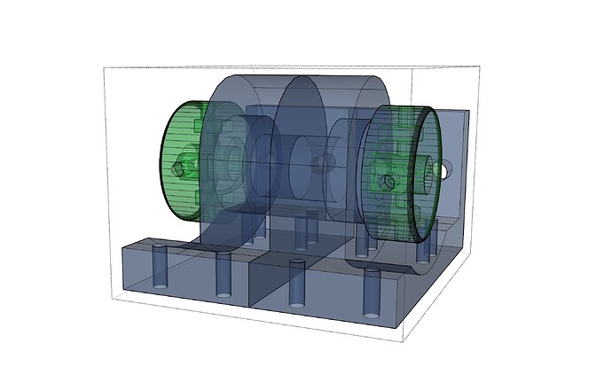
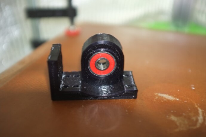
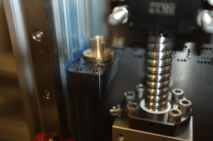
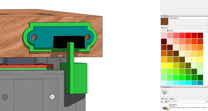
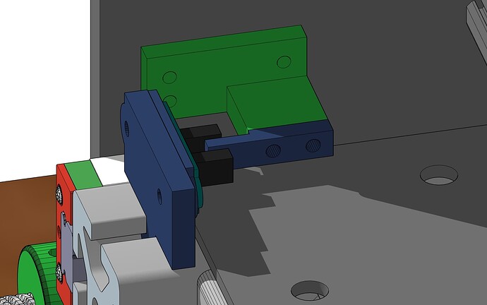
Progress; Y axis bearing assembly is in the printer. Ive opted for two bearings in either end of the lead screw, in a dual print design, to avoid overhangs. Had some issues switching to Alloy 910 Nylon. It turned out to be a bad hotend sensor.
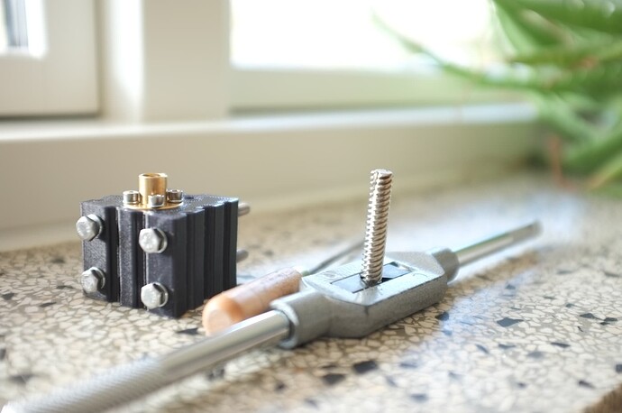
Made these lead screw tightening things using OpenScad. Its really just a pulley without the teeth.
First attempt with Nylon Alloy 910 on Garolite. It did take a chunk out of the buildplate…
Bearing was pressed in after sanding the seam.
Edit: I know this 3D print stuff is not BLDC related, but now that I have started ranting about Nylon Alloy 910 I really need to put this out there. I’ve tried the Goralite (composite) build plate, but I must admit it was under less than perfect conditions. The Goralite I got, was so thin, that I had to glue it to a 8mm plate. I strongly advise against doing that. The wood acts as an insulator, so the build plate wont properly heat, which will lead to some warping. After changing to glass with PVA glue, the warping is almost entirely gone and the print comes off nicely when completely cooled down. So with regard to the Alloy 910 specifically, glass is perfectly fine. (In my case I have a partially enclosed printer and I used a draft shield to insulate the print while printing. )
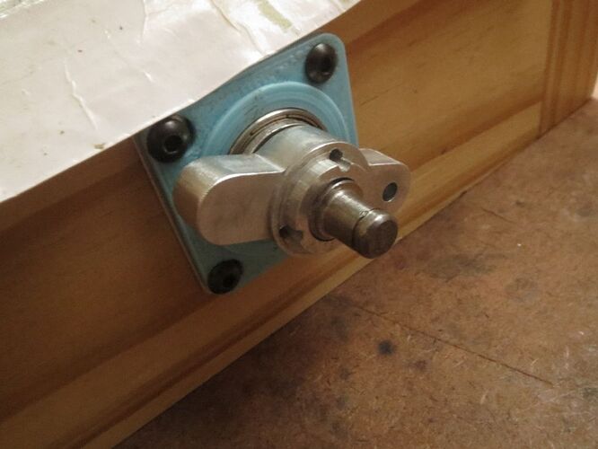
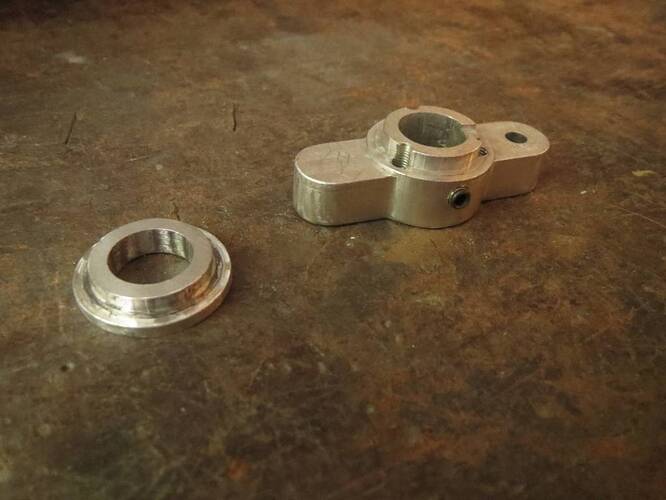
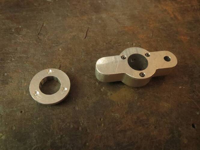
That reminds me, one useful thing I came up with for my mill is two-piece cranks which allow me to pull some tension on the ballscrews to eliminate any axial play from the bearings.
Originally the cranks themselves served as adapters to fit the ~11.7mm ballscrews into 17mm bearings, but then I made separate bearing adapters, and flipped the cranks so the flat side faces the bearing and has 3 threaded holes to apply pressure to the bearing adapter flange. This way makes it much easier to get the tension just right and balanced all around so the bearing still turns smoothly.
In your case the leadscrews can fit into standard 8mm bearings, so you’d only need a thick large OD washer to serve as the flange, a thin small OD washer/spacer to prevent the large washer rubbing on the bearing, and a custom shaft collar with 1 or 2 radial set screws to grip the leadscrew and 3 or 4 axial screws to apply pressure to the large washer.
Nice device !
It should be possible to 3D print the lead_screw thread and use the heating method to snug it tight. If doing that, one can make a tool to tighten the screw, like the ones you can buy.
Will make the experiment at some point. Maybe this approach will render the springs useless.
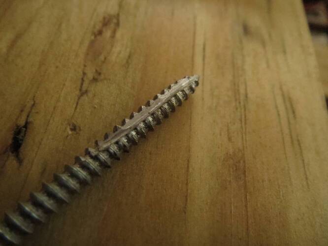
Mkay, the heating method is definitely inferior to DIY tap/thread cutter made from cutoff lead_screw. Made the groove with angle_grinder and made sure all the burs was removed. Installed the brass lead_nut and started the thread through it. That square in the image is the X axis lead assembly. Soon ready to hook up the machine. How time fly
1 Like
I just made a custom tap myself last week  Out of a ~3.5mm wood screw, because that seems to be the only way to buy a small diameter coarse pitch thread which I wanted for a miniature linear actuator. It’s surprisingly easy. I used a dremel diamond wheel, but otherwise did about the same thing. I also tapered the outside diameter toward the end so each turn cuts a progressively deeper thread, rather than having to cut full depth in a single shaving.
Hopefully your plastic threads will last a reasonable amount of time before having to be replaced.
I know, unfortunately I don’t have a Dremel and my anglegrinder recently messed up a battery which leaves me with one battery left. To be fair it was a mix of fear and laziness. Definitely it should have a tapered diameter and perhaps a third groove.
It will be interesting to see how the Nylon holds op when greased. I hope it can handle the grease ?
The vacuum shoe linear rail/actuator can be 3D printed to slide inside the 4040 aluminum profile slots. It won’t be moving fast, so the full torque of the stepper should be available. When greased up, it slides quite well.
So far so good…
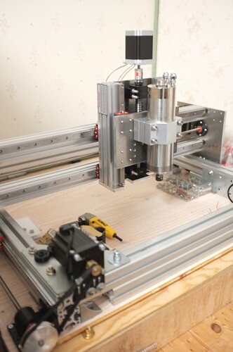
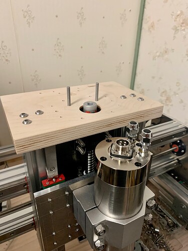
Will 3D print a additional holder for The Spindle to minimize chatter. Whats left is top_Z_plate, Z motor mount 3D print, endstop_mount_3D print, Vac_assembly, wiring, programming, test… Perhaps Closed loop SimpleFoc Nema 23 driver @ some point, the idea is definitely growing on me
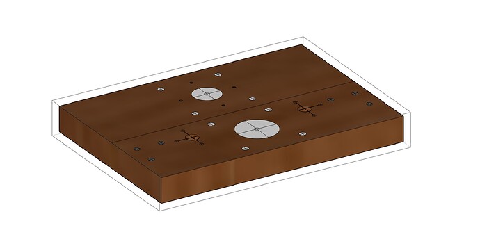
Was such a relief to use a pillar drill for the Z plates. Huge shout out to the Metal workshop at Godsbanen (Aarhus, Denmark). I wish I did that from the start. The cutout´s on the bottom Z plate (for the vac_shoe) was done on their vertical band saw.
Any ideas to reduce chatter when milling aluminum are welcome?
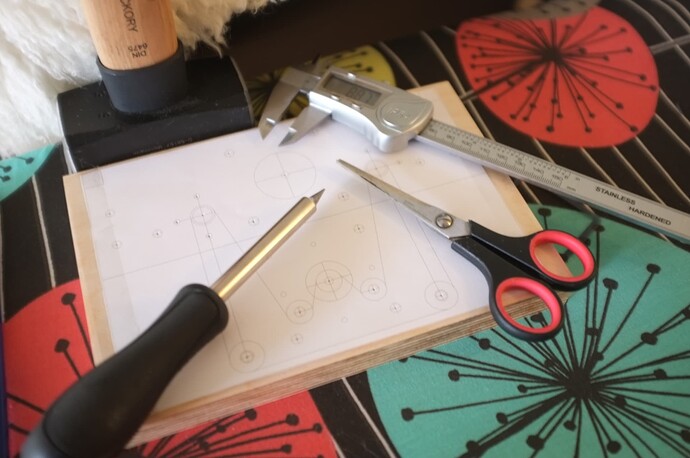
Here is an example of a drill stencil. If you decide to print it out on paper like I did, then measure the print before punching holes. I had to print at 99.8% scale to get correct scaling, your printer may be different.
From Sketchup, I found, that exporting to 2D (DWG) file, importing that to Rhino and then printing that to paper or to PDF for print on another machine works great. Just remember to check your scaling.
1 Like
Your mind makes it real
Redo: Unfortunately there are somewhat pour support for dual Y axis homing with Smoothieware (correct me if im wrong). Ill have to proceed with Marlin, which poses a challenge to UGS (Universal Gcode Sender) integration, if I’m not mistaken ?
Edit: Im sure dual Y axis homing can be implemented with smoothieware, but it will need some custom tweak’s. There are efforts being done to enable Marlin with UGS, so ultimately it depends on which has the best performance and which can be made to work with least effort.
