Custom Stator 135mm outrunner for 40KV motor

Could anyone be interested in participating in a group order for a custom stator, with integrated large diameter bearings. The Rotor can be CNC machined. The final diameter of the motor will be 140mm. The design is made with room for 3 layers of 1.02mm copper wire. This will give a relatively high resitance motor, rated for approx. 20 amp´s with 60 turns per winding.

Edit: From further research I can see that 1.02mm and 60 turns is unrealistic because of copper loss / heat generation. 1.29mm or even thicker is more suitable. This means less turns, but the goal is still a relatively high turn count compared to higher rpm and current rated motors (eg. 63mm outrunners).

I plan on making a Hallback Array with custom neodymium magnets. (H42SH 150C rated).

The cool thing about a 18 tooth stator, is that the Hall sensors can be placed in the space between stator teeth. So ive made 4.1mm spacing for 60 degree Hall´s.

The Low KV rating will produce around 1500 rpm with 52V. The idea is to use it as a geared direct-drive setup, where the belt sprocket represents the gearing. Ultimately by gearing the drivetrain directly, through the belt sprockets, the motor will have the equivalent torque of a much larger BLDC, similar to a hub-motor.

Maybe a 22 pole magnet array is better. It has higher winding factor.

You could potentially use a salvaged hoverboard motor converted to delta. Typical stats are 18kv wye, 27N30P, 105x29mm stator, 126mm rotor OD, around 2.5kg without the tire. Of course somewhat difficult to work with due to lack of shaft output, but they can often be had for free :slight_smile: And they have hall sensors.

Even if you use halbach, it is better to have some back iron https://things-in-motion.blogspot.com/2018/12/the-advantages-and-disadvantages-of.html
But according to expert motor designer Christian Lucas in this thread post #18 https://www.rcgroups.com/forums/showthread.php?3937215, it does still have advantages if you know what you’re doing.

One thing I’ve been thinking of trying is thin mu-metal sheet for back iron. In my case the goal is to construct an ultra-light rotor around it by carbon fiber filament winding, but you could use it inside a machined aluminum rotor too.

I see your point. But my point was to have much stronger electro magnets by higher turn count. There is not much space in a 27N30P compared to the 18N22P. Combined with the hallbach array, it can output higher torque. There are also stators for MC generators in 114mm OD, but usually they are quite narrow. I would like to have two 35mm ID bearings rest in the stator itself.

By the way, nice link to the video of that hallback array. I was thinking to hold the magnets in place using kevlar or glass/carbon fiber, Still the magnets must be mounted with epoxy.

@dekutree64

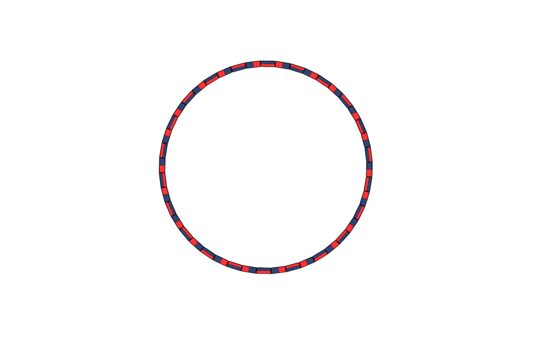
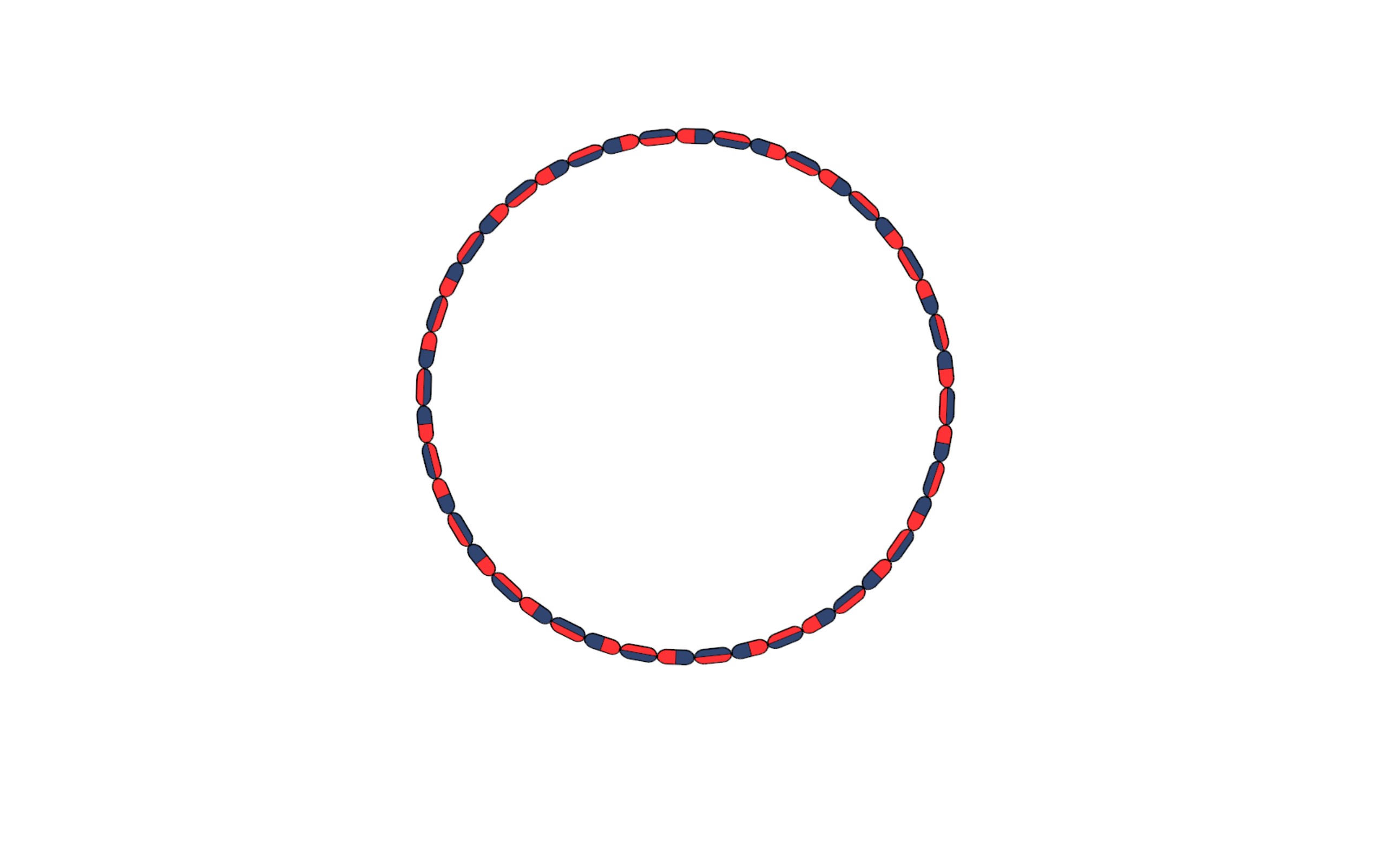
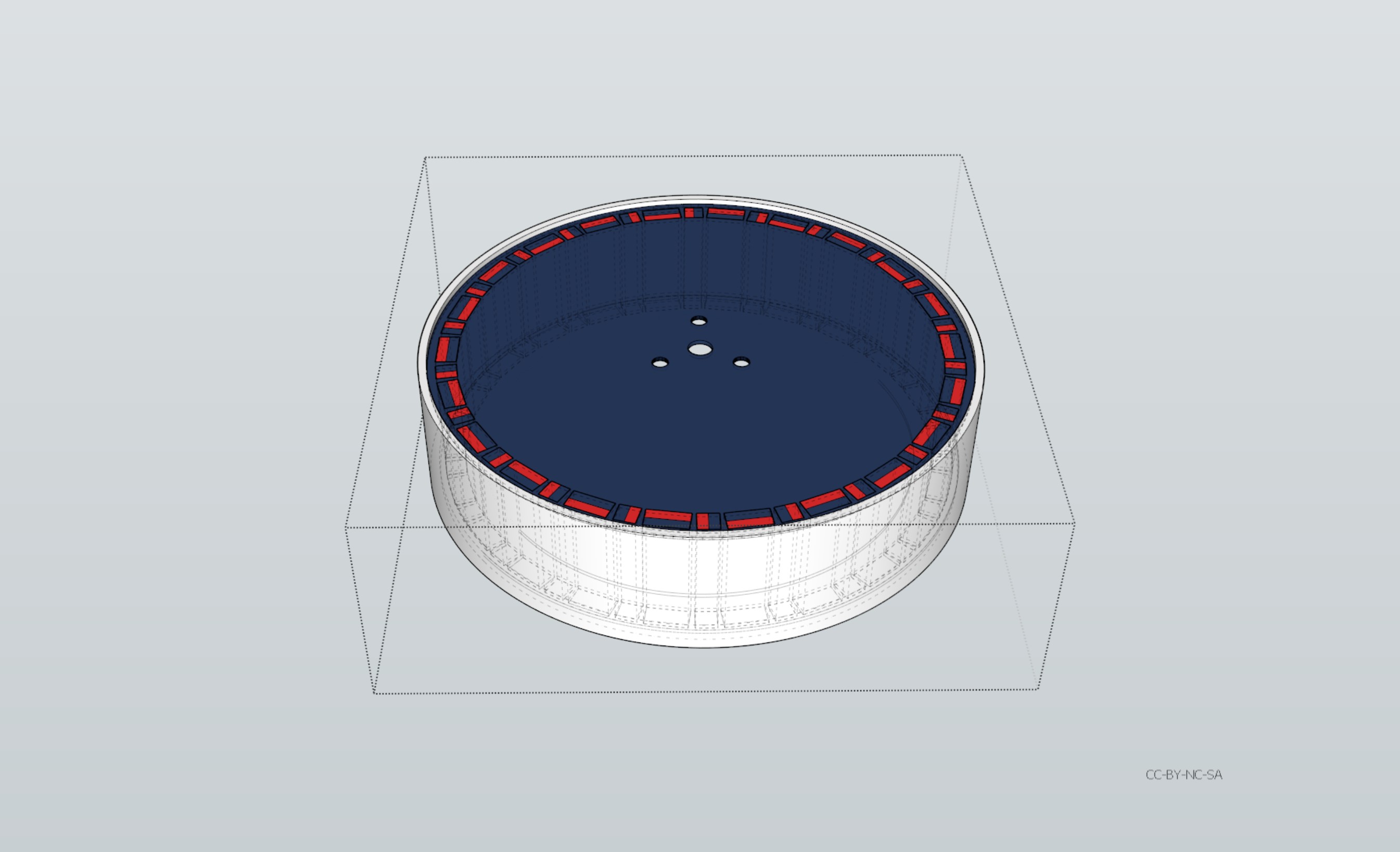
This design takes the added strength of the hallbach array using a lazer-cut stainless steel retainer. Ideally it could be stamped like the stator is produced. With a typical MC/ATV stator with a 115mm OD. (18 stator teeth) the magnets (30mm x 10mm x 5mm and 30mm x 5mm x 5mm) can be mounted to a 135mm aluminum pipe with a 4mm thickness. The retainer for the magnets should be backed with some more mass, so maybe carbon fiber plate or another stainless steel layer, bonded with the retainer. It should fit in a 2mm lib in the aluminum pipe,

You only get 0.85mm between the magnets.

With a custom 3D printed Nylon bearing holder/mount, it could have a high temperature rating. If injected molded, then 300C is possible.

Edit: I guess the retainer, not on the rotor lid side, could “just” be a Nylon ring bonded with some semi strong silicone.

I intend to go up to 1500 rpm, so definitely less centrifugal forces compared to a fast motor.

There is very little info on the MC stators for sale. The vendors apparently does not feel any need to write the phase resistance. There is one video on youtube where a pro measures different makes of MC stators. One had 0.5 ohm resistance another had 0.13 ohm.

Chamfering the magnets gives a 0.22mm increase between magnets. Remember, stainless steel is 3X stronger then regular steel. having 1.06mm should give a significant reinforcement. It does entail making custom magnets. The upside to the uniform shape of the magnets is that we “only” need two shapes, to create the array.

But then again, if you wanted to ensure the grade of the magnets to be 45SH (150C temperature rated). you probably need to make them custom anyways. The magnets should be battle-hardened with inside epoxy.

First the larger 10mm wide magnets should be glued in using a 3d printed holder/spacer. Secondly the smaller 5mm x 5mm will slide right in, since the magnetic forces will equal out the pull. Maybe you can actually make all the magnets align into position simply by gluing them into the retainer / rotor, if held in place. This could be achieved by first applying the glue to the retainer, and then have a 3d printed spacer for the magnets to hover like 5mm above the glue. But then again, you probably want a epoxy bond on the backside of the magnets, so they would need glue right then and there,

The ideal scenario would be to extend the length of the magnets and the thickness of the stator. But then again, there is also the sintered powder coated iron stators. They would allow a ideal scenario, where the bearings could be pressed directly into the stator.

The use case scenario for this 40ish KV motor is for a eMTB geared direct drive with a 3 to 1 gear ratio. So 3 turns on the motor is one turn on the bike wheel. In this case 27.5+ inch.

I can’t even find dimensions on motorcycle stators, much less electrical characteristics. But it looks like they all have far less copper than you could fit in the slots, so you’d want to re-wind them anyway.

Getting the magnets glued in there and spaced just right will be a challenge. Probably best to just buy some cheap magnets and try various approaches until you get a feel for what will work.

I think the ideal would be to also fill the space between magnets with epoxy so it hooks around the chamfer and helps to mechanically retain them, eliminating the need for a metal retainer lip. But actually accomplishing that seems difficult since you’ll probably have some kind of jig in the way while gluing the magnets.

I believe its a two step process. The battle-hardening is put on when the magnets are stuck.

If the epoxy is enough to hold them, that would be nice, but making a edge for the magnets to grab to will no doubt reinforce it.

Doing it in two steps, it may be trouble getting the epoxy to completely fill the narrow gap between magnets, or to keep from it running out afterward if you use low viscosity epoxy. It would be better if you could apply epoxy to the sides of the magnets before inserting them and then wipe off the squeeze-out, but then you have the access problem. Really needs experimentation to find out what will and won’t work. The answer will probably seem obvious in hindsight :slight_smile:

Then you would need to mold a silicone rig and use release agent.

That would actually make a great added layer for the rotor lid. Like if you poured the epoxy in.

I think I will ask Harley Davidson if they could make a sintered iron powder stator mold for their generator stators. That should hold some wire.

They vary in size. But you are right. Not much on phase resistance.

Ok, so I found some facts about MC stators. From this video, showing some dude measuring resistance and AC voltage on the phases when running 5000rpm. It’s show’s around 80 volts for a 0.5ohm stator.

Now, using the calculator on this site, translating AC voltage to Kv rating. It should roughly be a 46.5 Kv motor.

https://www.radiocontrolinfo.com/brushless-motor-efficiency/brushless-motor-kv-measure-a-motors-kv/#2

That’s less than a third the power of a 0.3ohm 18kv hoverboard motor. 22Ax8.3/18kv=10Nm, 22Ax22Ax0.3ohm=145W resistive loss. Motorcycle can only do 3Nm for the same heat. I wonder if it has ferrite magnets instead of neodymium, on top of the poor copper fill.

Here is a great calculator for calculating stator coil properties:

Coil Physical Properties Calculator (production-solution.com)

In order to make any meaningful comparison, it would be nice to know the wire thickness and turn count on the hover_motor stator.

Here ive taken the area of the “square” stator teeth of the MC stator and found a approx. Ø of 16mm

The more turns you can squeeze in the higher torque, depending on permanent magnets.

From these numbers Resistance = 0.037 x 6 coils = 0.222 ohm, I assume that the 0.5 ohm MC stator is wound in a WYE confiq.

Now take the 23 LBS and time it by 9 coils : 207 LBS of electromagnetic force (93.89 kg.) That is a pretty decent extra force on my front wheel times 3 to one gearing. Mind, that the calculator gives a force result from solenoid to metal, not permanent magnet.

For My Ally Is The Force | Star Wars: The Empire Strikes Back | StarWars.com

Reducing the outer tube diameter to 130mm and 3mm thickness. This will accommodate 4mm thick magnets and leave 0.5mm airgap. The rotor lid will have to be CNCéd, so will have to get a spindle and rebuild my XY machine.

Carbon fiber would actually make a decent substitute for the aluminum lid and it can be milled with a more aggressive cut (much faster to process).

Milling carbon fiber does create unhealthy dust, if not contained.

Check out this neat water container for carbon milling, it looks 3D printed. And of course the splatter skirt, brilliant!

I wonder if the water dampens the cutting sound?

@dekutree64

Regarding hover motor:

As I mentioned in orginal post, I made 6,5 turns. Original motor had 13 turns

Lot’s of good stuffs in this thread. One dude made a simulation with the stator.

At 10 turns the kV should be around 52 rpm/V with a slot fill factor of 30% and resistance of 105 mOhm. 15 turns per tooth should get you a kV of around 35 rpm/V in the WYE connection with a fill factor of 46% and a resistance of 158 mOhm.

Source

So, having the wire diameter and turn count we can do a proper comparison between the hover-stator and a 115mm 18slot stator with better room for windings and the actual magnetic capabilities of the stator alone.

Let’s go with 12 turns per tooth.

Using the same wire gauge (1.29mm) and 12 turns will give a 0.006 ohm (0.052ohm per phase in Delta config.) The bobbin length and día. Is just approximate.

But take a look at the numbers. 0.639 LBS per coil/tooth. Compared to three layers of 1.29 día. Wire doing 45 turns, 23 LBS per coil/tooth. Now, having such low resistance on the hover stator means it will use lots of current, this is what I want to avoid, still having high torque @20 amp.

Let’s try to hit a similar resistance. Using 0.812mm wire and 24 turns. And we are up 2.5 LBS per coil/tooth. Copper los will start to generate some heat at higher currents.

This is where the magnets come into play. The hover magnets are 2.5mm thick and probably neodymium. Does it have back iron? Anyways, doing 4mm magnets in a hallbach array, on the 18pole, will surely match the higher magnetic force.

One thing to keep in mind is the higher eddy loss on the hover stator since it has lots more pole-pairs. Having lower eddy-loss and “only” doing 1500rpm at max, means super thin laminations is not needed, but will improve eddy-loss if possible. Strike that, super thin laminations means more bonding/glue = less stator. Thinner isn’t always better in that regard. Those MC stators are made for 3000-5000 rpm and does not seam to have super thin laminations. If doing a custom stator I would probably go for 0.35 to 0.5mm laminations.

I guess, in the and, the motor needs to be balanced for highest torque with what ever heat we can manage. Like you rightly wrote, experience will tell.

Yep, water is the best dust containment. That printed skirt looks great :slight_smile: The water may dampen the sound a little, but probably there’s just not much to begin with. Carbon is soft, although it is abrasive. Diamond bits grind it up very easily, so you could try that if you have trouble with end mills wearing out quickly.

Hoverboard motors do have back iron. I machined my rotor last week and exposed part of it by accident. The iron ring is 4.5mm thick, except for the last 8mm is stepped down to 1.5mm thick so the screw holes that hold on the inside cap can be tapped into the aluminum and not the iron. The aluminum is cast onto the iron ring.

The stator laminations on mine are 0.5mm. 1500 mechanical rpm is 22500 electrical rpm. I’m not sure what kind of eddy current heating to expect from that, but I doubt it will be a problem. Hopefully balance won’t be an issue yet at that speed either.

Hoverboard motors seem to have half way decent windings to begin with, so I wouldn’t bother with rewinding. Just convert it to delta and use it as is. Sure you can do better, but hand winding is time consuming.