For practical purposes, your only limit is how sturdy you want the final part to be. I’d say maybe 0.2mm is the thinnest I could machine to accurate dimensions in a reasonable amount of time. Thinner than that and it’s basically kitchen foil, and will stretch instead of cutting unless you take very small bites with a very sharp bit.
That won’t be any trouble. Well supported by nearby material, and thick enough that the cutting force shouldn’t be enough to bulge it into the bearing area even if you drill the half-holes after boring the pocket.
Just ordered a 800w water cooled spindle. Planning to build a sound dampening enclosure. Do you think a Nema 23 on a lead screw w. 2mm lead, can lift itself and the spindle ? Can I use two anti-backlash nuts on a 8mm lead screw. I suppose it comes down to holding torque, not skipping steps. With a 2mm lead screw you get a resolution of 0.01mm?
Im thinking to use a meter of 4080U profile and 22mm OD 8mm ID skate bearings.
Im guessing the two anti-backlash nuts will hold the z axis, if there is no power on the NEMA23?
Maybe its actually a good thing to counter_weigh the spindle by gearing the lead screw w. a closed loop belt.
If it’s cheap Chinese, measure the runout on it before building your machine around it. In my experience Chinese ER collet stuff is useless, swinging the bit around in a conical arc instead of spinning it on its axis. And you can’t compensate for it, because each time you change bits, the error from the collet and chuck can either compound or cancel eachother.
I don’t think it will have any trouble lifting. Try a leadscrew calculator to get some idea how much leeway you have.
You only need one anti-backlash nut. Mount the real nut on the bottom, with the spring part on the top. The only time backlash comes into play on the Z axis is when upward pressure on the tool (typically when drilling) is greater than the weight of the Z carriage and lifts the leadscrew off the threads of the nut. The spring will apply additional downward pressure to delay that. Downward force is always fully supported by the mounted nut.
That U channel looks flimsy to me. Long lever arm between the cutting edge and the X rails, and U shape has terrible torsional rigidity = lots of flex in the Y axis. But I’m not so fond of the typical CNC router architecture in the first place. Good for full sheets of plywood, not so good for metalworking.
Ya i went with a 16mm ballscrew, although Chinese, I believe it will have the moderate precision I’m looking for. Have seen some ok descent reviews on those sfu1605’s. I think you are right about the frame. I will look at increasing the rail distance on separate beems.
The distance between the X rails is less an issue as the distance from the tool to the X rails. A single rectangular tube would be better for torsional stiffness. 50x100mm might do it. But then there’s no place for a ball screw nut. Belt drive would fit, but I don’t know if that works well for metal cutting or not. Rack & pinion would fit too, but then you have backlash.
My machine has SFU1204 ballscrews on X and Y, and they are pretty good. 6 micrometers backlash compensation gets best results.
Here is a 800W spindle cutting aluminum.
He or She also has linear rails, and a ball screw. It looks like they get away with a pretty high clamp on the spindle.

Looks to be working well. But assuming the X rail screws are spaced 25mm, that looks like around 65cm wide, which is less than 1/3 the flex of a 1m span.
I use a 10ml syringe with a tube on the end for lubricant application, so I don’t have to get my fingers so close to the cutter. Filled with Anchorlube (diluted with about 50% water), which is cheaper and less messy than oil. And a toothbrush for clearing chips.
Thinking back on my early struggles, I remembered that I bought a high quality ER11 nut and 1/8" collet, so only the chuck taper was bad. I think I was able to get consistent results that way, so I could at least calibrate out the error. But drilling holes was still a problem because the poor concentricity resulted in them coming out oversize.
Another thing to be aware of is that you need to measure the true cutting diameter of your end mills. They usually have 0 to -.002" diameter tolerance. I find 3 categories is enough. Mill a hole and stick a bearing in it. If it’s just right, classify that mill as medium size. If it’s too tight, the mill is small. If it’s too loose, the mill is large.
It’s maddening how precise you have to be just to get a bearing to fit in a hole ![]()
Ok, thanks for all the good pointers.
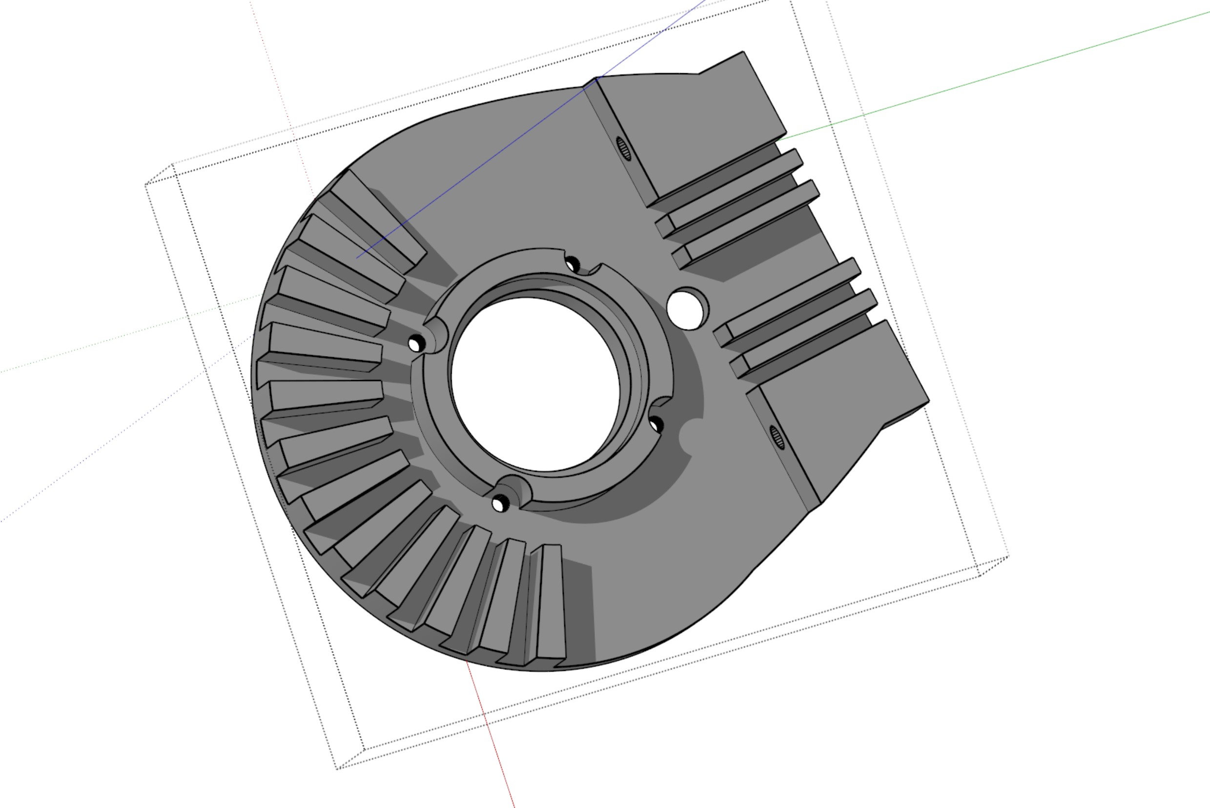
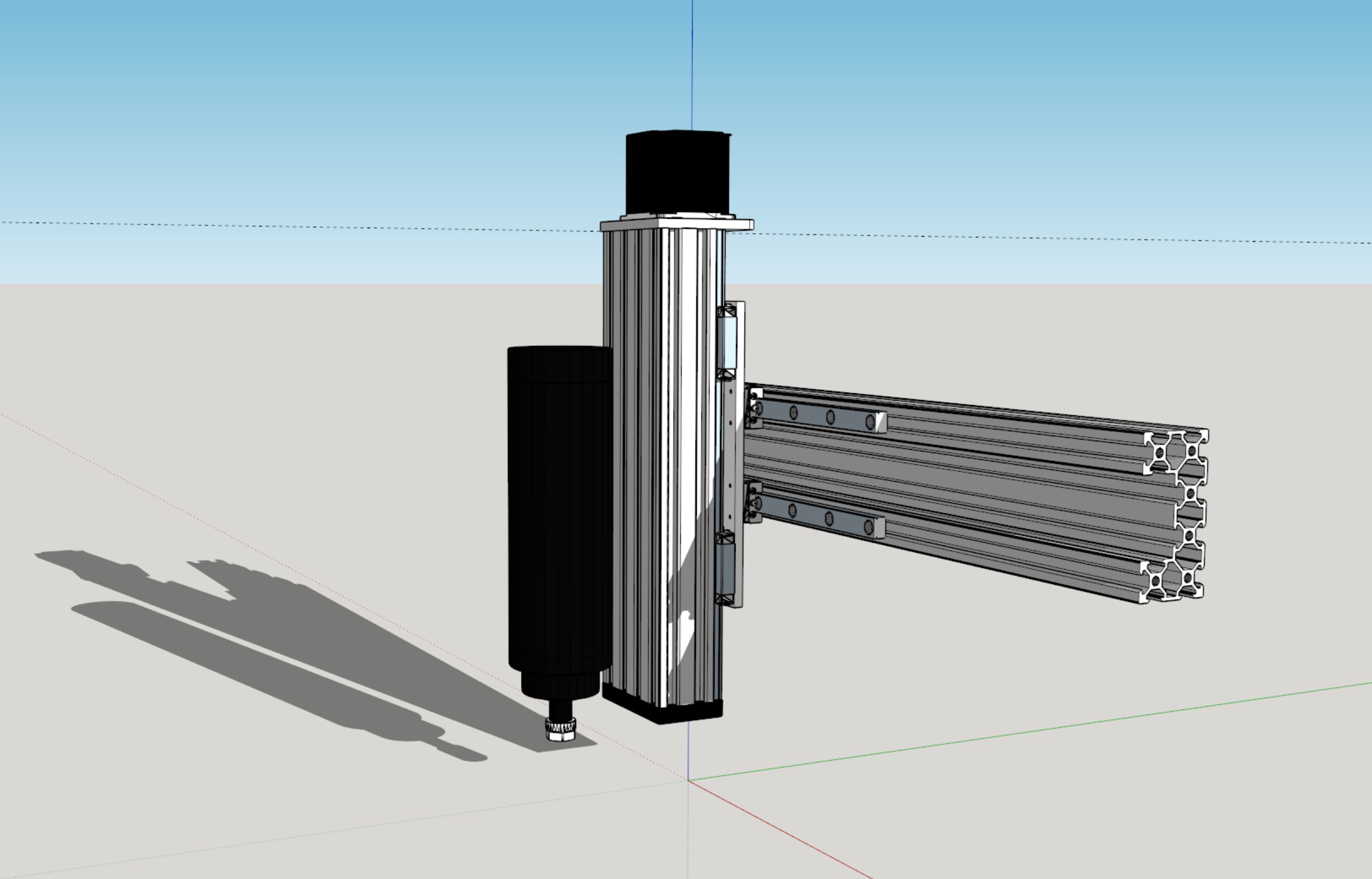
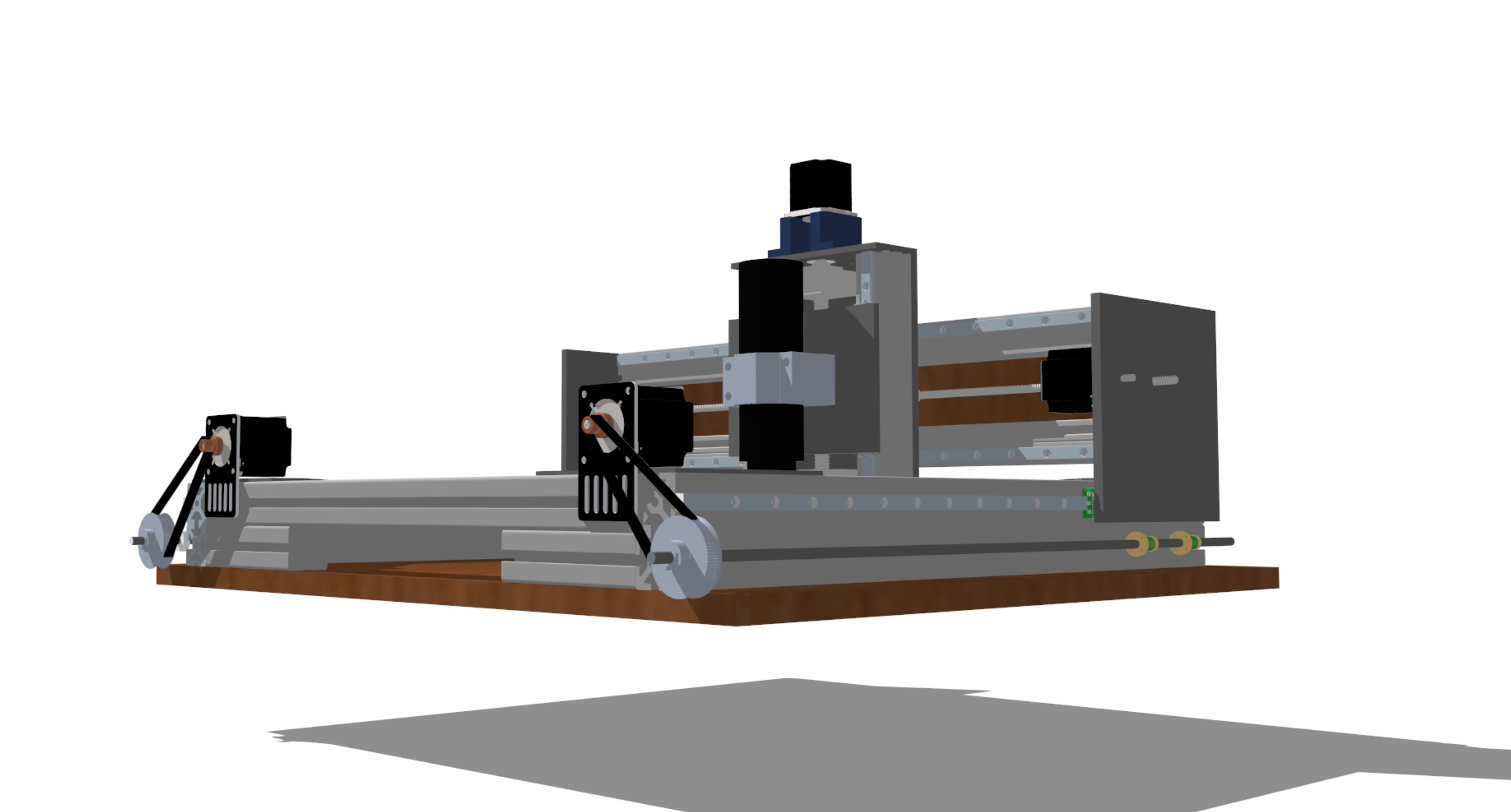
Ive settled on a design. I know, its a budget machine, but if it woks out, I will share it on grabcad.
The Y axis will be belt driven with two 9mm GT2 belts. One belt on either rail. Im contemplating doing visual homing, like it is possible on a PNP. If one had three visual points to calibrate to, then it should optimize the belt drive. Most likely the X-axis will be a lead screw. 8mm (2mm lead).
The idea is to drill all the holes and maybe counter sink some of them, by hand, using a stencil.
I will most likely put 3D printed support where it makes sense. Like inside the beam.

Use leadscrew for Y too. I think GT2 belt will be too elastic. 5mm pitch would probably work, but then you have frame rigidity to worry about, supporting the high tension on the belt. And mixing and matching X/Y drive mechanisms sounds like trouble in the first place (Z can be different though).
A GT2 belt can drive two Y leadscrews no problem due to the large mechanical advantage. My Z axis uses two 8mm pitch leadscrews driven by 60 tooth pulleys, so 1mm of Z movement requires 15mm of linear belt movement. The belt skips teeth before the NEMA23 skips steps when crashed into the bed (a useful feature, actually).
FYI you can run NEMA23 motors with the A4988 drivers on common GRBL boards if you stick heatsinks on the driver chips and a fan blowing on them. Mine are still fine after a large number of hours running over the past couple years.
Im opting for 4040 extrusions.
I prefer TMC stepper drivers. It would be very awesome to drive the X and Y axis with 6368 outrunners, that would require some belt gearing for sure. I suppose you hook up two car batteries to get 24V (140kv = 3360 rpm). Do you think 8mm lead screw for the X and Y would be strong enough with anti-backlash nut?
I will only have one rail on the Y axis, but im counting on the weigh for conservative cuts.
Good point, but so could a outrunner ![]()
I love TMC drivers for 3D printers, for the silence, ability to set the current directly in milliamps, and sensorless homing. Not much advantage for a mill though. And I haven’t tried driving NEMA23 motors with them.
And I am obsessed with outrunners (my spindle is directly driven by a modified Racerstar BR4114), but a GRBL board with steppers is so much easier and cheaper and works just as well. High speed on a mill is too scary ![]() So many ways to crash and damage things.
So many ways to crash and damage things.
I think NEMA23 motors would still be more than enough with 8mm pitch leadscrews. The lower mechanical advantage is partially offset by lower friction. But 2mm does have the advantage of being non-backdriveable, if you want to operate it as manual mill sometimes. I do, but all of my screws (SFU1204 and T8x8) backdrive, so drilling holes is all I can do with full precision. I need to add some mechanical locks for the axes. I can use the steppers as locks, but they jump to their nearest full step position when switched on.
The spring force on the anti-backlash nuts will most likely be overcome during roughing, but you should still be able to do high precision work by taking a gentle finish pass. Maybe two. First one to even out the surface due to the backlash leaving excess material in some areas, and then the true finish pass taking an even chip all the way around.
Good call on the 4040 extrusions. I wanted to complain about that, but I was starting to feel like a naysayer ![]() Looks pretty sturdy now.
Looks pretty sturdy now.
I have those Bigfoot TMC 2660 on a Azteeg X5 GT (NPC LPC1769 120MHZ ARM), but cant find any TMC 5160 in that format. That may be a future project. The bigger area can hold some larger FETs. The board has a 35v limit though.
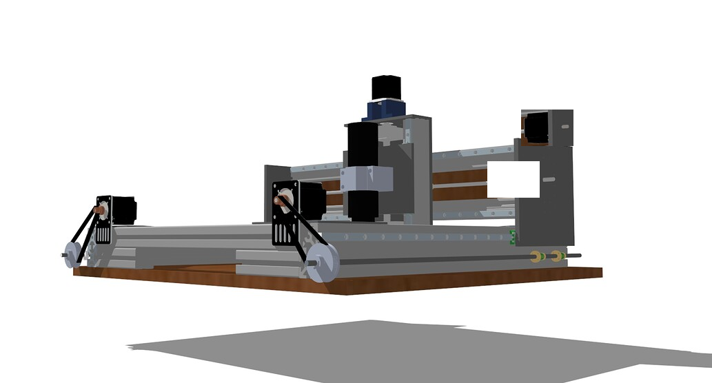
Have some spare wood, so came up with this enclosure. It kinda looks ready to ship out. I have found some 80T 9mm pulleys, so will go with that on the lead screw and 20t on the NEMA 23.
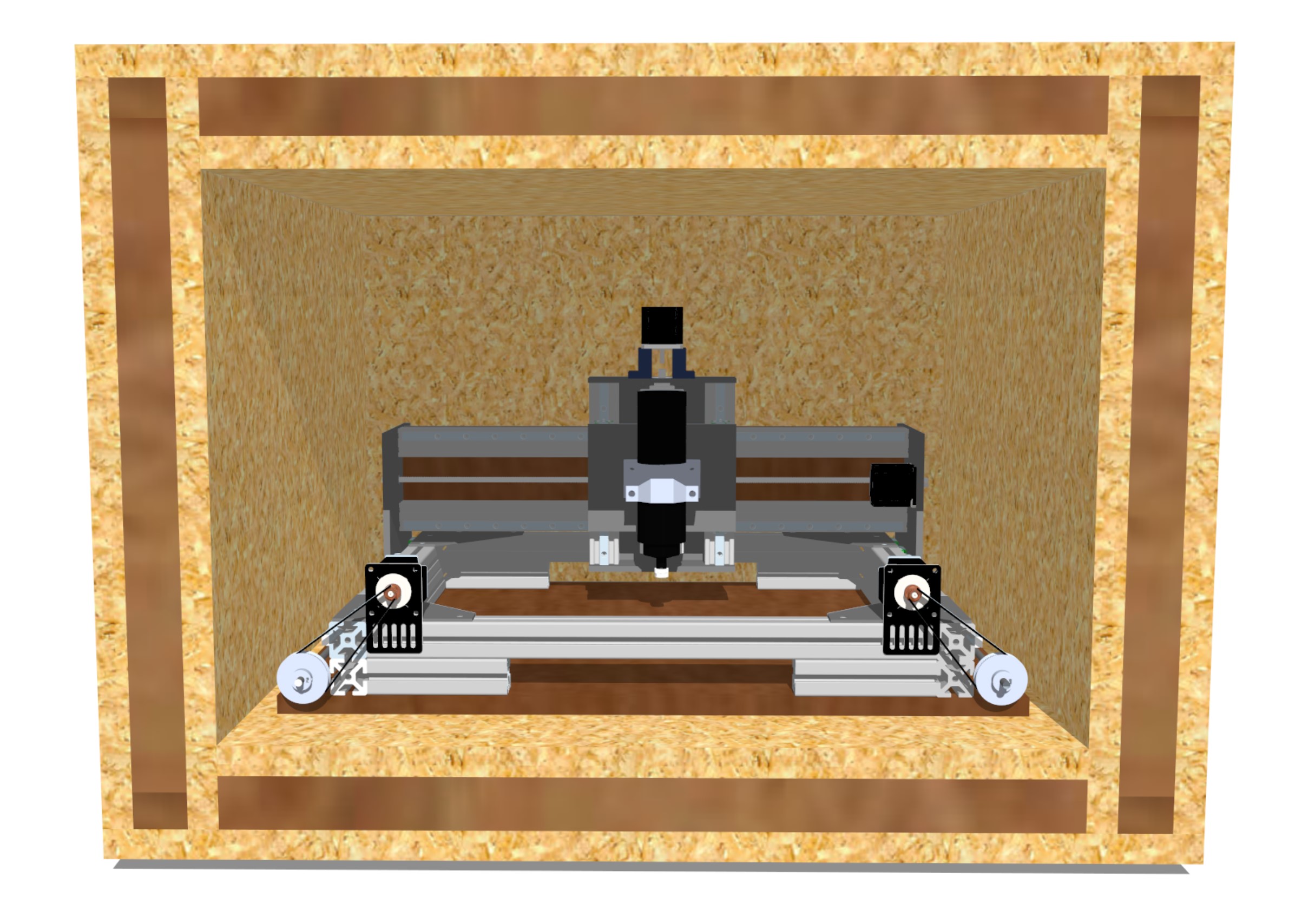
You should be able to tighten the belts on the Y axis by moving the motors in their brackets.
I guess 1mm of linear movement is 20mm belt movement. If you want the machine to be faster, for a different task, then changing the gearing will speed it up.
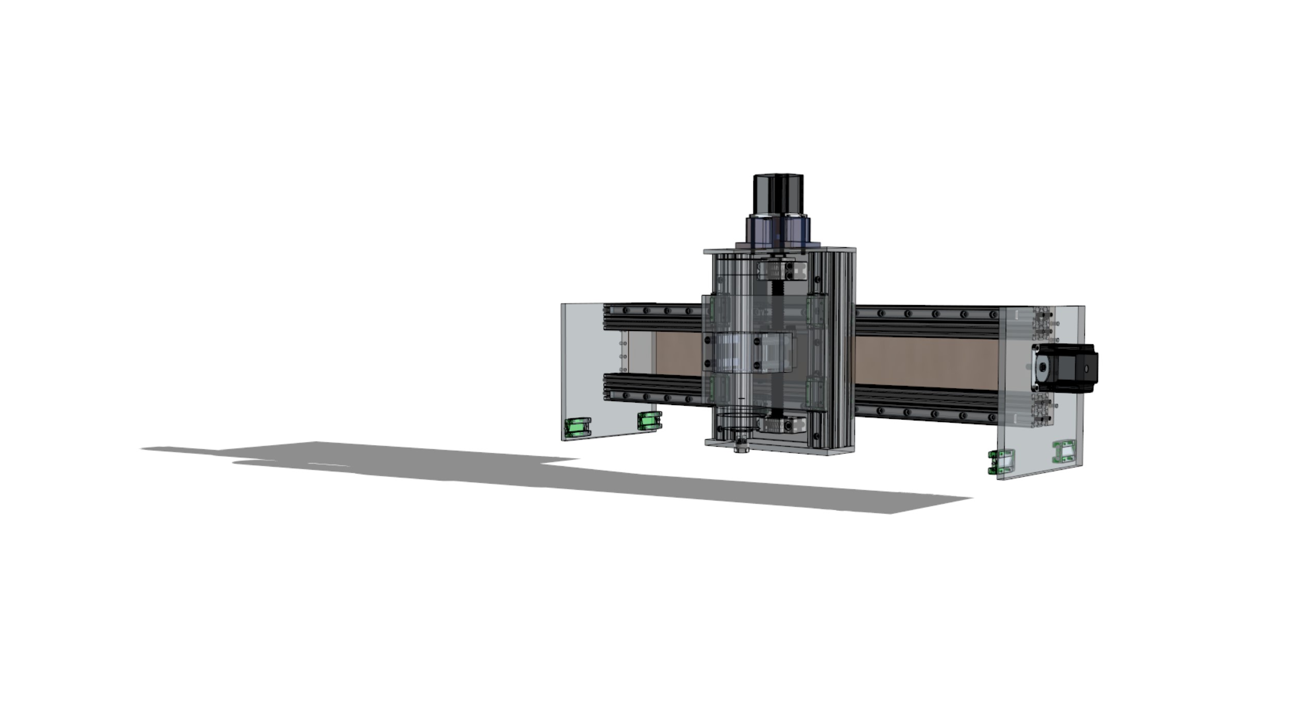
Its 80 cm. tall, and 1m x 1m approximately at the base. The work area will be approx. 370mm (Y) and 400mm (X). Since its 80mm tall, it can be transported on a EU pallet, which is 800x1200mm.
Regarding BLDC’s, I’m thinking to use a outrunner to make a DIY shop Vac with dust-separation. That would be a worthy task for SimpleFoc. If we can just create enough air-pressure to remove small aluminum chips in a relatively small diameter hose, that would also cool the tool, i guess?
Trying to go low with the lead screw.
If we can control the BLDC vacuum from software, it would be possible to use a mist-lubricant/coolant.
Edit: Mist cooling requires a compressor, which is another source of noise, so will instead look at squirt cooling/lubricant. The airflow from the dust/chip vac will help cool the tool. It will probably involve manually editing the g-code, to make a stepper pump dose the correct amount of oil or alcohol.
Will those Y motors be running in parallel from a single driver, or on separate drivers with separate limit switches for homing? I had imagined them being mechanically linked by belt, although that isn’t without its drawbacks either since it has to be readjusted to get the axes perfectly perpendicular every time you remove the belt for maintenance. But it does allow moving the axis by hand.
A thought: See if you can move the X motor up on top, above the 4040 extrusion so the Z unit can pass in front of it. Might give you a little more usable X range.
BTW, these are the NEMA23 motors I used. Very cheap and good NEMA 23 Stepper Motor - CNC Mill Robot Lathe RepRap Makerbot 3D Printer P13V | eBay
Mist coolant certainly would be good for running inside a closed box. Mine requires constant attention for most tasks, applying coolant ahead of the cutter and clearing away chips. Especially for 1/8" and smaller mills. 1/4" doesn’t seem to care much about coolant, except that sometimes it gets aluminum galled onto the cutting edge. I think zirconium nitride coating is supposed to help with that, but I haven’t tried it.
Ideally each motor should have a magnet on the shaft. But yes, I was thinking two endstops on the Y.
I see your point. The gear can just as well be on the inside, but then again, then I have to build the Box bigger. Right, on the top of the beam. I get ya. It may be better to have a lower center of gravity. The range is about the same.
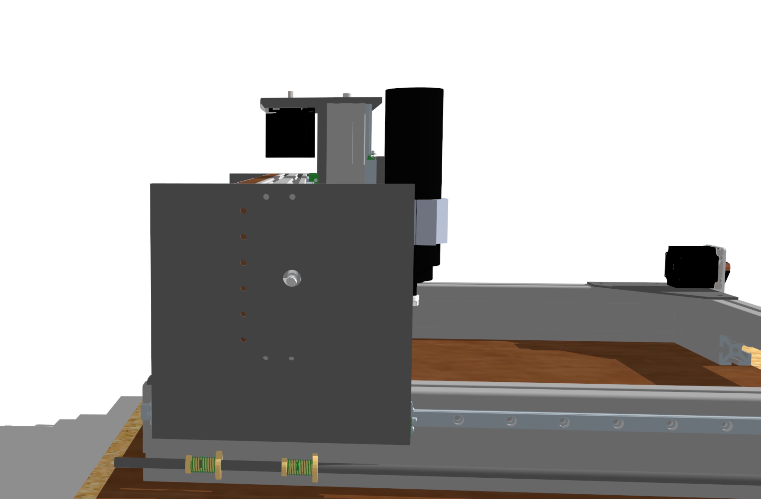
No, keep the Z motor where it was. I think the spindle will stick up about just as high when at max Z, so you can’t make your enclosure ceiling any lower that way. But having the X motor in front of the X rails looks like it gets in the way of the carriage, so I was thinking to move it up like this:
Why not increase the Z resolution ?
I have been wondering how one can make a linear actuator, for PNP purposes. Having such a “large” Z surface, could potentially have like 8 narrow Pick and place nozzles. In such a case, it might be useful to change gearing.
Putting the Nema23 up there does not increase the X by more then a few mm, since the profile and the linear guides make up that “lost” space. I believe it is better to built it more compact and with a lower gravity_center.
Oh, I think I see what you mean. I wonder if you could shift the Z rails up to where they clear the frame and you can use the full X rail width. Something like this:
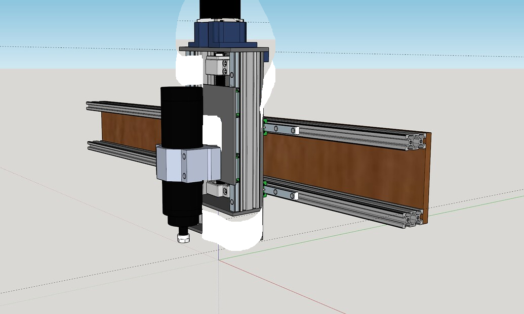
That would also give you more clearance over tall parts. But then the Z motor really does stick up a long way unless you flip it around the back and belt drive it. But if you do, then it hits the X motor when positioned like in my previous post…