Back-iron you say. That must add some weight.
Do you ever feel like things already happened. I could swear this conversation happened before. Maybe that’s why they call it echo chambers, you know.
Back-iron you say. That must add some weight.
Do you ever feel like things already happened. I could swear this conversation happened before. Maybe that’s why they call it echo chambers, you know.
I certainly have experienced deja-vu before, but not this time since I only just found out what the internal structure of a hoverboard rotor is like ![]() Save a screenshot so you can check back on it in the future if you get the same sensation again.
Save a screenshot so you can check back on it in the future if you get the same sensation again.
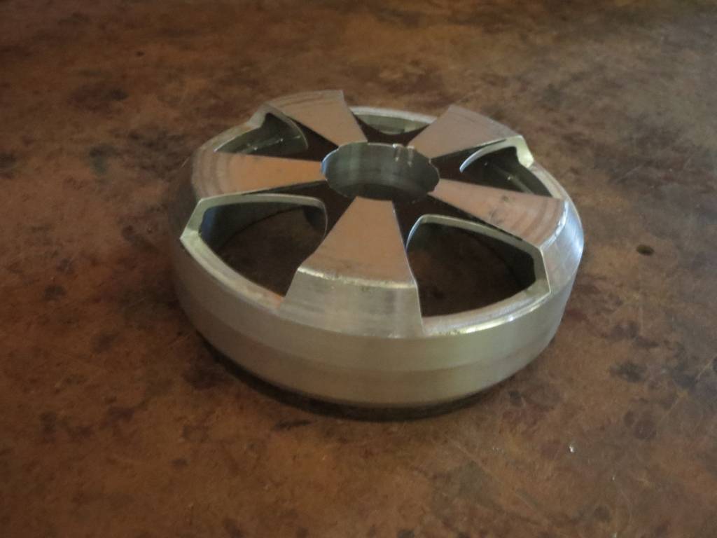
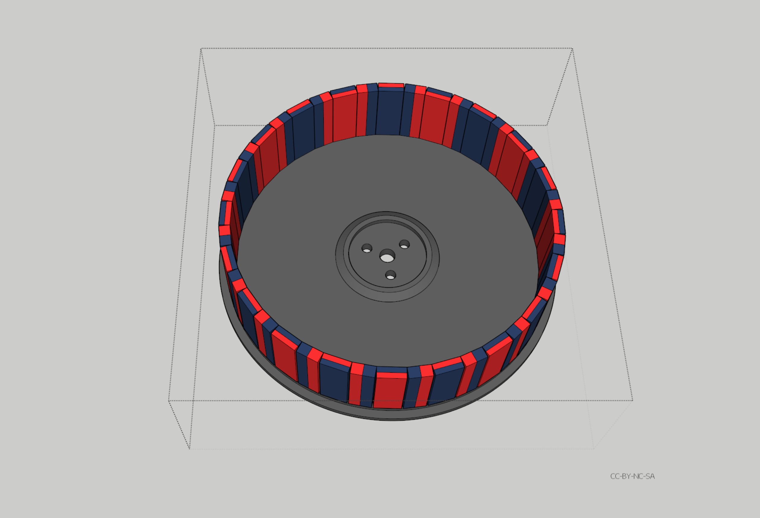
The original rotor weight was 926g after removing the inside cap, tire, and bearing. My volume and weight calculations said the magnets are about 233g, and the rest would be 474g if it were all aluminum, so the iron ring must be 336g, versus 117g for the equivalent volume of aluminum. From that I deduced that it should be 4mm thick, but it turned out to actually be 4.5mm due to that stepped down portion.
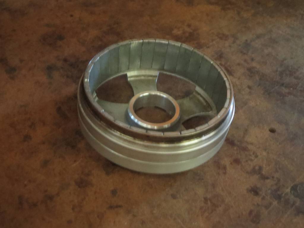
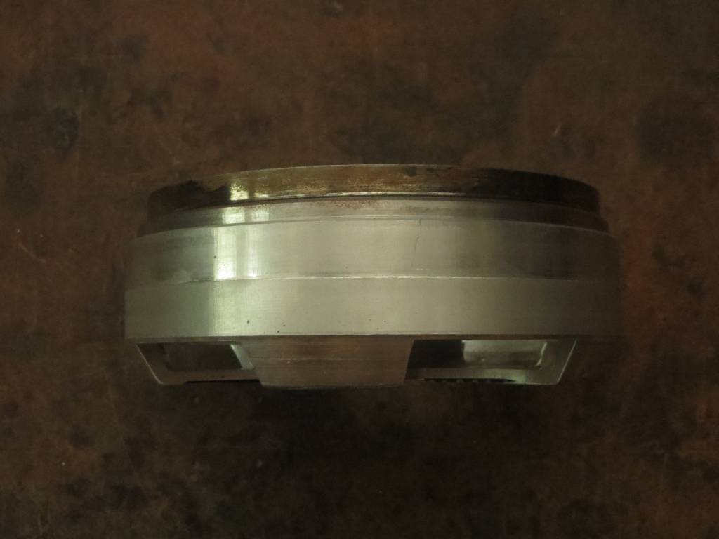
The final result is down to 700g. In the side shot, you can see a crack in the aluminum that formed where one of the screw holes was. I had originally planned to use the magnets from it to make my own carbon rotor, but decided to try machining it first just to see if I could. So if it does fall apart eventually, I will simply proceed with the original plan.
Next up is machining the shaft support arms out of the center of the stator so I can stick it on a traditional bearing tube mount. But I keep getting conflicting measurements on whether I have the stator perfectly level on the mill bed, so I haven’t had the guts to start cutting yet.
That’s not to bad for the iron. I suppose it does add some strength to the hover_wheel as well. Interesting project machining and converting that rotor. What is the use_case?
Ultimately the choice between zero iron and hallbach vs iron and stronger individual permanent magnets comes down to weight, but if a fully iron (tube) rotor has higher torque to equal out the more dense mass, I suppose it must come down to a stand-off. Naturally the aluminum wins the corrosion contest.
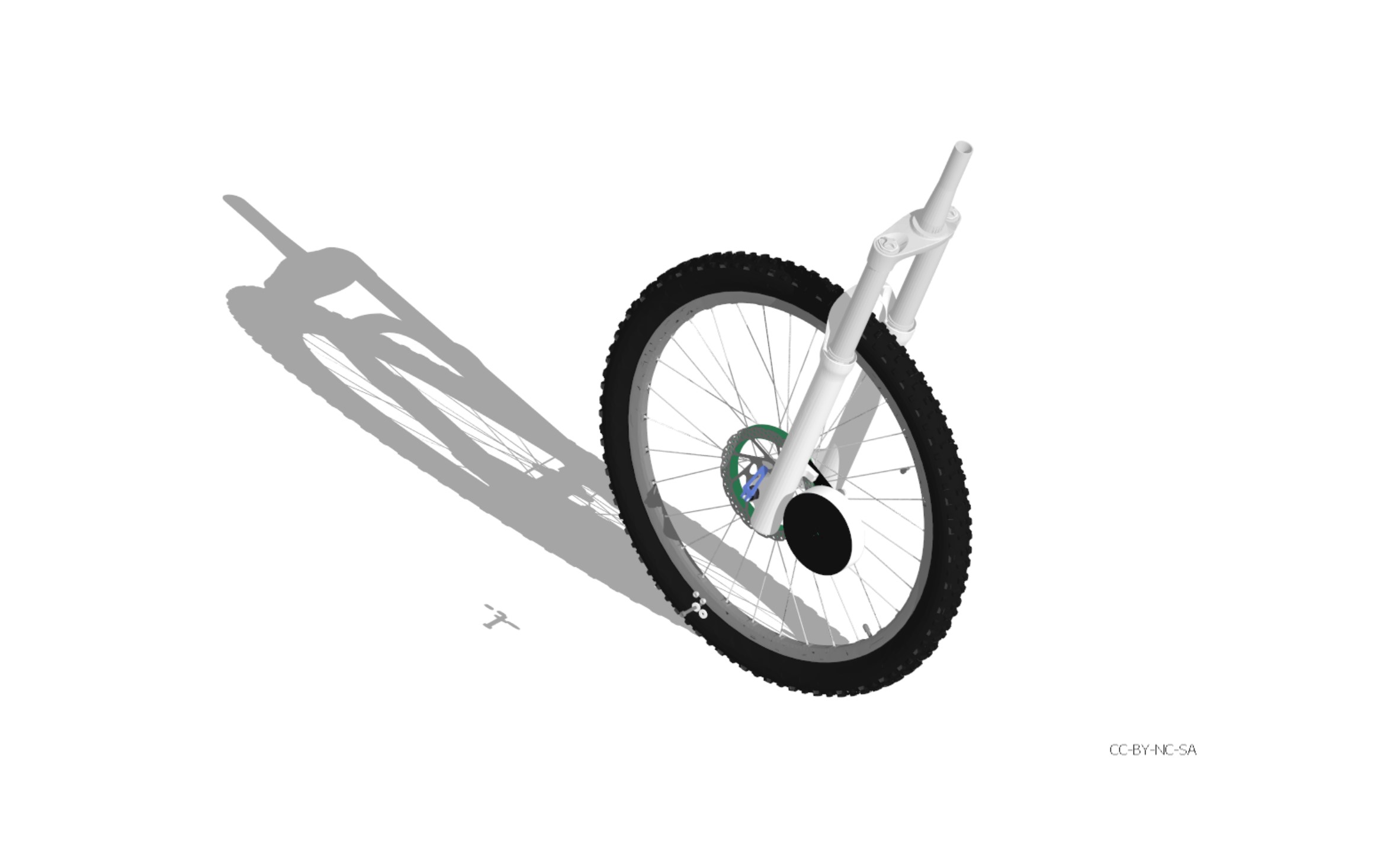
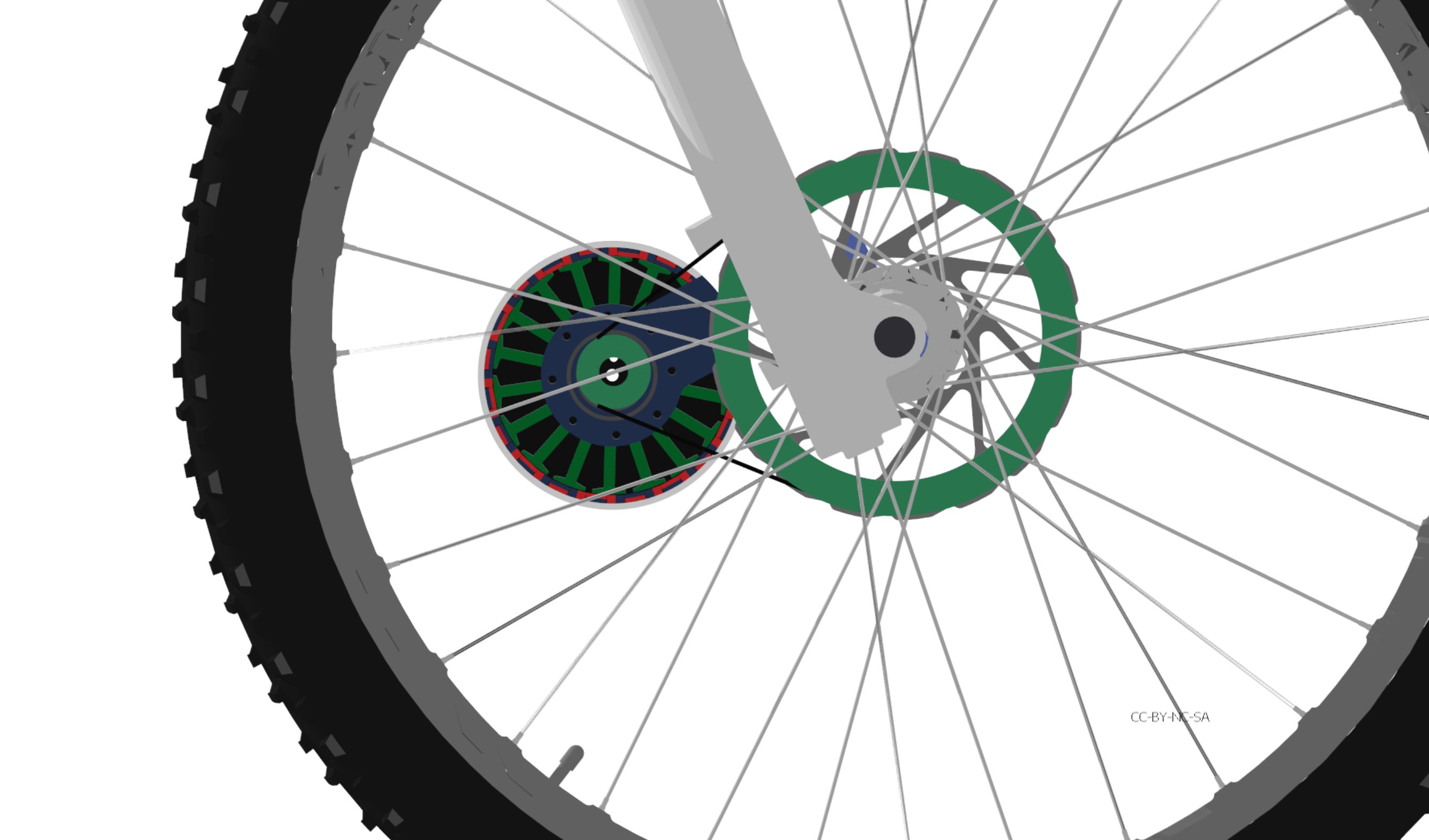
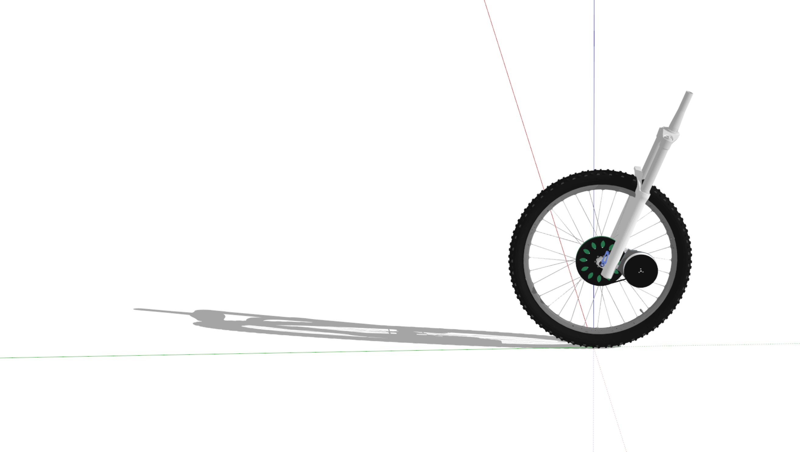
My reason for wanting to use a “small” (115mm stator) BLDC on a geared direct belt driven eMTB is obviously to cut down weight/mass and to achieve high torque at reasonable low current draw (to stay within the EU 45kmh ebike class, which has a 1000 watt limit, 19,2 amp at 52v). I believe it can hit a sweet spot between the bulky hub-motor and too power hungry 63mm outrunner. The upside to direct drive is the potential for a kinda ABS front brake, which will require a bunch of torque.
Looking forward to see your project in action!
I never did get an answer to my question in that rcgroups thread, whether halbach needs more magnet mass to make up for the missing back iron mass, or equal magnet mass and the back iron mass is simply eliminated.
I did notice that rust in the side photo of my hoverboard rotor, and gave it a coat of shellac afterward ![]() Hopefully that will keep the corrosion at bay.
Hopefully that will keep the corrosion at bay.
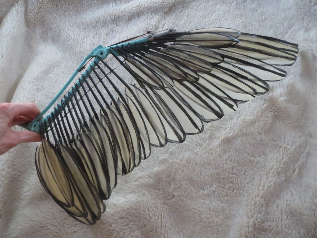
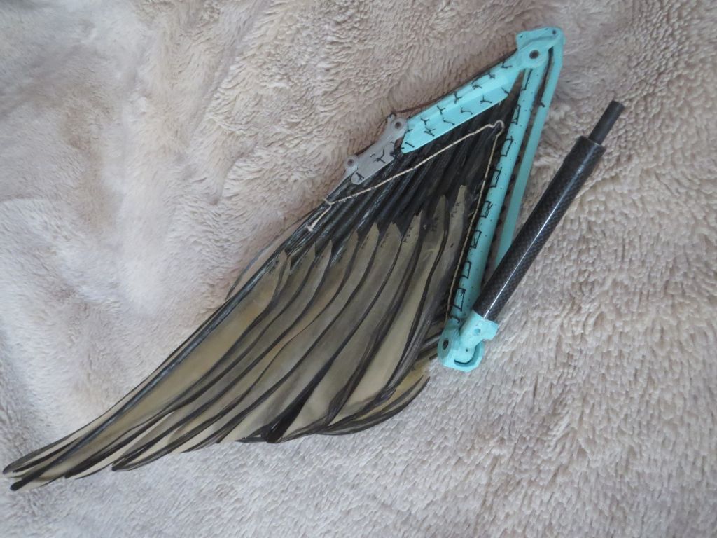
What it will be used for is a ridiculously powerful servo for flapping giant ornithopter wings. I’m getting ahead of myself messing with a large motor like this, as my actual project at the moment is a miniature version using a 2814 motor for the same role. Miniature will be 1.5m wingspan, hoverboard motor will be 4.3m, and if that works, human-carrying size should be 6.3m span. My avatar pic is a carbon/fiberglass feather scaled for that, about 4 feet long including the quill. Modeled from Canada goose, which is a good shape for human flight, but for the radio controlled ones I’ll be changing to American robin because geese have a zillion feathers and it’s a pain stringing them all up again and again for prototyping.
I think hoverboard motor would be good for 1000 watt limit at 1500RPM. You may not make it quite that high under load with 52V and the stock winding converted to delta, but it should be pretty close, and should have plenty of torque. I think they’re designed for around 5Nm continuous with the terrible cooling you get with a tire and fully enclosed stator and minimal airflow. 19.2Ax19.2Ax0.15ohms=55W waste heat to dissipate. Or perhaps 80W if that’s 19.2A on the battery side, since 1000W mechanical power should be 6.37Nm@1500RPM, and that works out to around 23A in the motor coils. I’m hoping to push it up to 15Nm intermittent, since it will have very good cooling in my case. That’s 450W waste heat ![]()
I truly hope you will get your wings, just remember to bring a shoot.
Like I clearly documented, the 18 pole can hold more turns of wire and will achieve higher torque. Maybe 45 turns is optimistic, but 37 turns will also surpass what’s possible on a 27 pole stator. Naturally, increasing the 27pole stator size will make it possible to hold more copper turns, but a 115mm 27pole is not optimal. It is made for one thing, to cheap out on copper. Winding the 18pole stator for use on a 250 watt “regular” bike class would also be interesting, lowering the Kv for 25kmh top speed and thereby increasing torque further (per watt). I know inductance will increase and could be a concern because of hefty voltage spikes when cutting power. The controller therefore must be immune to otherwise destructive transients. Asking a RCforum or eBoard on motor power usage, I’m sure they will say 100amps is nada, that’s probably why they put those 250w and 1000w limits in place. The idea is to include range into the equation.

I know you mean parachute, but here in America, the gun kind of shooting will actually be a significant danger if someone mistakes me for a live thunderbird ![]()
I was going to say that more torque is irrelevant if you’re not allowed to use it, but now that I think about it, that 6.37Nm limit probably only comes into play when you’re at 1500RPM. It depends on exactly how the regulation is worded. 19.2A from the battery is 1000W regardless of RPM, so at low speed your torque would only be limited by what the motor and power transistors can handle. 60RPM could theoretically use up to 159Nm ![]() Hundreds of Amps circulating in the motor coils.
Hundreds of Amps circulating in the motor coils.
I thought it was for hunting ![]()
Oh, hundreds of amps in my coils will most likely make a significant spark ![]() if power is cut abruptly. Hmm… all I’m saying is, my very attuned intuition is leaning toward higher inductance, more turns.
if power is cut abruptly. Hmm… all I’m saying is, my very attuned intuition is leaning toward higher inductance, more turns.
It depends on exactly how the regulation is worded.
I think it’s meant as continuous. So intermittent boost power is most likely probably allowed. That’s why I want a boost button on the handlebar with a boost gauge.
has a maximum continuous rated power which does not exceed 250 watts;”; and
Regulation (EU) No 168/2013 defines “maximum continuous rated power” as the maximum thirty minutes power at the
output shaft of an electric engine as set out in United Nations Economic Commission for Europe (UNECE) regulation No 85.

Right, 250 nominal and 650 peak’ish that’s in the ballpark. The 45kmh class bike need type approval from a certified lab (big bucks). So the most viable route is to rate the motor for 250 nominal, and let people compile the hex file. I remember back in the days, the cops tested mopeds on a portable dyno. Don’t think they will pull over or even measure the speed, let alone shaft wattage output over 30min on a ebike.
Taking into account, that the controller and motor also should be able to work on 36v I believe the 20-30amp mark is good for current sensing. With 16bit ADC resolution, it will have great resolution even in the lower end.
Here are some interesting observations on hallbach arrays:
Note that in the halbach arrangement, not only is the overall field stronger, but the stronger parts of the field are moved closer to center pole face where they are more useful to a rotating machine.
It would seem there are conflicting results from the modeling approach.
The presented study includes the design, analysis, and experimental work of a sub-fractional slot-concentrated winding BLDC motor with higher winding inductance.
Wow! Field weakening is freaking awesome. It’s like the best of both worlds, high torque when running slow, high speed if needed at the cost of torque, essentially extending the Kv rating of any given motor, which wouldn’t make sense for a low inductance motor, since it already has the speed but lag the torque. But for a high inductance motor, where back-emf limits the speed, it could make a real difference. Bringing this into the equation can enhance the overall performance of a light-EV. Or put in other words: implementing this into a geared direct drive setup, means we can increase the gear-ratio, gaining effective torque while hitting the same target speed. Upup and away!
https://community.simplefoc.com/t/zero-electrical-angle-tuning-and-max-speed/798

Increasing the battery voltage is better than field weakening, but it certainly is a useful alternative if you don’t have that option.
There’s an even better technique for IPM motors, shifting the current vector to boost speed while gaining additional reluctance torque as well. Almost doubles the maximum power compared to simple q-axis FOC. MTPA merged into VESC! | Details | Hackaday.io
Ok, that is impressive but those guys are working on huge (up to 800amp) motors. How are these equations relevant for a outrunner. Will it make the IPM (Inner permanent magnet) motor on par with a similar sized outrunner ?
I agree with regards to raising voltage, but I’m already planing for 14cells (51.8v nominal) and will most likely not up the voltage from there. In my opinion 14cell is plenty fine for a eMTB and will provide a safe margin for TVS diodes working with 100v FETs. In this scenario, with a high inductance motor, speed limited by b-emf, field weakening is a handy phenomenon.
If we are going to order custom magnets, then we might as well make them fit exactly how they should. Looking up how they produce neodymium magnets. You will find that they stack them up on a large grinding surface in order to shape them, as part of the process. If making chamfered edges, the magnets will most likely become more expensive. I found the 20pole 18slot to have the best winding factor (0.945), well actually 16poles 18 slots has the same winding factor, but smaller magnets makes a better circle, if they are square.
It’s not really relevant, just interesting, and came to mind when you mentioned field weakening. I don’t think anyone is making small IPM motors (although it would be fun to try it). As far as I know, the torque to weight ratio is still lower than outrunner, but power to weight ratio is higher due to the high speed. And better efficiency over a wider speed range, which is good for electric cars.
For custom magnets, someone in that rcgroups thread I linked before had a good idea to include a step at the ends so you can have mechanical retaining lips at the top and bottom without encroaching into the air gap or having to increase the magnet length. The bottom lip would also protect the fragile edge if you order them without chamfer.
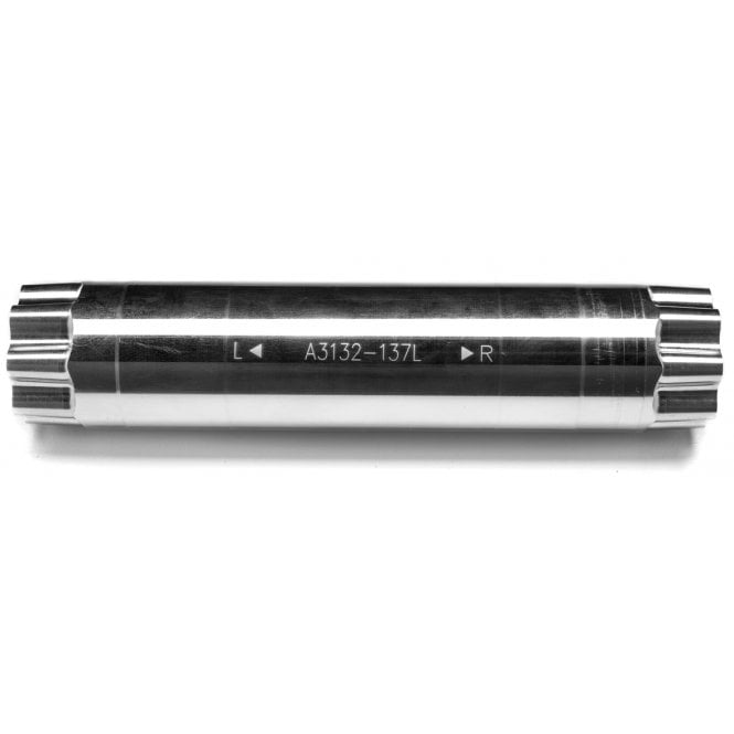
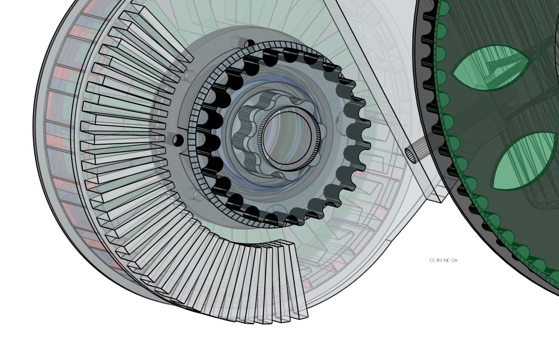
I’m thinking to mount a retaining ring after the stator is inserted. The magnets will have a edge in the rotor lid to grab on to. The retainer should be bonded with some kind of hard silicone. It should be possible to pry it off if necessary, but it must stay in place when turning. In theory it could be machined carbon fiber, which is quite stiff. Why not through in a large diameter bearing, that would stiffen the whole thing. I have decided to use a BB30 spindle, cut to length, as the shaft. Its 30mm Ø and hollow. Plus it´s made for MTBikes.

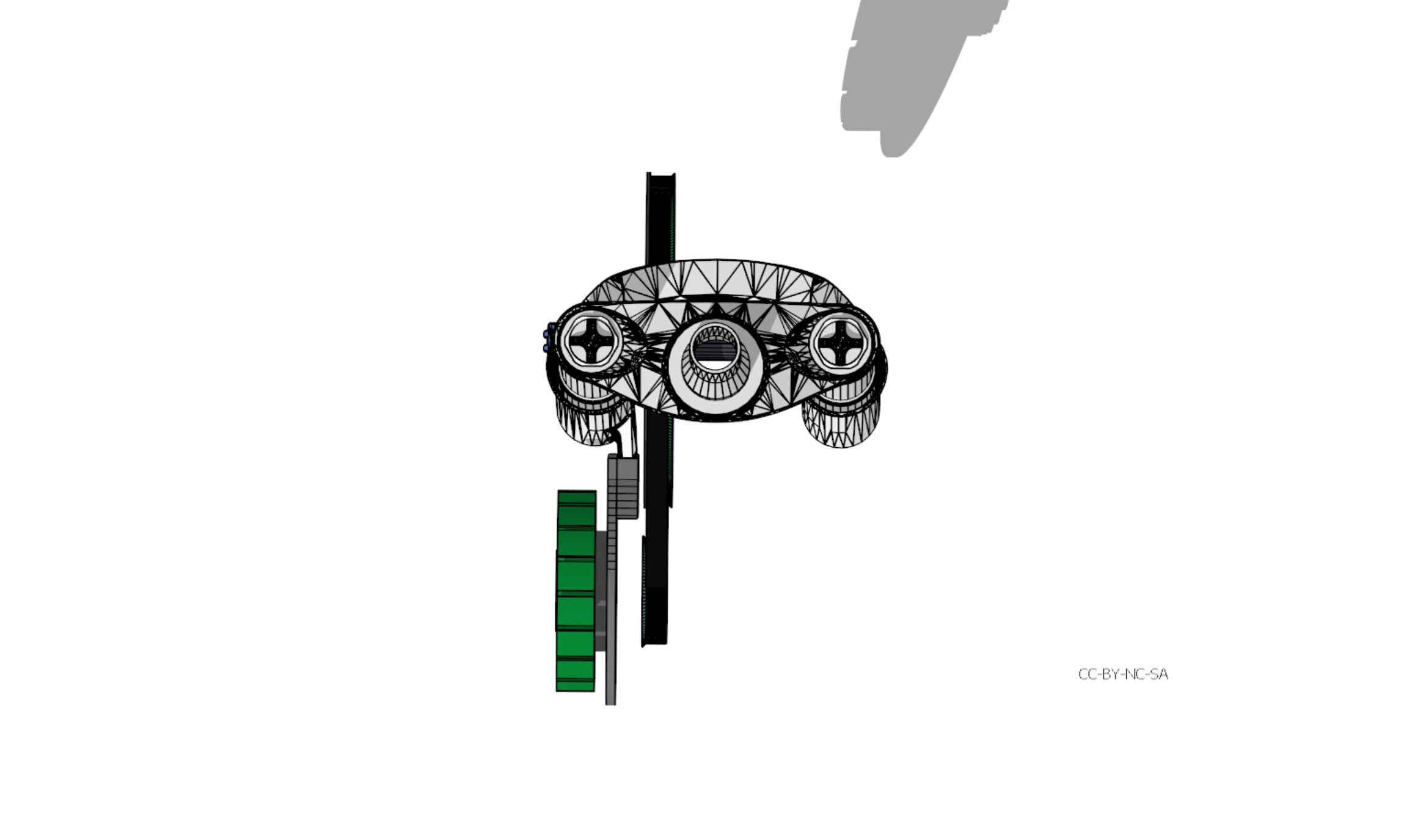
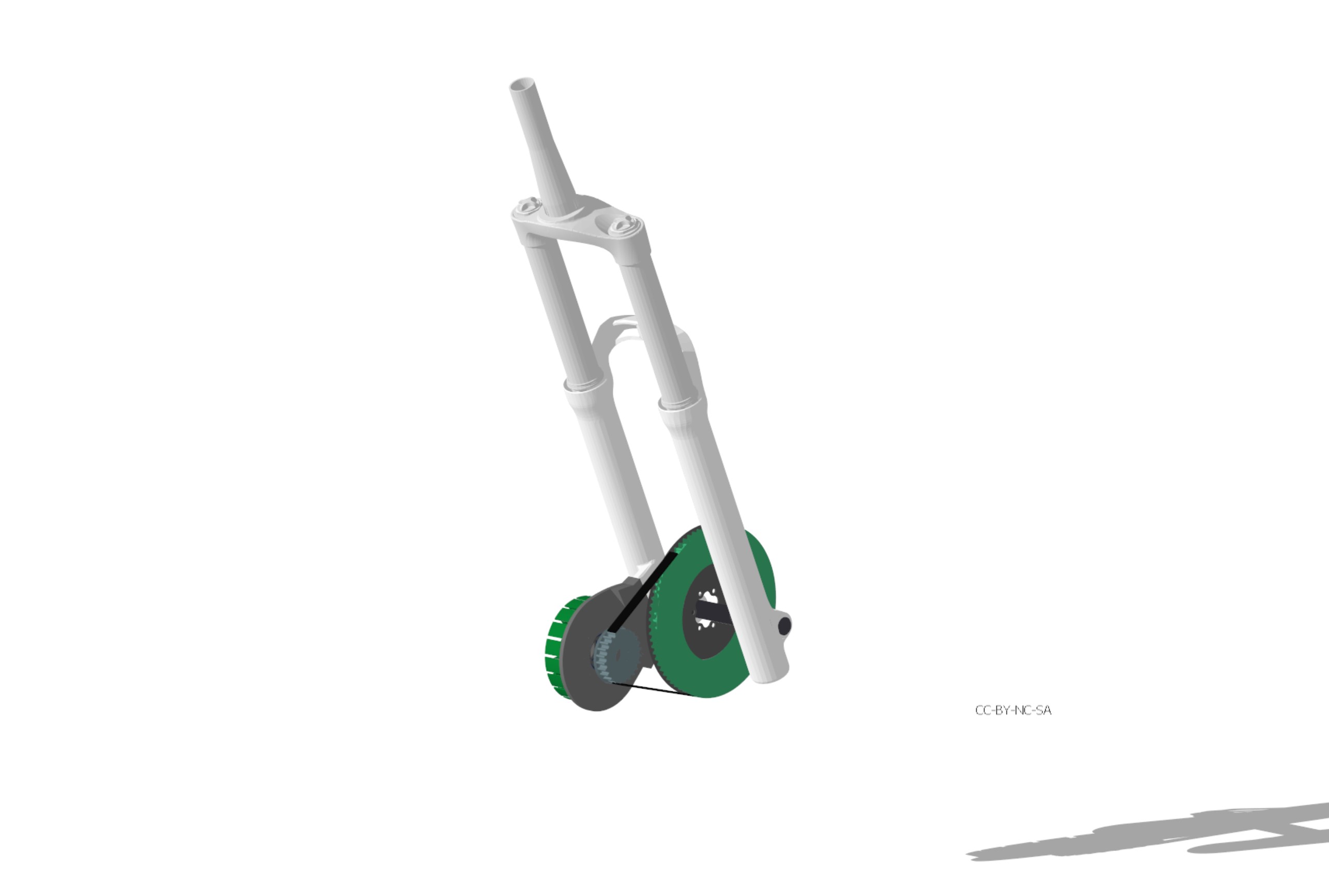
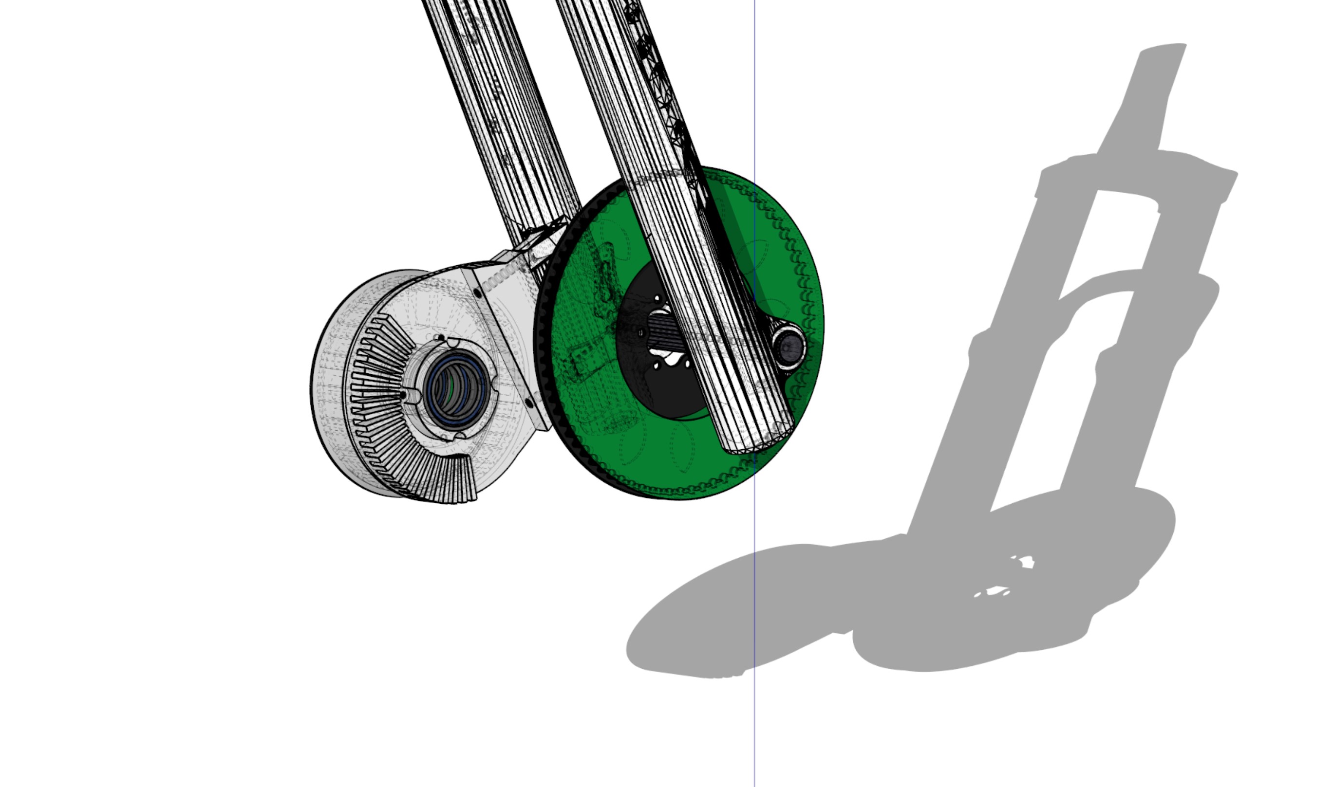
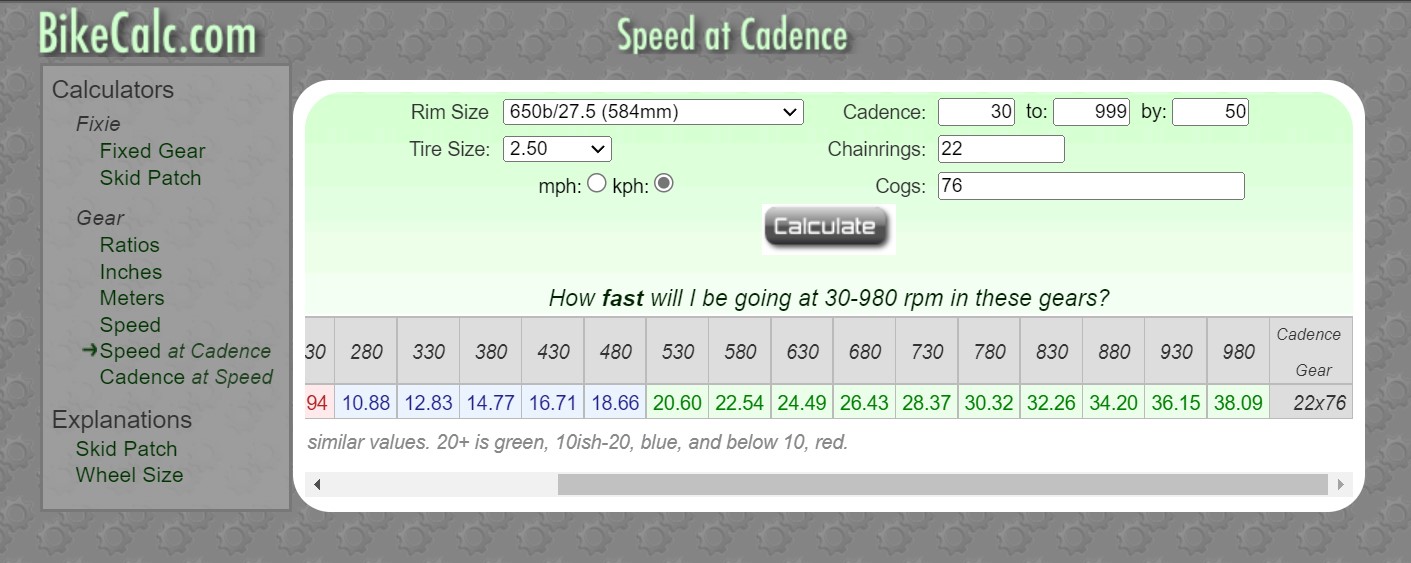
This is 74 teeth on the large gear and 24 teeth on the sprocket. Gearing will be 74/24 = 3.083. The belt I have is quite tuff, its a 8mm pitch delta chain, so I want it to have a perfect fit when the wheel is mounted.
Having 24 teeth on the sprocket gives a good tooth mesh.
The stator mounting plate / front fork mount, should be machined from a single peace of aluminum, which will be a good heatsink for the stator and windings.
How much of a decrease in rpm, can we expect from no load to bike load ?
I guess you can imagine how much force is needed, if you had 24 teeth on your crank and 74 teeth on your cassette… Only you cant peddle that fast ![]()
We can actually put small cooling fans on the 24t sprocket. And since the stator mount is machined, we can have some relatively large cooling fins machined out. A third bearing is also possible if machining.
@dekutree64 What is the smallest wall thickness you can machine aluminum ?