Hi, I make mi own PCB with atmega328pb, as5600 and L6234D.
I tried to make a BLDC tester.
When I try the angle read with the as5600 it’s all perfect, the as5600 reads the angle well.
But when I try with codes that supposed to move the BLDC motor, I don’t have the same results, the motor doesn’t move it just vibrates a little or makes a little noise. As well I try to move the position or the speed with a potentiometer, but it didn’t work either.
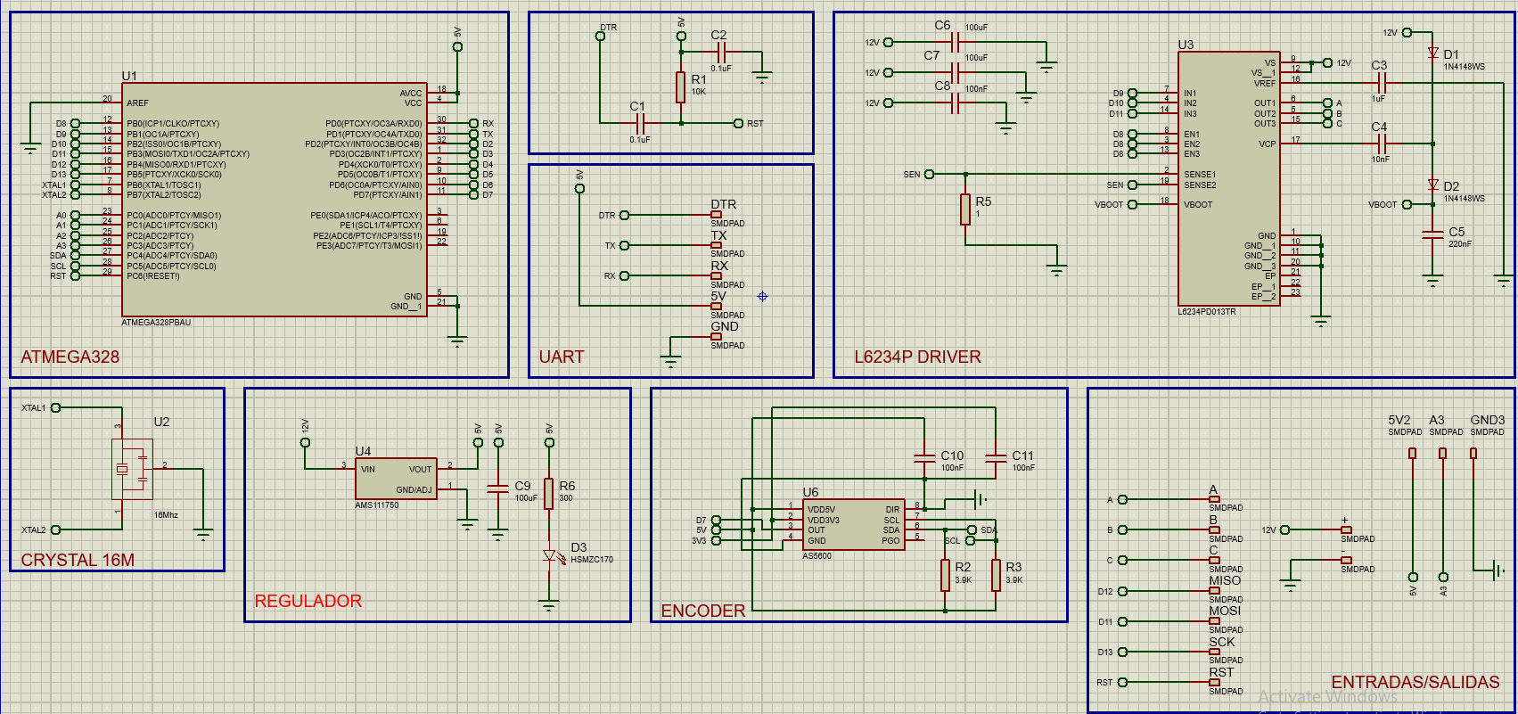
I share my schematic, and the code that supposed to developed for this PCB:
That is my code:
/********************************************************************************************************
 *  Title: ELECTRONOOBS open source FOC controller.
 * Date: 25/05/2024
 * Version: 2.5
 * Author: http://electronoobs.com
 * Based on tutorial: https://www.electronoobs.com/eng_arduino_tut198.php

 * This is a sensored ESC with FOC implemented based on Arduino with the ATmega328 chip.
 * It uses SPWM signals and PID to control the position of brushless motors.
 * Subscribe: https://youtu.be/pzGRKyHlXsM
********************************************************************************************************/

#include <Wire.h>
#include <AS5600.h>
#ifdef ARDUINO_SAMD_VARIANT_COMPLIANCE
  #define SERIAL SerialUSB
  #define SYS_VOL   3.3
#else
  #define SERIAL Serial
  #define SYS_VOL   5
#endif

//Variables for the hall effect angle sensor
AMS_5600 ams5600;
int ang, lang = 0;


//Inputs or outputs
const int potentiometer = A3;     // pot controls the RPM speed
const int MotorPinPhase_A =9;     //Driver's pin for coil A
const int MotorPinPhase_B =10;    //Driver's pin for coil B
const int MotorPinPhase_C =11;    //Driver's pin for coil C
const int buzzer = A2;            //Pin for the on board buzzer
const int fanPin = 5;             //Pin for fan MOSFET
const int supplyVoltagePin = A1;  //Pin for reading the supply voltage
const int temperaturePin = A0;    //Pin for reading the temperature with the NTC
const int PWMSensor = 2;          //PWM output from the magnetic encoder sensor (not used in this code...)

//The coils have a phase difference of 120 degrees so between each coil we have 120
//Here is where we will store the SPWM value for each coil
int SPWMValueA=0;
int SPWMValueB=120;
int SPWMValueC=240;


//Variables the user could change depending on teh used motor ...
const int motorPoles = 11;      //PP value is pole pair (S and N) of the motor. (22 magnets = 11 pp)
int TorqueValue=100;            //Set torque value from 0 to 100%;


/*The motor has ¡the real position in degrees from 0 to 360 but also the electrical position
 * The electrical position is affected by the amount of "pp" or pole pairs. In this case my motor
 * has 11 pairs, so for 360 degrees of real shaft rotation, we need 11 electrical rotations */
int RealShaftPosition=0;        //Here we store the read position of shaft from the sensor
int ElectricalPosition=0;       //Here we store the electrical position of shaft
int RotationDirection=0;        //Magnetic field orientation vector so we know if we rotate CW or CCW

//PID Variables
float PID_P = 0;                //Here we stopre the P gain
float PID_D = 0;                //Here we stopre the D gain
float Kp = 25;                  //P is the proportional gain for the PID control (no I yet...)
float Kd = 32;                  //D is the derivative gain for the PID control (no I yet...)
float PID_setpoint=0;           //Here we store the setpoint for the PID calculations
float PID_error=0;              //Here we store the error for the PID calculations (error = real_value - setpoint)
float previousPID_error=0;      //This is used for the D part of the PID calculations
float elapsedTime, currentTime, previousTime;        //Variables for time control
int PID_Torque=0;               //Here we will store the tortal PID torque affected by the PID code

void setup() {
  Serial.begin(115200);
  Wire.begin();

  TCCR1B = TCCR1B & 0b11111000 | 0x01;  // fix PWM frequency at 31250 Hz for Pins 9 and 10
  TCCR2B = TCCR2B & 0b11111000 | 0x01;  // fix PWM frequency at 31250 Hz for Pins 11 and 3
  ICR1 = 255 ;                          // 8 bit resolution

  pinMode(potentiometer, INPUT);        //Set pot pin as input
  pinMode(supplyVoltagePin, INPUT);     //Set voltage in pin as input
  pinMode(temperaturePin, INPUT);       //Set temperature read pin as input
  pinMode(MotorPinPhase_A, OUTPUT);     //Set driver pins as outputs
  pinMode(MotorPinPhase_B, OUTPUT);     //Set driver pins as outputs
  pinMode(MotorPinPhase_C, OUTPUT);     //Set driver pins as outputs
  pinMode(buzzer, OUTPUT);              //Set buzzer as output
  pinMode(fanPin, OUTPUT);              //Set fanPin as output

  digitalWrite(buzzer, LOW);            //Start with the buzzer off
  digitalWrite(fanPin, LOW);            //Start with the fan off (temperature not yet implemented)

  //Start the magnetic sensor and check for magnet...
  if(ams5600.detectMagnet() == 0 ){
    while(1){
      if(ams5600.detectMagnet() == 1 ){
        SERIAL.print("Current Magnitude: ");
        SERIAL.println(ams5600.getMagnitude());
        break;
      }
      else{
        SERIAL.println("Can not detect magnet");
      }
      delay(200);
    }
  }//End of setting the magnet sensor
  currentTime = millis();

  //tone(buzzer, 2000, 1000);
}//End of SETUP LOOP


void loop() {
  //Read the setpoint from the potentiometer
  PID_setpoint = analogRead(potentiometer);                             //Read the analog value of the potentiometer
  PID_setpoint = map(PID_setpoint,0,1023,0,360);                        //Map that value to a range of 0 to 360º

  //Read the real angle from the sensor
  float rawangle = ams5600.getRawAngle();                               //RAW read from the sensor (not in degrees yet)
  float realAngle = rawangle * 0.087890625;                             //Value from sensor datasheet
  realAngle = constrain(realAngle, 0, 360);                             //Constraint the values to a range of 0 to 360º

  ElectricalPosition=map(realAngle,0,360,0,(360*motorPoles));           //We need to scale the electrical position depending on the amount of pole pairs
  ElectricalPosition=constrain(ElectricalPosition, 0, 360*motorPoles);  //Constraint the values once again
  RealShaftPosition=map(ElectricalPosition,0,(360*motorPoles),0,360);

  // We first calculate the PID error between the value we want and the value we have (in degrees)
  PID_error=RealShaftPosition-PID_setpoint;                             //First as always, wec alculate teh PID error

  //Decide if we go CW or CCW
  if (PID_error<0){RotationDirection = 90;}                             //Magnetic field vector is now 90 degrees ahead so CW
  if (PID_error>0){RotationDirection = 270;}                            //Magnetic field vector is now 90 degrees behind so CCW


  ////////////PID Calculations///////////////
  //Calculate the P gain
  PID_P = Kp * PID_error;

  //Calculate the D gain
  currentTime = millis();
  elapsedTime = currentTime - previousTime;
  PID_D = Kd*((PID_error - previousPID_error)/elapsedTime);
  previousTime = currentTime;
  previousPID_error = PID_error;

  //Sum up P and D gains
  PID_Torque=abs(PID_P + PID_D);                                      //Define the gain of the PID system.
  PID_Torque=constrain(PID_Torque,0,TorqueValue);                     //Limit the torque 0-100%. The driver might get HOT so lower the value to maybe 50% or so...

  rotate();   //Run the function that will apply the SPWM values to the driver

}//End of VOID LOOP


void rotate(){
  const int SyncOffset=21;                                              //You might neet do adjust this value (offset between where the real angle starts and the electrical angle starts)
  SPWMValueA = ElectricalPosition + RotationDirection + SyncOffset;     //We add the position and direction so it will rotate CW or CW
  SPWMValueB = SPWMValueA + 120;                                        //120 degrees of phase difference between coils A and B
  SPWMValueC = SPWMValueB + 120;                                        //120 degrees of phase difference between coils B and C

  SPWMValueA = SPWMValueA%360;                                          //Keep the values between 0 and 360 degrees
  SPWMValueB = SPWMValueB%360;
  SPWMValueC = SPWMValueC%360;


  //Calculate the PWM values for creating a sine signal (SPWM)
  int SINE_A_PWM = sin((double)SPWMValueA*PI/360)*127.5+127.5;          //Multiply by PI and divide by 180 in order to pass from degrees to radians
  int SINE_B_PWM = sin((double)SPWMValueB*PI/360)*127.5+127.5;          //Multiply by 127.5 and add 127.5 in order to keep the range between 0-255 (8 bit PWM signal)
  int SINE_C_PWM = sin((double)SPWMValueC*PI/360)*127.5+127.5;          //SINE values between -1 and 1 are placed between 0-255 for PWM.


  //Write SPWM values to each pin of the driver
  analogWrite(MotorPinPhase_A, SINE_A_PWM*PID_Torque/100);
  analogWrite(MotorPinPhase_B, SINE_B_PWM*PID_Torque/100);
  analogWrite(MotorPinPhase_C, SINE_C_PWM*PID_Torque/100);

}//End of moving function
Try open loop velocity first, to make sure PWM is working properly. Something like
loop() {
  PID_Torque = 20;
  ElectricalPosition++;
  rotate();
  delay(1);
}
Assuming you’re using a 7 pole pair motor, that should rotate around 32RPM. PID_Torque = 20 is just a guess, set it higher or lower if needed.
I use a 12 pole pair motor, the part of the code that you give me (I’m new in this FOC stuff) Do I need to replace everything in the code loop that I shared?
Yeah, this is just a test without all the PID code, to narrow down where the problem is. If it rotates slowly, the problem is in the PID code. If it doesn’t move, the problem is in the PWM code.
Ok, thanks for your answer I’ll try this tomorrow and post the results
Hi, I replace the loop code by the code that you give me, at first, the motor doesn’t move or vibrates, but I change the PID_Torque to 100, and the motor begins to vibrate a little, I change one more time to 10000 and the motor vibrate a little more but it still doesn’t move.
I let the code that I upload to atmega328pb with the changes:
#include <Wire.h>
#include <AS5600.h>
#ifdef ARDUINO_SAMD_VARIANT_COMPLIANCE
  #define SERIAL SerialUSB
  #define SYS_VOL   3.3
#else
  #define SERIAL Serial
  #define SYS_VOL   5
#endif

//Variables for the hall effect angle sensor
AMS_5600 ams5600;
int ang, lang = 0;


//Inputs or outputs
const int potentiometer = A3;     // pot controls the RPM speed
const int MotorPinPhase_A =9;     //Driver's pin for coil A
const int MotorPinPhase_B =10;    //Driver's pin for coil B
const int MotorPinPhase_C =11;    //Driver's pin for coil C
const int supplyVoltagePin = A1;  //Pin for reading the supply voltage
const int temperaturePin = A0;    //Pin for reading the temperature with the NTC
const int PWMSensor = 2;          //PWM output from the magnetic encoder sensor (not used in this code...)

//The coils have a phase difference of 120 degrees so between each coil we have 120
//Here is where we will store the SPWM value for each coil
int SPWMValueA=0;
int SPWMValueB=120;
int SPWMValueC=240;


//Variables the user could change depending on teh used motor ...
const int motorPoles = 12;      //PP value is pole pair (S and N) of the motor. (22 magnets = 11 pp)
int TorqueValue=100;            //Set torque value from 0 to 100%;


/*The motor has ¡the real position in degrees from 0 to 360 but also the electrical position
 * The electrical position is affected by the amount of "pp" or pole pairs. In this case my motor
 * has 11 pairs, so for 360 degrees of real shaft rotation, we need 11 electrical rotations */
int RealShaftPosition=0;        //Here we store the read position of shaft from the sensor
int ElectricalPosition=0;       //Here we store the electrical position of shaft
int RotationDirection=0;        //Magnetic field orientation vector so we know if we rotate CW or CCW

//PID Variables
float PID_P = 0;                //Here we stopre the P gain
float PID_D = 0;                //Here we stopre the D gain
float Kp = 25;                  //P is the proportional gain for the PID control (no I yet...)
float Kd = 32;                  //D is the derivative gain for the PID control (no I yet...)
float PID_setpoint=0;           //Here we store the setpoint for the PID calculations
float PID_error=0;              //Here we store the error for the PID calculations (error = real_value - setpoint)
float previousPID_error=0;      //This is used for the D part of the PID calculations
float elapsedTime, currentTime, previousTime;        //Variables for time control
int PID_Torque=0;               //Here we will store the tortal PID torque affected by the PID code

void setup() {
  Serial.begin(115200);
  Wire.begin();

  TCCR1B = TCCR1B & 0b11111000 | 0x01;  // fix PWM frequency at 31250 Hz for Pins 9 and 10
  TCCR2B = TCCR2B & 0b11111000 | 0x01;  // fix PWM frequency at 31250 Hz for Pins 11 and 3
  ICR1 = 255 ;                          // 8 bit resolution

  pinMode(potentiometer, INPUT);        //Set pot pin as input
  pinMode(supplyVoltagePin, INPUT);     //Set voltage in pin as input
  pinMode(temperaturePin, INPUT);       //Set temperature read pin as input
  pinMode(MotorPinPhase_A, OUTPUT);     //Set driver pins as outputs
  pinMode(MotorPinPhase_B, OUTPUT);     //Set driver pins as outputs
  pinMode(MotorPinPhase_C, OUTPUT);     //Set driver pins as outputs
            //Set fanPin as output

  //Start the magnetic sensor and check for magnet...
  if(ams5600.detectMagnet() == 0 ){
    while(1){
      if(ams5600.detectMagnet() == 1 ){
        SERIAL.print("Current Magnitude: ");
        SERIAL.println(ams5600.getMagnitude());
        break;
      }
      else{
        SERIAL.println("Can not detect magnet");
      }
      delay(200);
    }
  }//End of setting the magnet sensor
  currentTime = millis();

  //tone(buzzer, 2000, 1000);
}//End of SETUP LOOP


void loop() {
  PID_Torque = 10000;
  ElectricalPosition++;
  rotate();
  delay(1);
}//End of VOID LOOP


void rotate(){
  const int SyncOffset=21;                                              //You might neet do adjust this value (offset between where the real angle starts and the electrical angle starts)
  SPWMValueA = ElectricalPosition + RotationDirection + SyncOffset;     //We add the position and direction so it will rotate CW or CW
  SPWMValueB = SPWMValueA + 120;                                        //120 degrees of phase difference between coils A and B
  SPWMValueC = SPWMValueB + 120;                                        //120 degrees of phase difference between coils B and C

  SPWMValueA = SPWMValueA%360;                                          //Keep the values between 0 and 360 degrees
  SPWMValueB = SPWMValueB%360;
  SPWMValueC = SPWMValueC%360;


  //Calculate the PWM values for creating a sine signal (SPWM)
  int SINE_A_PWM = sin((double)SPWMValueA*PI/360)*127.5+127.5;          //Multiply by PI and divide by 180 in order to pass from degrees to radians
  int SINE_B_PWM = sin((double)SPWMValueB*PI/360)*127.5+127.5;          //Multiply by 127.5 and add 127.5 in order to keep the range between 0-255 (8 bit PWM signal)
  int SINE_C_PWM = sin((double)SPWMValueC*PI/360)*127.5+127.5;          //SINE values between -1 and 1 are placed between 0-255 for PWM.


  //Write SPWM values to each pin of the driver
  analogWrite(MotorPinPhase_A, SINE_A_PWM*PID_Torque/100);
  analogWrite(MotorPinPhase_B, SINE_B_PWM*PID_Torque/100);
  analogWrite(MotorPinPhase_C, SINE_C_PWM*PID_Torque/100);

}//End of moving function
I try with this code:
#include <SimpleFOC.h>

BLDCMotor motor = BLDCMotor(12);
BLDCDriver3PWM driver = BLDCDriver3PWM(9, 10, 11, 8);

float target_velocity = 0;

Commander command = Commander(Serial);
void doTarget(char* cmd) { command.scalar(&target_velocity, cmd); }
void doLimit(char* cmd) { command.scalar(&motor.voltage_limit, cmd); }

void setup() {
  driver.voltage_power_supply = 12;
  driver.voltage_limit = 6;
  driver.init();
  motor.linkDriver(&driver);

  motor.voltage_limit = 3;
  motor.controller = MotionControlType::velocity_openloop;

  motor.init();

  command.add('T', doTarget, "target velocity");
  command.add('L', doLimit, "voltage limit");

  Serial.begin(115200);
  Serial.println("Motor ready!");
  Serial.println("Set target velocity [rad/s]");
  _delay(1000);
}

void loop() {
  motor.move(target_velocity);
  command.run();
}
And the results are the same, the motor just vibrates a little, If I set higher values for the r/s the motor vibrates a little more but doesn’t move.
Hmm, so maybe a hardware problem then? Try using angle_openloop and measuring the voltages on the motor wires with a multimeter (one probe on ground, other on wire). Change the target angle and measure again a few times to see if they all change or if one is not working.
/**
 *
 * Position/angle motion control example
 * Steps:
 * 1) Configure the motor and magnetic sensor
 * 2) Run the code
 * 3) Set the target angle (in radians) from serial terminal
 *
 */
#include <SimpleFOC.h>

// magnetic sensor instance - SPI
MagneticSensorSPI sensor = MagneticSensorSPI(AS5147_SPI, 10);
// magnetic sensor instance - MagneticSensorI2C
//MagneticSensorI2C sensor = MagneticSensorI2C(AS5600_I2C);
// magnetic sensor instance - analog output
// MagneticSensorAnalog sensor = MagneticSensorAnalog(A1, 14, 1020);

// BLDC motor & driver instance
BLDCMotor motor = BLDCMotor(11);
BLDCDriver3PWM driver = BLDCDriver3PWM(9, 5, 6, 8);
// Stepper motor & driver instance
//StepperMotor motor = StepperMotor(50);
//StepperDriver4PWM driver = StepperDriver4PWM(9, 5, 10, 6,  8);

// angle set point variable
float target_angle = 0;
// instantiate the commander
Commander command = Commander(Serial);
void doTarget(char* cmd) { command.scalar(&target_angle, cmd); }

void setup() {

  // use monitoring with serial
  Serial.begin(115200);
  // enable more verbose output for debugging
  // comment out if not needed
  SimpleFOCDebug::enable(&Serial);

  // initialise magnetic sensor hardware
  sensor.init();
  // link the motor to the sensor
  motor.linkSensor(&sensor);

  // driver config
  // power supply voltage [V]
  driver.voltage_power_supply = 12;
  driver.init();
  // link the motor and the driver
  motor.linkDriver(&driver);

  // choose FOC modulation (optional)
  motor.foc_modulation = FOCModulationType::SpaceVectorPWM;

  // set motion control loop to be used
  motor.controller = MotionControlType::angle;

  // contoller configuration
  // default parameters in defaults.h

  // velocity PI controller parameters
  motor.PID_velocity.P = 0.2f;
  motor.PID_velocity.I = 20;
  motor.PID_velocity.D = 0;
  // maximal voltage to be set to the motor
  motor.voltage_limit = 6;

  // velocity low pass filtering time constant
  // the lower the less filtered
  motor.LPF_velocity.Tf = 0.01f;

  // angle P controller
  motor.P_angle.P = 20;
  // maximal velocity of the position control
  motor.velocity_limit = 20;

  // comment out if not needed
  motor.useMonitoring(Serial);


  // initialize motor
  motor.init();
  // align sensor and start FOC
  motor.initFOC();

  // add target command T
  command.add('T', doTarget, "target angle");

  Serial.println(F("Motor ready."));
  Serial.println(F("Set the target angle using serial terminal:"));
  _delay(1000);
}


void loop() {

  // main FOC algorithm function
  // the faster you run this function the better
  // Arduino UNO loop  ~1kHz
  // Bluepill loop ~10kHz
  motor.loopFOC();

  // Motion control function
  // velocity, position or voltage (defined in motor.controller)
  // this function can be run at much lower frequency than loopFOC() function
  // You can also use motor.move() and set the motor.target in the code
  motor.move(target_angle);


  // function intended to be used with serial plotter to monitor motor variables
  // significantly slowing the execution down!!!!
  // motor.monitor();

  // user communication
  command.run();
}
Is that the code? I dont found the anlge_loop
You can use your same code from before, just change velocity_openloop to angle_openloop.
Ok I did the measurings and the results are:
60° A=6v B=6v C=6v
180° A=5.8v B=5.76v C=5.8v
360° A=6.65v B=6.65v C=6.65v
0° A=6.24v B=6.23v C=6.23v
Is that correct?
I think it’s something related to the current, I supply voltage to the PCB with a PSU, I supply 12V 2A, but when I conect the PCB the current drops to 0.050A, and now that I’ve reconnected the PCB the current is 0.140A - 0.150A and the motor vibrates more, but I don’t know why is happening this.
It’s a strange problem. The phases should all be different (120 degrees apart sine waves), but instead they all change together.
Maybe by the motor model? It’s MN4006 KV380.
I tried connecting the L6234D to Arduino Uno and I have the same results so, I don’t know what is happening, Maybe something in the schematic, but I saw a lot of examples and the datasheets and the componentes and connections are the same
I just measured the voltage in the pins of the atmega328p, 9,10,11 and put the angle in 360°.
The results are:
9= 0.7v
10=2.48v
11=0.528v
If I measure without the motor in 360 degrees I have
A=1.67v
B=6.05v
C=1.252
In 0°
A= 2.9V
B= 5.63v
C=334mV
In180°
A=3.65v
B=0.44mv
C=5.23V
I tried with a 7 pair pole motor and when I put 0 degrees the motor moves but with a lot of vibrations and when I put other angle doesn’t move again
So the input pins to the driver are all different (good), but output pins are all the same (bad)? I don’t think that driver has overcurrent protection, so it may be internally burnt. The T-Motor web site lists that motor as 0.194 ohm resistance, so even 1 volt applied at 0 speed will quickly overheat, and anything more is likely to kill it. Try again with a new driver and motor.voltage_limit = 0.5 or less.
Higher voltage can be applied once the motor is moving, using the voltage-based current limiting. But for initial testing, keep it in a condition that is guaranteed safe.
I just tried again with voltage limit and other driver, and I have the same results, so I don’t know what is happen