If someone have the same problem, I found the solution!.
Trying a lot of codes and measuring voltages, the problem is in the R5, in my schematic the resistor connected to SEN1 and SEN2 to GND, I just removed and connect SEN1 and SEN2 to GND, and my motor is now spinning.
But I have other problem, my motor doesn’t spin if I don’t give it a “push”.
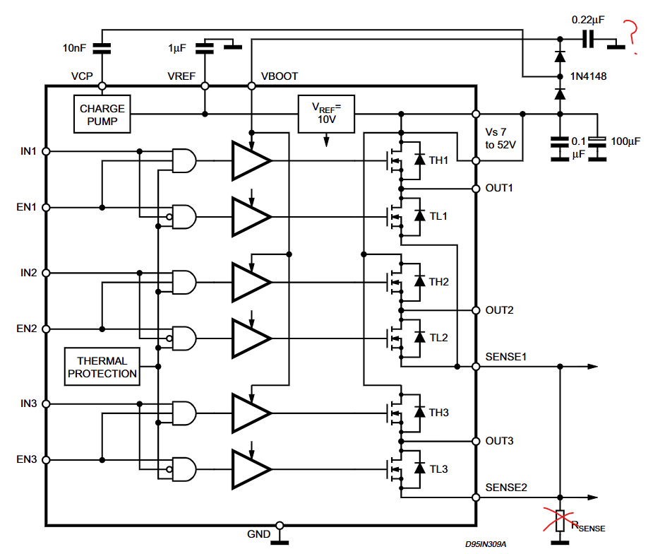
Excellent! Glad you figured it out. I thought those sense pins were just an optional output for the microcontroller to monitor, but looking at the datasheet diagram more closely, they are the high power ground pins of the mosfets. I also thought the resistor in your schematic was 1 ohm, not 1k. That makes sense why it would choke the output of two phases, causing their output voltage to follow the one that was not limited.
On the bright side, that means the other chip is not burnt.
To properly use those pins, you’d connect resistors of a few milliohms so they don’t waste much power, and measure the small voltage drop across them. But the drop is too small for ATmega to read directly, so you need amplifiers. Plus I’m not sure how you sort out the currents from the first two phases when they’re mixed together like that.
Maybe just the nature of open loop. If you ramp up the speed it will probably follow. 3V is fine once the motor is moving since the back EMF cancels the applied voltage to keep the current low, but be careful since the driver might burn if the motor is stalled.
It’s working well enough, so move on to closed loop now. Set motor.voltage_sensor_align to 1 or less, and motor.voltage_limit to 0.5 again. If it fails to move during calibration when you call motor.init_foc(), then maybe this motor’s resistance is higher than the spec sheet I found and it really does need more voltage to get going. But always best to start low and see if anything gets hot before increasing voltage.
After you have it turning slowly in closed loop, you can add the voltage-based current limiting to reach higher speed safely.
Huh, reading back through the posts I don’t know why I thought you said it was 1k. 1 ohm wouldn’t choke it entirely, but I guess still enough to prevent it from moving.
Voltage-based current limiting uses the measured rotor speed to estimate the back-EMF, and applies higher voltage to counteract it. It’s activated by setting motor.phase_resistance and motor.KV_rating. Start with the official specs for your motor, but it will probably need some finetuning.
It’s less reliable than actual current sense, but works well when the motor is running smoothly. In my experience, rapid oscillation from bad PID tuning is what throws it off the most. The measured speed is higher than the real back EMF, resulting in higher than expected current. I’ve burnt two drivers that way, so keep voltage limit <=1V while tuning PID.
Sounds like it probably does just need more voltage then. We’ll just have to experimentally find out how much it can take.
Comment out the calls to motor.move and motor.loopFOC, and instead call driver.setPhaseVoltage(target, 0, 0); This bypasses all the motor limits, and won’t move the motor since we’re commanding electrical angle 0 every time, but will run current through it.
Gradually ramp up the target while monitoring the temperature to see when the motor or driver gets hot. Start with 0.5 and let it run for 10-20 seconds. If it’s still cool, try 1 and wait another 10-20 seconds. Keep going in 1 volt steps until something gets uncomfortably hot, and then reduce it until you find where it reaches equilibrium at a reasonable temperature.
C:\Users\digis\AppData\Local\Temp.arduinoIDE-unsaved202546-13884-71zua8.ppvn\velocity_control\velocity_control.ino: In function ‘void loop()’:
C:\Users\digis\AppData\Local\Temp.arduinoIDE-unsaved202546-13884-71zua8.ppvn\velocity_control\velocity_control.ino:98:10: error: ‘class BLDCDriver3PWM’ has no member named ‘setPhaseVoltage’; did you mean ‘setPhaseState’?
driver.setPhaseVoltage(target, 0, 0);
^~~~~~~~~~~~~~~
setPhaseState
C:\Users\digis\AppData\Local\Temp.arduinoIDE-unsaved202546-13884-71zua8.ppvn\velocity_control\velocity_control.ino:98:26: error: ‘target’ was not declared in this scope
driver.setPhaseVoltage(target, 0, 0);
^~~~~~
C:\Users\digis\AppData\Local\Temp.arduinoIDE-unsaved202546-13884-71zua8.ppvn\velocity_control\velocity_control.ino:98:26: note: suggested alternative: ‘doTarget’
driver.setPhaseVoltage(target, 0, 0);
^~~~~~
doTarget
exit status 1
Compilation error: ‘class BLDCDriver3PWM’ has no member named ‘setPhaseVoltage’; did you mean ‘setPhaseState’?
Sorry, that should have been motor.setPhaseVoltage, not driver. And target is a variable you have to create yourself. Let me just write the program entirely to eliminate confusion…
And this is not closed-loop, it’s just an experiment to find the motor’s safe maximum voltage. As said before, start with 0.5 and let it run for 10-20 seconds. If the motor and driver are still cool, try 1 and wait another 10-20 seconds. Keep going in 1 volt steps until something gets uncomfortably hot, and then reduce it until you find where it reaches equilibrium at a reasonable temperature.
After that you can run the closed-loop velocity example here, after modifying with your motor/driver/sensor configuration, including the motor voltage limit. The PID will probably need tuning as well, so you could add some commands to change motor.PID_velocity.P and motor.PID_velocity.I while running.
I ran into the same problem with my custom board using the DRV8313 and STM32F103. The motor didn’t move at all until I realized the PWM pins were mapped wrong in my code. After fixing that and rechecking the motor phases, it worked right away.
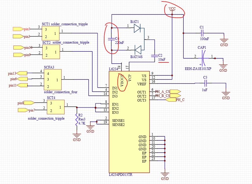
I connect VBOOT between D2 and C5, then the C5 is connected to GND.
I saw the official schematic of the SimpleFOC Shield V2.04 and these connections are:
VBOOT to C4 and C4 is between the diodes, then the first diode anode is connected to VCC.
Someone knows, If that is important and If this is the problem that I have?
I know that VBOOT and the BOOTSTRAP connection it’s important for the motor charge.
I faced a similar issue with my custom PCB using the AS5600 sensor and L6234 driver. Initially, the motor didn’t move at all. After increasing the PID_Torque value to 10000, the motor started to vibrate slightly but still didn’t rotate. It turned out that the problem was in the PWM code. Once I adjusted the PWM settings, the motor began to spin as expected. Hope this helps!
I figure out this!
If someone have this problem in the future, I explain the solution:
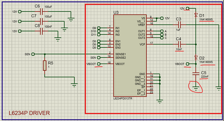
I buyed a L6234D in JLCPCB, I check the datasheet and the schematic is:
First of all, the Rsense give me the problem that the motor doesn’t spin, so I remove the resistor and connect direct to GND.
Then my motor doesn’t spin smooth and I need to “help” with my fingers to spin.
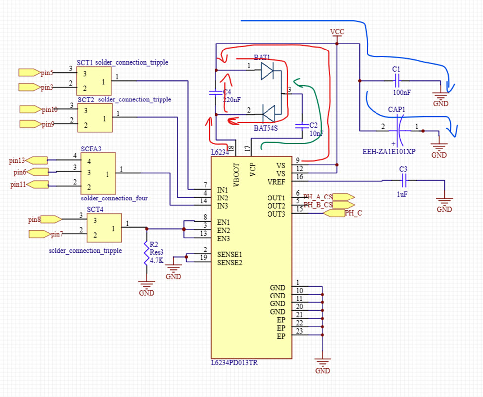
So I saw the schematic of the SimpleFOC shield 2.0.4, and the connection of the bootstrap capacitor is:
The C4 bootstrap capacitor is between the diodes, conecting in VBOOT and VCC.
In the first image (datasheet) the bootstrap capacitor is connected between the diodes VBOOT and then to GND.
I try to connect the capacitor like the SimpleFOC Shield and my motor spins well.