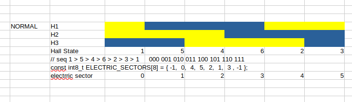
The important thing is the ELECTRIC_SECTOR which provides a mapping between the hall state and the electric sector. In the normal code a hall state of 0 and 7 are impossible and thus they are padded with -1. Given electric sector of [-1, 0, 4, 5, 2, 1, 3, -1] I can say that if the hall state is ‘3’ then by reading the electrict_sector[3] I can see that I’m in sector 5. similar a hall state of 4 is an an electric sector of 2.
Maybe there should be a separate hall sensors table for Gray coding, what OP is using? I think this is standard for reducing errors due to noise as only one bit changes per transition so it’s easier to reject “false” triggers.
Can’t one also do the Gray codes with more than 3 bits? Could this open the door to hall sensors with higher resolution? Sorry if its a stupid question…
Certainly not stupid But after a bit of playing with the idea, it looks like the number of steps per electrical revolution is always twice the number of sensors. Probably not enough improvement to bother with.
that worked great. Just added the new array into library.
Have two other issues:
Our hall sensors are not perfectly symmetrical so the is a difference for CW and CCW rotation. 4.19 and 5.24 looks to be the difference. Is it possible in simplefoc to have different offset values for CW and CCW commutation?
Sounds normal that the offset corresponds to 120 degrees as the hall sensors are not placed perfectly between motor coils. They are offset to one side so the other side should be offset the same amount just the other way?
Changing works, but at higher speed the offset should be changed.
Starting at 4.19 works fine to a target voltage of 10 but above that the current rises.
Changing offset to 3.9 allows driving it to target voltage of 20 with same current as target voltage at 10.
Is there a function in simplefoc to create an adaptive zero offset table or should we do something completely different?
 sensor.init();
  sensor.enableInterrupts(doA, doB, doC);
  // link the motor to the sensor
  motor.linkSensor(&sensor);

// link current sense and driver
current_sense.linkDriver(&driver);


  // driver config
  // power supply voltage [V]
  driver.voltage_power_supply = 48;
  driver.init();
  // link driver
  motor.linkDriver(&driver);

  // aligning voltage
  motor.voltage_sensor_align = 1;

  // set motion control loop to be used
  motor.torque_controller = TorqueControlType::voltage;
  motor.controller = MotionControlType::torque;

  // add current limit
  // motor.phase_resistance = 3.52 // [Ohm]
  // motor.current_limit = 2;   // [Amps] - if phase resistance defined
motor.voltage_limit = 25;
  // use monitoring with serial
  Serial1.begin(115200);
  // comment out if not needed
  motor.useMonitoring(Serial1);

  // initialize motor
  motor.init();


  // align sensor and start FOC
  motor.initFOC(4.19,CCW);

  // set the initial motor target
  // motor.target = 0.2; // Amps - if phase resistance defined
  motor.target = 2; // Volts
Is the underlying problem about bad hall placement?
It would be good to see some photos of your halls and the calculations you used to decide how far to space them. i.e. the motor has 6PP and thus each PP covers 60deg. We place halls at 0deg, 20 deg, and 40deg. I think some people put it across 3 poles e.g. at 0, 4/3, 8/3 (i.e. 0 deg, 80 deg and 160deg)