Hi guys, i have tried to read current signal through IOUTB & IOUTC pin of DRV8302 using Arduino UNO.
i’m using AnalogRead function to read those pins, and here’s the data that i got.
I get current data on phase B in the range of 390 while the current on phase C is in the range of 330.
i’m using 9V supply to DRV8302. i still confused about, what units are read from the pin? is it amperes or milliamps?
The return of analogRead() is an integer, on the UNO it is 10 bit resolution. The meaning of the value depends on how you have configured the hardware.
Without knowing more about your hardware configuration we can’t really say what’s going on. The meaning of the value will differ depending on the configuration (inline, low-side), the value of the shunt resistor and other components used in the analog section of the hardware, and the gain value configured on the DRV8302…
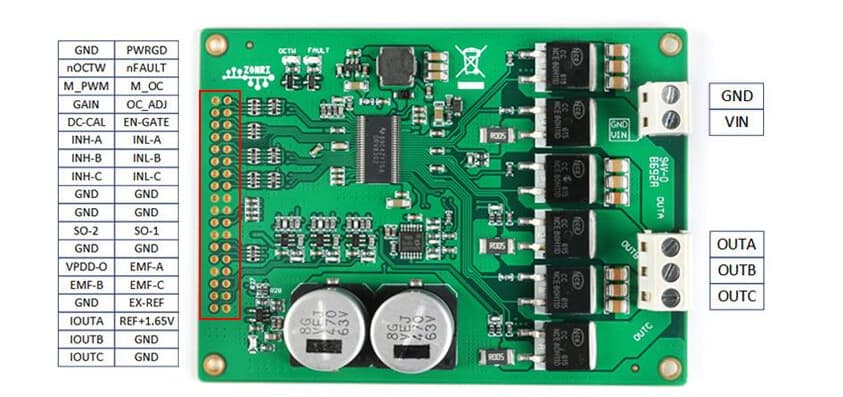
Hi @runger thanks for answering my question. based on the documents of the drv8302 module that i bought, i think it is inline configuration. here i attach the picture of it
Hi @runger from the documents i know that the gain is 12.2 but i’m not sure yet for the value of r shunt yet.
here i attach the schematics that i got from the documents. i think its related to current sensing pins.
The shunt resistor is not part of the picture you provided, therefore, no.
Is your question asking us to calculate it for you? At 12V/V (which is really low btw) for example to measure inline 10A bidirectional with 3.3V sensing logic you need about 10mO current sense resistor.
If I understood correctly, you have existing hardware, right?
The circuit you sent doesn’t include the shunt, as @Valentine already mentioned. The shunts (looks like there will be three of them) will be in another part of the circuit, between the SNx and SPx labels.
The part of circuit you’ve shown is the amplification for the current sensing signal, in this case using a op-amp rather than a dedicated current sense amp.
It looks relatively straightforward, with negative feedback and balanced resistor values, and a 1.65V reference to “centre” the output and allow bi-directional measurement. You can understand the circuit, and using the resistor values shown, the shunt resistor values (assuming you can find them in another part of the circuit diagram), and the op-amp datasheet you can figure out the gain.
Or you can test it empirically - assuming you have a power supply that shows the current drawn and some power resistors to help limit the current, you could pass some known current of, for example, 0.5A, 1A and 2A through the circuit, and check the voltage levels at the points labelled CSH-x to calculate the amps to volts conversion from the measurements.
Or you can ask the supplier for the gain value if they know it.
Or, if you have a firmware code for the board in question, you can extract the gain value from that code.
No, looking at that picture, this is a low-side configuration for the current sensing. The inline portion is labelled “BEMF Buffer”, so this is for voltage sensing. Its not needed for SimpleFOC.
The current sensing portion is connected between the FETs and GND, so low-side. And it isn’t using the DRV8302’s built in current sense amps, by the look of things in the block diagram and the part of the circuit you sent, they implemented their own amplification using op-amps.
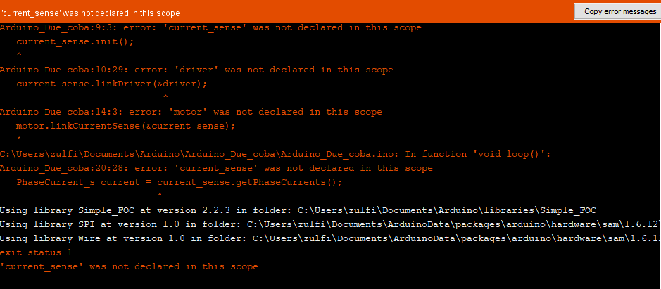
using this code, should i be able to get the current value in each phase?
i haven’t tried it yet, i was planning to try it on arduino due, but it says it doesn’t work on arduino due.
is there any code example that i can try? i’m using DRV8302 module from zonri tech with 12.2f gain, 0.005f (5milliOhm) shunt, with lowside configuration and BLDC motors. i need to get the current of each phase.
I’ve been able to use that exact board with a Nucleo F401 board. The ST processors are well supported by SimpleFOC code, and current sensing works well. I can read the per phase currents from the discrete current shunts on the Zonri board. I highly suggest you try an ST micro, or at least an ESP.
Yeah, unfortunately we don’t support low side sensing on the Arduino Due… why not? Not sure, I don’t have a Due myself.
Low-side sensing is a very complex thing, where the ADC readings have to be timed exactly to match the PWM so that the values are read when the low side FETs are conducting. Not all MCUs support it on the one hard, and on the other hand we have not implemented it yet on all MCU types we support for PWM drivers.
Not sure which is the case for Due.
As you can see from the compatibility table, you have to use a STM32 or ESP32 at the moment for low side sensing.
On these MCU types, the code should compile as expected…
Hi @wrcman555 thanks for your answer, do i need a logic level converter if i use this board with stm32/esp32? or do I just need to connect the pin like on Arduino UNO? because the voltage level of stm32/esp32 are different with Arduino UNO. i have make code that works well on arduino uno, but it doesn’t work on Arduino DUE
TBH we don’t know from these pictures… do you maybe have a link to the product page for it?
The fact that it uses a 1.65V reference suggests to me that it is using 3.3V logic. You could check with a multimeter. The output of the PWRGD, nFAULT and nOCTW pins should all be “logic high” if there are no errors. So with a multi-meter in DC voltage mode you could measure the voltage at these pins to know the logic levels.
The board also seems to have lots of little ICs near the IO pins which the IO lines seem to be passing through - so maybe it already has level shifters integrated and doesn’t care which logic level you use?
We recommend you start easy and get more complicated progressively. So the order of things to check is:
check motor resistance and set voltage limits, PSU voltage and max current (if you can) to a level where you don’t damage anything
try open loop velocity mode
try standalone sensor test code
try standalone current sensing test code
try closed-loop torque voltage mode
try closed-loop velocity mode, tune the PIDs
try closed-loop position mode
try closed-loop torque-current mode
We have sample code for all these things, but you may need to adapt it to your MCU/Sensor/Driver and set the correct pins, limits, etc… in each case.
@zulfiar-am With the Nucleo F401 board, it just works, no level shifting needed. I haven’t probed the current sense raw outputs to see the voltage range, but the Arduino compatible analog inputs on the Nucleo are 5V tolerant. Below is a picture of my “motor controller” - you can see the green current sense output wires going to A0/A1/A2 inputs on the Nucleo Arudino pins. Glad to share my code with you. Also note that I’m using it drive a large industrial AC servo motor, and use a AS5048A angle sensor (thanks @runger)!
Hi @wrcman555, do i need to connect the “Ref+1.65V” pin of the DRV8302 module if i want to interface it using 32bit microcontrollers that have 3.3v voltage level?
if i want to interface it using 3.3v voltage level microcontrollers, do i need to connect the REF 1.65 pin? if yes how can i generate 1.65 voltage to connect to reference pin?
I guess so, but I cannot say without seeing more documentation or the whole schematics.
I think the 1.65V is intended as an input, but it could be an output for an on-board reference voltage. One way to check it is to power up the board and see whether there is a voltage on this pin or not.
If you need to generate it, there are a few ways:
easiest is a voltage divider, divide your MCU voltage by 2 using two equal valued resistors like 10k/10k.
best quality is probably a chip voltage reference, there are many available and they produce a very stable, clean reference voltage. A chip like the MAX6018BEUR16.
or if your MCU has a DAC output, you could generate a 1.65 reference voltage through the DAC, and a simple R-C filter.
probably some other people here can think of a few more