Firstly, thank you for all the efforts everyone has put into this. This is a great community.
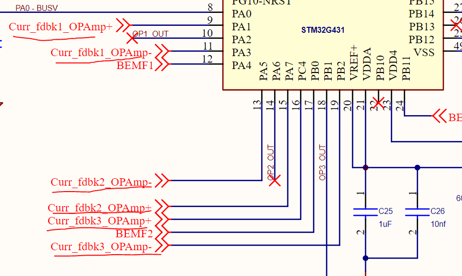
I’m trying to attempt a custom board based off of the B-G431B-ESC1, rated for 56V and 10A. The B-G341 is rated for 24V and 40A. I’m stuck on the current sense setup. The B-G431B-ESC1 uses internal OpAmps for current measurements as shown in their schematic below.
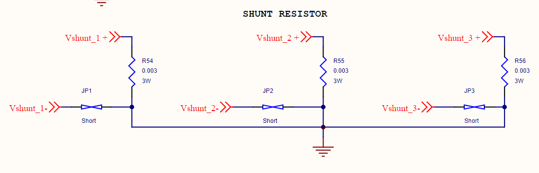
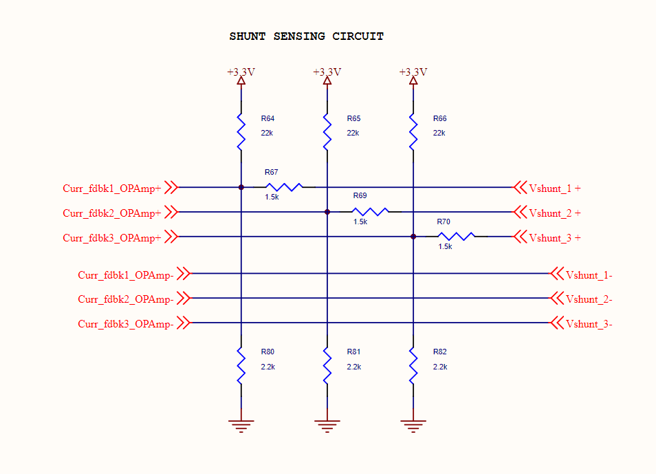
Firstly, I’m not sure if I need to make any changes to the sensing circuit (other than changing the shunt resistor to a higher wattage value) as my current capacity is not increasing.
I saw in this post how the max gain is 16 which brings the ADC value under 1.6V. But since my current rating is under 40A, I’m hoping my ADC will read under 1.65V (without burning the ST).
But the voltage is increasing from 24 to 48V, and I don’t know if that translates onto the current measurement (which is nothing but voltage drop across the shunt resistor).
This is another post where others have tried attempting a similar setup.
If anyone has an idea on how to go about setting up current sense with the internal opAmps. I’m trying my best to recreate the B-G431B-ESC1 setup as it worked great with simpleFOC (only limiting factor being the 24V rating).