B-G431B-ESC1 Current Control

Hi All,

I’ve got a basic level of current control working for the B-G431B-ESC1 devkit. The branch is here.
I was wondering if anybody else (@Owen_Williams ?) was looking into this and if I might be able to help out?
It’s a bit of a mess as it’s very hardware specific and I’ve made heavy use of the STM32CUBE IDE HAL.
It also doesn’t run smooth and I’m not entirely sure why.
But the ADC DMA and OPAMP are working and I get reasonable measurements.
image
I intend to implement more functions from the MIT mini cheetah to hopefully one day get full torque control.
I’ll be working to make it more acceptable but it will be a while before it’s up-to the simple FOC standards.

Thanks for making this awesome project. I’ve been trying to build a BLDC controller for a while but hadn’t made much progress until now,
Scouttman

4 Likes

Hey @scouttman!

Wow great work, we’ve been doing almost the same thing :smiley:
I’ve implemented the interface for the true torque control (for now just the inline sensing) in the dev branch!
:smiley:
Your code is great and I’ll refactor it easily to fit into the new simplefoc api.

The difference in between new simplefoc code and yours is that I intended to provide 3 types of torque control:

  • voltage based
  • current baser (but just one current more suitable for mcus like arduino uno and such)
  • full foc control (dq current)

And then I intended to use the ControlType as a motion control selector where you can decide to do:
torque, velocity and position control. And each of these motion control startegies will use the torque controller you selected.

So the code would be something like this:

motor.torque_controller = TorqueControlType:foc_current;
motor.controller = MotionControlType::velocity;
1 Like

Welcome @scouttman,
That is great! I spent a few hours a few months back trying to get the inbuilt OPAMP and ADC of the stm32g431 configured properly but didn’t get very far. I’m not experienced enough to navigate the stm documentation and HAL layers!

From the graph it looks like you’ve cracked the hardware specific part. It would be great to see this integrated! :clap:

1 Like

Awesome @Antun_Skuric,

That sounds great. Seems like a very clean and comprehensive approach to the problem.
Cant wait for full FOC control.
I’ll have to checkout the dev branch and have a poke around and see what I can get going.
@Owen_Williams it was mostly just blind stumbling around the the CubeIDE GUI randomly changing things until they started working :stuck_out_tongue:.

1 Like

Good work guys. In the source i see that using min 2 phase at current sensing. I had combined 3 current sensors on my v1 board and also v2 schematic. Do you think I should separate them? At least 2 of them?
schematic:

I’m a bit out of my depth here but firstly have you put r13 in the wrong place? I can see two 10k resistors on datasheet but not near current measuring.

You are putting all the output currents through the same Ris.
So your main question is, is this ok? What am i losing?

You won’t be able to do sensorless FOC. You will be able to do current limits. I’m not sure if the algorithms being implemented by Antun need to see current in at least two phases. My guess is that @Antun_Skuric will be using/assuming 3 phase current measurement so it might be easier to tweak your design to read 3x currents.

Are you confident that the 3x btns can have their current combined in this way?

@Owen_Williams In the application note, if IN1 is high IS pin voltage output, if IN1 is low IS will 0. So there is a pwm signal on the Is pin.
R13 and C7 are used for lowpass filtering to linear voltage output.
(Blue line is Vis in my schematic.)

According to this, if only one btn is active each time in the BLDC driving, then each IS outputs one by one. So I can combine all ISs, right?.

Hey @alp,

If you want to do the FOC control you do not really need the third current sense. You can have it for back emf and similar applications where the current does not pass through all the phases at the same time.

For sinusoidal currents you can always find the third current by calculating:
ic = 0 -ia -ib

We will be supporting both two and three current so you can choose which one suites you more.
Three currents is more robust because you have more measurements and on average less error.

Regarding the 3btns on one pin. Honestly this is all an ok option but I am not 100% sure that simplefoc will support this natively. We will try to support low-side (3x or 2x), inline and high side.
But low side with one shunt requires a very high degree of synchronisation and it is not at all inpossible but makes things even more hardware specific than just low-side sensing. So i would suggest you to separate these pins so that you can read them at the same time.

Btw, when you put as requirement that the btns should not be on at the same time, for the center aligned pwm modulation this will almost never be the case. But this is not really a requirement, more of them can be open at the same time, but not all low or high side ones.

There is a nice thread where @robin2906 well explained the problems of this approach:
https://community.simplefoc.com/t/advice-on-current-sensing-for-new-board-design/206/40?u=antun_skuric

I hope I didn’t confuse you with my post. :smiley:

No, thanks your comment. I’m new to FOC and BLDC driving, sometimes i need help about this and i learn new things here everyday.
Ok, i will separate all sense pin. So it will have 3x and highside(btns has).

Hey @alp,

I have the same question, will we be able to measure phase currents by using multiple high-side amps.
Honestly I do not know.

I have spent few hours in research and it seems to be very very unusual approach, maybe even too unusual. I was not really able to find anything about it. Here are some very nice pdf’s explaining different approaches:

https://www.st.com/resource/en/application_note/dm00666970-current-sensing-in-bldc-motor-application-stmicroelectronics.pdf

This article is also nice:

The guys says:

High-side dc-link sensing is typically used only for fault detection. It has the advantage of having a stable common-mode voltage and enables motor fault detection. However, depending on the motor, the common-mode voltage could be very high, limiting the choice of devices able to be used in this implementation. In addition, the driver current, which is actually what’s being measured, doesn’t necessarily equal motor phase current.

I suppose for DC motor it really does not matter which one of the current sense techniques you use because there is always only one current. And high-side is nice because you can sense the short-circuits. But for BLDC’s it seems to be very uncommon technique. You can see that in all of those links above you will not find multiple high-side current sense amps.

But in regards to your question, I would still suggest you to separate them. And then, if that is the only way, you can sum the adc readings in the code.

I have made a board that uses the btn8982 as well, and it will come I hope tomorrow so I’ll look into it a bit more in depth. It would be awesome if we could do current control using these drivers, it would make these drivers absolute winners!
If not, that would mean that we need to add additional current sense resistors and amps to the board, and that all becomes complicated.

Sometimes just have to try and see :grinning:. Actually, SimpleFoc has no goal of making industrial drives, right? It already works pretty well. If we can measure current and use it, it will be a big improvement for the hobby, even if it has some disadvantages.
My goal is to make BLDC Servo that is cheap like RC SERVO but can be used in my robots. Yes BTNs are really good, mosfet + mosfet driver + current sensor + high power and less component.
All of my parts are freezing on the way. I think it’s because of the Chinese holiday. So i look forward to your work with your new Btn8982 board. I hope everything will be fine.
Finally separated sense pins and added some caps for emi. 42x42mm pcb:


2 Likes

Hello @alp, @Antun_Skuric,
Do you think it would be possible to put 2 BTN or IXF in parallel by branch to increase the current again ?

Hi @Marc_O
This is possible but should not be preferred. Btn8982 is the half bridge driver. They must be triggered at exactly the same time otherwise +Vdd and gnd will be short circuited.

Have you considered using higher voltages? There’s lots of drivers and mosfets in the higher voltage ranges, and your currents will be lower… would there be a disadvantage to that approach?

How about gears?

Otherwise I’ve found both IGBTs and GanFETs that can handle more current than MOSFETs - they have lower RDSon… Although I haven’t yet seen any designs based on those kinds of power switches it should be possible…

This article explain STM ESC and FOC in simple but detailed manner for anybody interested:

https://www.embedded.com/key-factors-in-designing-a-drones-electronic-speed-control/

Thanks.

1 Like

Hi @scouttman!

Thanks for your work! :slight_smile:. I am trying to implement bits of your code to also get FOC current mode working. Are you still working on it?

I was curious how the implementation is going for you? Does it run smooth already? :slight_smile:

Hi @ultra.robotics,
I’ve been a bit slack on this. I pulled in and old develop and got it working with Antun’s current control.
The branch is B-G431-ESC1_current_measurment_test.
It seemed to worked out of the box and seemed fairly stable although I haven’t really tested. I have it connected to a linear actuator and with a simple controller it seems to act like a spring.
The messy part is the HAL layers. I followed Antun’s new structure and it’s neater now but it’s very hardware specific and I lost interest when I wasn’t easily able to come up with a solution. Also I previously forgot to mention it requires some new call backs in the Arduino functions and also for some default libraries to be disabled. I just pushed some example code.
I’ll also try to pull in the latest develop and see if it still works.
I’ll try to move the callbacks into the simpleFOC code.
Very excited to keep working on this, let me know if you have any question or suggestions on how to fix things.

2 Likes

I can’t get your code to work. With these build flags:

#define HAL_OPAMP_MODULE_ENABLED
#define HAL_ADC_MODULE_ONLY

There is a failure in:
_configureADC()MX_ADC1_Init()HAL_ADC_Init()
around line 495 of framework-arduinoststm32\system\Drivers\STM32G4xx_HAL_Driver\Src\stm32g4xx_hal_adc.c it attempts to enable the internal voltage regulator with LL_ADC_EnableInternalRegulator(), but this fails as LL_ADC_IsInternalRegulatorEnabled() returns negative just a few lines later.

With these modified build flags:

#define HAL_OPAMP_MODULE_ENABLED
#define HAL_ADC_MODULE_ENABLED

Enabling the ADC regulator succeeds. But the code fails later:
HAL_ADC_Start_DMA()HAL_ADC_Start_DMA()ADC_Enable()
Around line 3450, the ADC is enabled with LL_ADC_Enable(), a few lines later readyness is verified with while (__HAL_ADC_GET_FLAG(hadc, ADC_FLAG_RDY) == 0UL) { .... }, but this fails.

Any pointers?

Edit: I was able to fix the first issue by calling __HAL_RCC_ADC12_CLK_ENABLE(), this allows me to get past LL_ADC_IsInternalRegulatorEnabled(). However, I’m still not able to get past the ADC readiness checks.

Ahh yes sorry about that.
If my memory serves me correctly I needed to disable the stmduino ADC initialisation so that the modified MX_ADC1_Init is called so we can get DMA.
I faced the same ADC issue caused by __HAL_RCC_ADC12_CLK_ENABLE() and found the solution here. Apologise for not including it.
When I have some more time I’ll try to see what else could cause that error.
Good luck thanks for having a look at it.

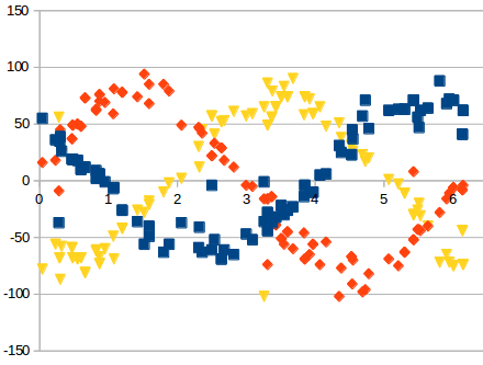
I’m able to get some current readings.

This code was needed to enable the ADC clock as mentioned earlier.

  __HAL_RCC_ADC12_CLK_ENABLE();

The following code enables the ADC for usage with an asynchronous clock.

// RCC_ADCCLKSOURCE_PLL enable:                       (optional: if asynchronous clock selected)
RCC_PeriphCLKInitTypeDef PeriphClkInit;
PeriphClkInit.PeriphClockSelection   = RCC_PERIPHCLK_ADC12;
PeriphClkInit.Adc12ClockSelection    = RCC_ADC12CLKSOURCE_PLL;
HAL_RCCEx_PeriphCLKConfig(&PeriphClkInit);

The following piece of DMA initialization code was missing (similarly for DMA1_Channel1)

  static DMA_HandleTypeDef hdma_adc2;

  /* Config DMA *****************************************************************/
  hdma_adc2.Instance = DMA1_Channel2;
  hdma_adc2.Init.Request = DMA_REQUEST_ADC2;
  hdma_adc2.Init.Direction = DMA_PERIPH_TO_MEMORY;
  hdma_adc2.Init.PeriphInc = DMA_PINC_DISABLE;
  hdma_adc2.Init.MemInc = DMA_MINC_ENABLE;
  hdma_adc2.Init.PeriphDataAlignment = DMA_PDATAALIGN_HALFWORD;
  hdma_adc2.Init.MemDataAlignment = DMA_MDATAALIGN_HALFWORD;
  hdma_adc2.Init.Mode = DMA_CIRCULAR;
  hdma_adc2.Init.Priority = DMA_PRIORITY_LOW;
  HAL_DMA_DeInit(&hdma_adc2);
  HAL_DMA_Init(&hdma_adc2);

  __HAL_LINKDMA(&hadc2, DMA_Handle, hdma_adc2);

The DMA interrupt handler needs to be defined within extern “C” blocks. (similarly for DMA1_Channel1)

extern "C" {
void DMA1_Channel2_IRQHandler(void) {
   HAL_DMA_IRQHandler(&hdma_adc2);
}
}

Only the following define is needed for compilation

#define HAL_OPAMP_MODULE_ENABLED

With these adjustments and the code from:
src/current_sense/hardware_specific/stm32g4_hal.h
src/current_sense/hardware_specific/stm32g4_hal.cpp
src/current_sense/hardware_specific/stm32g4_mcu.cpp
src/drivers/hardware_specific/stm32_mcu.cpp

The readings themselves appear to be wrong, but that’s something for future work. At least I get some readings that are correlated to the motor voltage.

Where did you get the value of 64/7 located in examples/hardware_specific_examples/B-G431B-ESC1/B-G431B-ESC1_current_control/B-G431B-ESC1_current_control.ino? Using this scaling seems to result in the correct current readings, but I’m unable to find any documentation referring to this value.