Beginner help with Hobbysky BLDC 6374 With Hall Sensor

Hello everyone,

I am completely new to Arduino and even more so to motors. I have a few questions and hopefully this is the appropriate venue.

This is a list of the hardware that I am working with:

Arduino:
ELEGOO MEGA R3 Board ATmega 2560

SimpleFOC Board:
Makerbase SimpleFOC Shield V2.0.4 FOC BLDC Motor Controller Board Arduino Servo
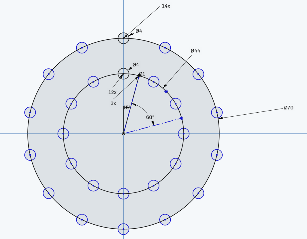
Motor:
https://www.amazon.com/dp/B07PNMYHFT?ref=ppx_yo2ov_dt_b_product_details&th=1

I purchased the above shield and it appears to me that you can just squish it onto the mega which leads to the first question. Is this connection method appropriate? My intuition goes like this: the labels on the silkscreens of both boards line up and seems like it would be fine. Is this the case?

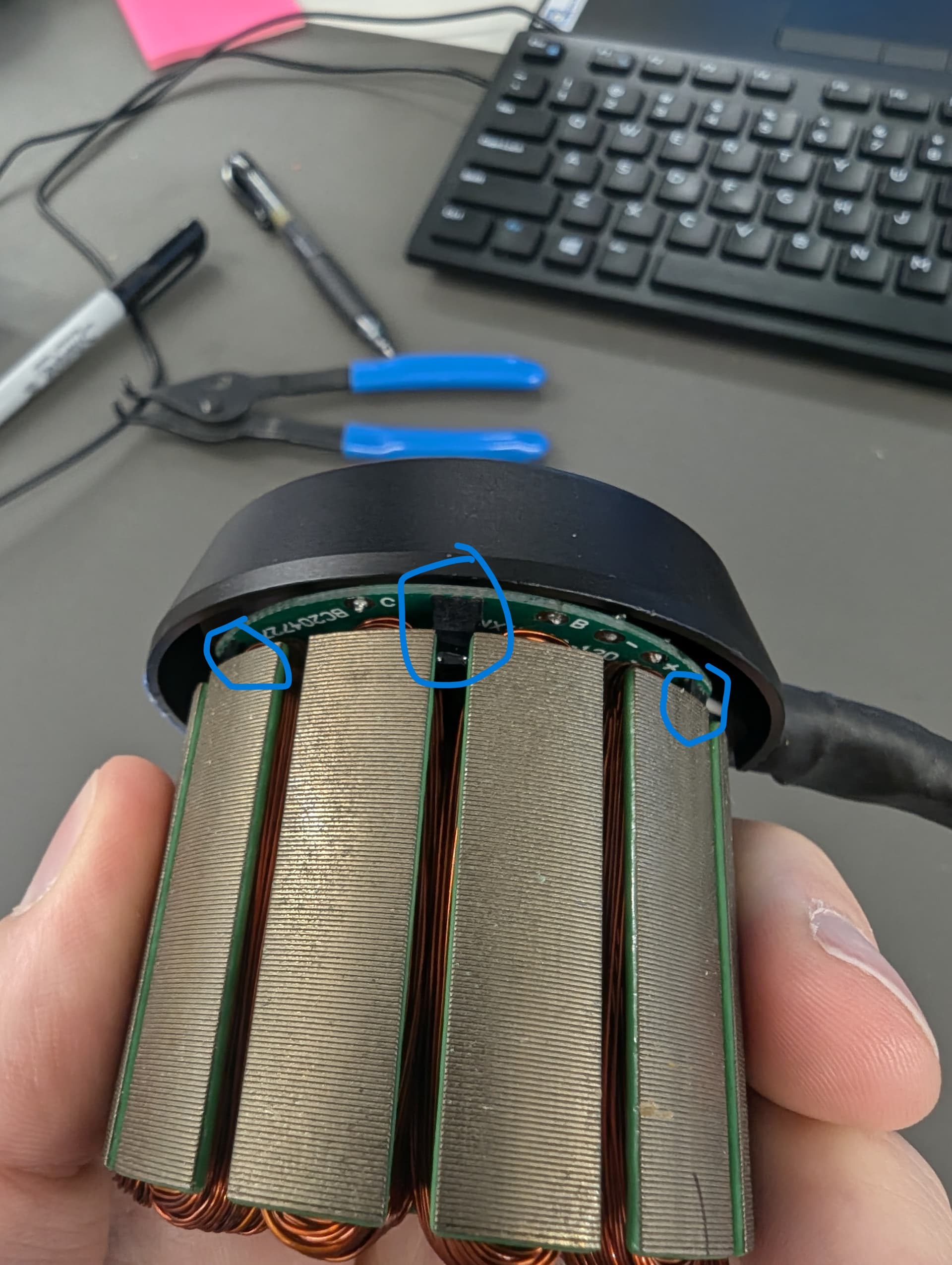
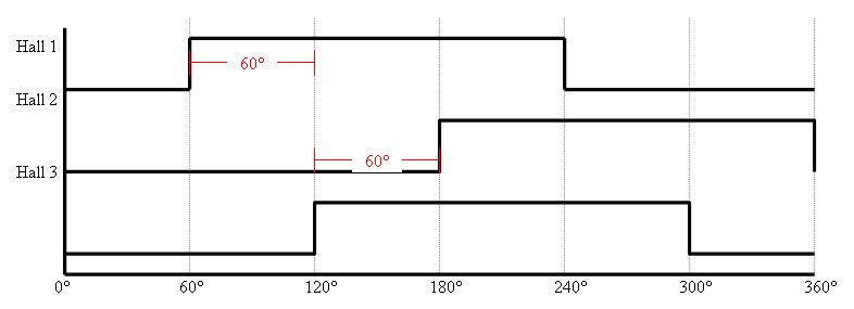
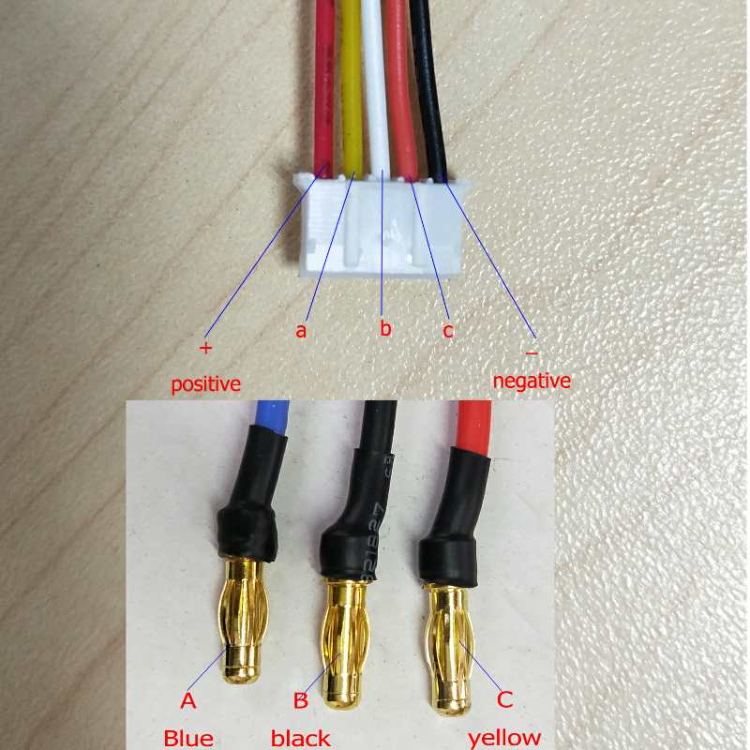
The next question(s) is about where to connect the sensors to the shield. I did some looking around and came to realize that there are many types of hall sensors and they can be analog or digital. I did watch this video: https://www.youtube.com/watch?v=q4BkhwoGzbM and if I understood it correctly I can apply 5v and connect ground to check if the sensor resistance is in a center region around 2.5v which would likely mean it is an analog sensor and it would be connected to a different region on the mega/shield. If it is around 0v or 5v it would indicate it is digital and would need to be connected to a different area on the shield. Is this a good way to see if this motor uses digital or analog sensors?

I think that is it for now. I hope that this is clear and if not I will try to clarify.
Thank you to anyone who helps

Welcome!

That’s a pretty big motor, so be careful with the voltage limit until you get it running well. Phase resistance will probably be around 0.1 Ohm, and that board says 5A peak, so to be safe try 0.1V to start and if nothing gets hot try 0.2V. Assume the transistors will explode until proven otherwise :slight_smile: Safety glasses are good insurance.

Question 1: Yes, that is how shields are intended to be connected.

Question 2: The sensors will almost certainly be the digital/latching type. Power with 5V and connect to Uno pins 2, 3, 4 as in the hall sensor examples.

Thank you for the prompt response and the heads up. I am building a record cutting lathe and I need the motor to sling around a big plate but not very fast. I figured I should go overkill on the motor so it wouldn’t stall.

Hi,

Thank you for sharing this information.

Hello again,

I started to connect things and using sensor_test. I have my 5v and GND connected on the “power” side of the arduino. For the hall sensors I have them connected per this image https://p.globalsources.com/IMAGES/PDT/B5957549339/Agv-Motor.png which was emailed to me when I asked for a diagram from the amazon seller. I have connected A to pin 2, B to pin 3 and C to pin 4.

When running sensor_test and turning the motor I do not get a value of 6.28rad. The serial monitor reads -0.07 rad when started. Then when I rotate the motor one revolution I get a number of different values (when closing and reopening the monitor and rotating the motor) 0.37, 0.82, -0.07. Turning the motor back does not return the value to the starting one.

I tried changing the internal pullup setting and the behavior is the same with differing values.

Does this mean that the sensors are connected in the incorrect order?

They will work in any order. It just changes the direction and zero angle found by the calibration procedure.

Check that you have the pole count right. The hall sensor example uses 11, but your motor is 7. So the hall sensor constructor should look like HallSensor sensor = HallSensor(2, 3, 4, 7);

And do set sensor.pullup = Pullup::USE_INTERN; before calling sensor.init(). It shouldn’t hurt anything even if your driver does have pullup resistors.

Try printing out some stuff a couple times per second to see what it’s doing.

void loop() {
  sensor.update();

  static uint32_t lastPrintTime = millis();
  uint32_t time = millis();
  if (time > lastPrintTime + 500) {
    lastPrintTime = time;
    Serial.print("Angle "); Serial.print(sensor.getAngle());
    Serial.print(", state "); Serial.print(sensor.hall_state);
    Serial.print(", sector "); Serial.print(sensor.electric_sector);
    Serial.print(", rotations "); Serial.print(sensor.electric_rotations);
    Serial.print(", interrupts "); Serial.println(sensor.total_interrupts);
  }
}

Okay so after changing those values the senor reads 0.15 when starting the serial monitor. Rotating the motor once gives 2.84, 1.94, 1.65. Sometimes when starting the monitor the value is -0.15 and rotating the motor once gives a value of 0.15. I am not sure why this is as I just close and reopen the monitor without changing anything physically.

Uploading the code you posted gives a starting result of:
Angle 0.15, state 5, sector 1, rotations 0, interrupts 1

Rotating the motor once gives
Angle -0.15, state 7, sector -1, rotations 0, interrupts 42
Here is some of the serial monitor output:
17:12:57.267 → Angle -0.15, stat, sector -1, rotations 0, interrupts 43
17:12:58.153 → Sensor ready
17:12:59.670 → Angle -0.15, state 7, sector -1, rotations 0, interrupts 1
17:13:00.176 → Angle -0.15, state 7, sector -1, rotations 0, interrupts 1
17:13:00.663 → Angle -0.15, state 7, sector -1, rotations 0, interrupts 1
17:13:01.152 → Angle -0.15, state 7, sector -1, rotations 0, interrupts 1
17:13:01.672 → Angle -0.15, state 7, sector -1, rotations 0, interrupts 1
17:13:02.163 → Angle -0.15, state 3, sector 5, rotations -1, interrupts 18
17:13:02.665 → Angle 0.30, state 4, sector 2, rotations 0, interrupts 33
17:13:03.170 → Angle -0.30, state 2, sector 4, rotations -1, interrupts 41
17:13:03.661 → Angle -0.15, state 7, sector -1, rotations 0, interrupts 43
17:13:04.150 → Angle -0.15, state 7, sector -1, rotations 0, interrupts 43
17:13:04.635 → Angle -0.15, state 7, sector -1, rotations 0, interrupts 43
Another rotation
17:13:35.211 → Angle -0.15, state 7, sector -1, rotations 0, interrupts 43
17:13:35.713 → Angle 0.30, state 4, sector 2, rotations 0, interrupts 45
17:13:36.176 → Angle 0.15, state 5, sector 1, rotations 0, interrupts 62
17:13:36.680 → Angle -0.30, state 2, sector 4, rotations -1, interrupts 77
17:13:37.209 → Angle -0.15, state 3, sector 5, rotations -1, interrupts 84
17:13:37.683 → Angle 0.15, state 5, sector 1, rotations 0, interrupts 86

What is being measured by the state and sector values?

State is the raw hall sensor values and should cycle through values 1,3,2,6,4,5 forward or backward (binary 001,011,010,110,100,101) as the sensors switch on and off when you turn the motor. Sector is like an index into that sequence, so it counts 0,1,2,3,4,5. States 0 and 7 (all sensors off or all on) should never happen. Sector is set to -1 when the state is invalid. So something’s not right, and the angle/rotations are meaningless.

The relatively large numbers of interrupts may mean the internal pullups aren’t strong enough and the sensor output is fluctuating randomly. If you have a breadboard and jumper wires, try connecting some resistors and see if that makes any difference. Around 1k-4.7k should do it.

You could also try the version of HallSensor from the dev branch. @Candas1 recently modified it so it can work without interrupts, which works better with jittery sensors. If you remove the call to enableInterrupts, it will read the hall state each time sensor.update() is called, which is normally often enough that you don’t lose position. The velocity reading is a little less accurate, but the lowpass filtering smooths it out for the most part.

Actually it was already released in v2.3.4, I would be curious to know if it helps in this situation.

Okay so I don’t really understand why but, I was able get a correct value of 6.28. The changes that were made were switching to the hall_sensor_software_interrupts_example sketch, with the specific wiring B, C, A, and with no additional resistors. This is the serial data for this (one rotation):

19:01:05.842 → Sensor ready
19:01:07.370 → Angle 0.00, state 1, sector 0, rotations 0, interrupts 1
19:01:07.872 → Angle 0.00, state 1, sector 0, rotations 0, interrupts 1
19:01:08.361 → Angle 1.65, state 3, sector 5, rotations 1, interrupts 12
19:01:08.864 → Angle 3.44, state 7, sector -1, rotations 4, interrupts 23
19:01:09.328 → Angle 4.94, state 6, sector 3, rotations 5, interrupts 34
19:01:09.872 → Angle 5.39, state 1, sector 0, rotations 6, interrupts 37
19:01:10.332 → Angle 5.83, state 6, sector 3, rotations 6, interrupts 40
19:01:10.864 → Angle 6.28, state 1, sector 0, rotations 7, interrupts 43

This is the output of A,B,C:
19:03:40.908 → Sensor ready
19:03:42.408 → Angle 0.30, state 4, sector 2, rotations 0, interrupts 1
19:03:42.911 → Angle 0.30, state 4, sector 2, rotations 0, interrupts 1
19:03:43.425 → Angle 0.30, state 4, sector 2, rotations 0, interrupts 1
19:03:43.913 → Angle 0.30, state 4, sector 2, rotations 0, interrupts 1
19:03:44.384 → Angle 0.30, state 4, sector 2, rotations 0, interrupts 1
19:03:44.905 → Angle 0.30, state 4, sector 2, rotations 0, interrupts 1
19:03:45.410 → Angle 0.30, state 4, sector 2, rotations 0, interrupts 1
19:03:45.887 → Angle 0.30, state 4, sector 2, rotations 0, interrupts 1
19:03:46.412 → Angle 0.30, state 4, sector 2, rotations 0, interrupts 1
19:03:46.929 → Angle -0.30, state 2, sector 4, rotations -1, interrupts 3
19:03:47.386 → Angle -0.15, state 7, sector -1, rotations 0, interrupts 17
19:03:47.913 → Angle 0.30, state 4, sector 2, rotations 0, interrupts 31
19:03:48.431 → Angle 0.30, state 4, sector 2, rotations 0, interrupts 37
19:03:48.934 → Angle -0.30, state 2, sector 4, rotations -1, interrupts 39
19:03:49.390 → Angle 0.30, state 4, sector 2, rotations 0, interrupts 43

I wont do the other positions but yeah, I don’t understand.

Adding 4.7k resistors does not change the output (B,C,A one revolution):
19:13:23.824 → Angle 0.00, state 1, sector 0, rotations 0, interrupts 1
19:13:24.326 → Angle 0.75, state 3, sector 5, rotations 0, interrupts 6
19:13:24.813 → Angle 2.69, state 1, sector 0, rotations 3, interrupts 19
19:13:25.324 → Angle 4.04, state 6, sector 3, rotations 4, interrupts 28
19:13:25.798 → Angle 4.79, state 4, sector 2, rotations 5, interrupts 33
19:13:26.314 → Angle 5.24, state 0, sector -1, rotations 6, interrupts 38
19:13:26.818 → Angle 6.28, state 1, sector 0, rotations 7, interrupts 43

I did try adding 2.7K and 4.7k resistors with the original sketch and the output was similar to the behavior outlined in my earlier post.

Just a quick note to add in here, just because a motor contains its own hall sensors doesn’t mean you can’t add other angular measurement systems of your own. I’m not sure to what extent a “record cutting” lathe should have precise position control vs having simply speed control, but if the internal hall sensors only get you 6 discrete locations per electrical revolution of the motor, you could always add a diametrically polarised magnet on the backshaft and put as AS5600 behind it, or 3d print a disc to attach to the motor with a bunch of tiny magnets embedded into it, and have these external tiny ones sweep past analogue, rather than latching, hall sensors.

1 Like

State 7 / sector -1(all hall high) and State 0 / sector -1(all hall low) shouldn’t happen with 120 degree hall placement.

I think you have 60 degree hall placement. You might have to invert the digital state of one hall.
For example inverting here:
B_active = ! digitalRead(pinB);

(Sorry I edited the message several times)

Or is it noise ? :thinking:

You are correct about the sensors being placed at 60 degrees. I opened up the motor and took a peek at it. There is a pcb in there that has the hall sensors attached. I then drew a little mock up of the motor just to check.

So I guess my question(s) now is, why does inverting the output of one of the sensors correct the issue? Could you do any of them? Additionally uh…where do I edit that file at? :sweat_smile:

Sorry about the double post. Here is an image of the inside of the motor and pcb

Nice catch, @Candas1!

You have to invert the middle sensor. For most pole/slot combos, spacing the sensors equally around the motor (120 degrees) will get you a valid placement. This placement is equivalent to that except the middle sensor has been moved to the other side of the motor. Since the rotor magnets are always a multiple of 2, this puts it in the same relative position but opposite polarity.

Unfortunately the SimpleFOC HallSensor class doesn’t provide any way to do it. But it’s easy to add. All you have to do is add a new variable invert_hall_state, set it to 2, and modify one line in HallSensor::updateState()
int8_t new_electric_sector = ELECTRIC_SECTORS[hall_state^invert_hall_state];

1 Like

I actually never owned one of those, but people use to share this page that explains it nicely.
I could only find it in the webarchive now, so I will copy the content here just in case:

120deg Hall Effect Sensors
The following diagram shows 120-degree hall-effect sensors. Notice that there is electrically 120 degrees between hall transitions.

60deg Hall Effect Sensors
The following diagram shows 60-degree hall-effect sensors. Notice the Hall 3 signal is inverted (compared to 120-degree hall3) This changes the number of electrical degrees between the rising edge of the hall states.


All of the hall motors Compumotor uses are 120degrees. If we use an inverter on Hall 3 we can change a 60degrees hall state to 120degrees and vise versa.

Now that I see it again, the diagram with the inverted hall signal is correct, but the explanation about the electrical degrees between hall transitions seems weird lol

1 Like

Sounds like an option we should add to the HallSensor class?

Either a simple option to flip one of the halls.
Or building the ELECTRIC_SECTORS array during the sensor alignment, but then you have to set it manually in the code or save it to eeprom. That’s much more complicated.

Yes, I think it’s worth supporting. This sensor placement is useful because it puts them exactly half way between 3 consecutive pairs of stator teeth, which can be done precisely by hand for motors that don’t come with sensors. And has them all close together for cleaner wire routing than 120 degree placement.

Hello again. More questions

With regard to the code (which I don’t understand all that much and will demonstrate lol) stuff for @Candas1 solution do I invert the state at line 32, 106 and 165 or just on one line? For @dekutree64 solution do I declare the variable in the HallSensor::updateState function ie:

void HallSensor::updateState() {
  int8_t new_hall_state = C_active + (B_active << 1) + (A_active << 2);

  int8_t invert_hall_state = 2;

  // glitch avoidance #1 - sometimes we get an interrupt but pins haven't changed
  if (new_hall_state == hall_state) return;

  long new_pulse_timestamp = _micros();
  hall_state = new_hall_state;

  int8_t new_electric_sector = ELECTRIC_SECTORS[hall_state ^ invert_hall_state];
  int8_t electric_sector_dif = new_electric_sector - electric_sector;

Or do I put that variable somewhere else? Additionally does either solution change the math done in Hallsensor::getSensorAngle()?

There are a few more things I have questions about in Step 2. Testing the driver + motor combination

@dekutree64 you were correct about the phase resistance. I measured 0.2 ohm across all combinations of pins

driver.voltage_power_supply: I would assume that this value at a minimum would need to be 18v per the motor parameters on the amazon page. The max for the motor is 42v but I would assume that the actual cap on voltage is dictated by the driver board (35v). Should I go higher on this value, maybe the middle of the range?

driver.voltage_limit: In the example code this value is set to half that of driver.voltage_power_supply is this what it should be in all cases? With my motor should it be the case that i use a driver.voltage_power_supply of 35v and set the limit to half of that to get close to the minimum voltage of the motor?

motor.voltage_limit. I understand that it must be different from the driver.voltage_limit but not exactly how it differs from the driver.voltage_limit in practice. Reading the commented code and the getting started page says the same thing that @dekutree64 said and if I pop in my values of 0.2 ohm and the suggested 2*phase_resistance, that is 0.4. Intuitively it seems low and runs counter to the code comment “start very low for high resistance motors” since the mentioned 10 ohm resistance is much higher than 0.2

Finally, when do I need to consider the Kv of the motor. Should it be a part of the decision making process for the above variables?

It feels like I am missing some assumptions or something. I apologize if any of this is unclear or scattered.

Anywho, thanks for your help