Looks like I share this in the wrong thread lol
From the diagrams I shared, it looks like inverting the wrong hall would still give you 111 or 000 states.
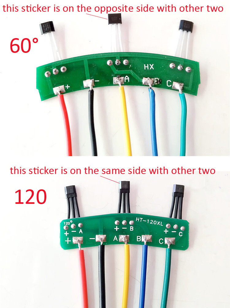
In the diagrams, hall 3 is inverted, but on the picture I shared, the middle one is inverted.
From your picture it’s unclear which one is inverted. I am not sure if they only solder the hall upside down, or if there are halls inverted internally.
if you are using enableinterrupts():
I would try to invert 26/31/37 one by one here until all the positions are valid.
if you are not using enableinterrupts():
I would invert 101/102/103 one by one here until all the positions are valid.
I think I would still check also if with the same wiring you get:
- 000 and 111 invalid states which would point to 60 degrees hall placement
- only 000 which could mean one hall is not wired well or defective (always OFF)
- only 111 which could mean one hall is shorted (always ON)
It will work if you declare invert_hall_state in updateState() like that, but for a proper implementation it should be a member variable so you can configure it from user code without modifying the library. Default 0, and set to 1, 2, or 4 (binary 001, 010, 100) to invert each of the sensors. You should never have to invert two sensors.
driver.voltage_power_supply must be set to the actual DC voltage you’re feeding it, nothing to do with motor ratings. The PWM duty values are calculated relative to this.
You generally don’t need to set driver.voltage_limit. It will automatically be set equal to voltage_power_supply.
motor.voltage_limit is what’s normally used to keep from drawing excessive current until you get it running well with the voltage-based current limiting. Then you can rely on motor.current_limit and increase voltage_limit so you can reach higher speeds.
motor.voltage_limit should usually be at most half of voltage_power_supply, because motor voltage gets multiplied by sine/cosine which range -1 to +1, so the actual voltage difference between motor wires can be twice the limit. It’s confusing.
That code comment “start very low for high resistance motors” in the getting started page is wrong. It should be “start very low for low resistance motors”.
1 Like
I did another test where I pulled rotor(? The part with the magnets and not the coils) and then did the sensor test and got this:
Sensor ready
Angle -0.15, state 7, sector -1, rotations 0, interrupts 1
I can latch the individual sensors with a magnet. Does this mean that all/none of them are inverted?
Further when I use notepad to change this line in HallSensor.cpp and then verify and upload the hall_sensor_software_interrupts_example
void HallSensor::handleA() {
  A_active = digitalRead(pinA);
  updateState();
}
to
void HallSensor::handleA() {
  A_active = !digitalRead(pinA);
  updateState();
}
I would expect a starting state of 3/6(011/110) but I still get 7. Is there a step that I am missing?
The initial state comes from the digitalRead calls in HallSensor::init(), so you’d have to invert the first one of those to match. But it should work itself out after a bit of movement.
Testing the sensors with a magnet is a good way to find out if any are inverted. You’ve verified that they’re all functioning, but you need to find out if they all report the same value for the same pole of the magnet. It might be easier if you print sensor.A_active, B_active and C_active individually so you don’t have to sort out the individual bit values from hall_state. You’ll have to change those variables to public in HallSensor.h.
Play with it until you figure out which sensor is which, and then hold the magnet near each of them one by one and check what value they report.
The long term implementation could be like that lol
https://community.simplefoc.com/t/hall-effect-sensor-skip-calibration/235/20?u=candas1
1 Like
Okay so I moved
volatile int A_active; //!< current active states of A channel
volatile int B_active; //!< current active states of B channel
volatile int C_active; //!< current active states of C channel
from private to public in HallSensor.h then added the following lines to hall_sensor_software_example.ino in the loop and in the setup right before sensor.init()
Serial.print(" Sensor A State "); Serial.print(sensor.A_active);
Serial.print(" Sensor B State "); Serial.print(sensor.B_active);
Serial.print(" Sensor C State "); Serial.print(sensor.C_active);
I then removed the rotor again and used a magnet that verified the polarity on. I found that the A,B and C sensors start with a state of 0 and after being initialized go to 1. Then the sensors could only be changed to 0 with the north pole of a magnet and would stay at 0 until a south pole was sensed. Here is the serial output from me doing that:
 Sensor A State 0
 Sensor B State 0
 Sensor C State 0
Sensor ready
 Angle -0.15, state 7, sector -1, rotations 0, interrupts 1
 Sensor A State 1 Sensor B State 1 Sensor C State 1 Angle -0.15, state 7, sector -1, rotations 0, interrupts 1
 Sensor A State 1 Sensor B State 1 Sensor C State 1 Angle -0.15, state 7, sector -1, rotations 0, interrupts 1
 Sensor A State 1 Sensor B State 1 Sensor C State 1 Angle -0.15, state 7, sector -1, rotations 0, interrupts 1
 Sensor A State 1 Sensor B State 1 Sensor C State 1 Angle -0.15, state 7, sector -1, rotations 0, interrupts 1
 Sensor A State 1 Sensor B State 1 Sensor C State 1 Angle -0.15, state 7, sector -1, rotations 0, interrupts 1
 Sensor A State 1 Sensor B State 1 Sensor C State 1 Angle -0.15, state 7, sector -1, rotations 0, interrupts 1
 Sensor A State 1 Sensor B State 1 Sensor C State 1 Angle -0.15, state 7, sector -1, rotations 0, interrupts 1
 Sensor A State 1 Sensor B State 1 Sensor C State 1 Angle -0.15, state 7, sector -1, rotations 0, interrupts 1
 Sensor A State 1 Sensor B State 1 Sensor C State 1 Angle -0.15, state 7, sector -1, rotations 0, interrupts 1
 Sensor A State 1 Sensor B State 1 Sensor C State 1 Angle -0.15, state 7, sector -1, rotations 0, interrupts 1
 Sensor A State 1 Sensor B State 1 Sensor C State 1 Angle -0.15, state 7, sector -1, rotations 0, interrupts 1
 Sensor A State 1 Sensor B State 1 Sensor C State 1 Angle -0.15, state 7, sector -1, rotations 0, interrupts 1
 Sensor A State 1 Sensor B State 1 Sensor C State 1 Angle -0.15, state 7, sector -1, rotations 0, interrupts 1
 Sensor A State 1 Sensor B State 1 Sensor C State 1 Angle -0.15, state 7, sector -1, rotations 0, interrupts 1
 Sensor A State 1 Sensor B State 1 Sensor C State 1 Angle -0.15, state 7, sector -1, rotations 0, interrupts 1
 Sensor A State 1 Sensor B State 1 Sensor C State 1 Angle -0.15, state 7, sector -1, rotations 0, interrupts 1
 Sensor A State 1 Sensor B State 1 Sensor C State 1 Angle -0.15, state 7, sector -1, rotations 0, interrupts 1
 Sensor A State 1 Sensor B State 1 Sensor C State 1 Angle -0.15, state 7, sector -1, rotations 0, interrupts 1
 Sensor A State 1 Sensor B State 1 Sensor C State 1 Angle -0.15, state 7, sector -1, rotations 0, interrupts 1
 Sensor A State 1 Sensor B State 1 Sensor C State 1 Angle -0.15, state 7, sector -1, rotations 0, interrupts 1
 Sensor A State 1 Sensor B State 1 Sensor C State 1 Angle -0.15, state 7, sector -1, rotations 0, interrupts 1
 Sensor A State 1 Sensor B State 1 Sensor C State 1 Angle -0.15, state 7, sector -1, rotations 0, interrupts 1
 Sensor A State 1 Sensor B State 1 Sensor C State 1 Angle -0.15, state 7, sector -1, rotations 0, interrupts 1
 Sensor A State 1 Sensor B State 1 Sensor C State 1 Angle -0.15, state 7, sector -1, rotations 0, interrupts 1
 Sensor A State 1 Sensor B State 1 Sensor C State 1 Angle -0.15, state 7, sector -1, rotations 0, interrupts 1
 Sensor A State 1 Sensor B State 1 Sensor C State 1 Angle -0.15, state 7, sector -1, rotations 0, interrupts 1
 Sensor A State 1 Sensor B State 1 Sensor C State 1 Angle -0.15, state 3, sector 5, rotations -1, interrupts 2
 Sensor A State 0 Sensor B State 1 Sensor C State 1 Angle -0.15, state 3, sector 5, rotations -1, interrupts 2
 Sensor A State 0 Sensor B State 1 Sensor C State 1 Angle -0.15, state 3, sector 5, rotations -1, interrupts 2
 Sensor A State 0 Sensor B State 1 Sensor C State 1 Angle -0.15, state 3, sector 5, rotations -1, interrupts 2
 Sensor A State 0 Sensor B State 1 Sensor C State 1 Angle -0.15, state 3, sector 5, rotations -1, interrupts 2
 Sensor A State 0 Sensor B State 1 Sensor C State 1 Angle -0.15, state 3, sector 5, rotations -1, interrupts 2
 Sensor A State 0 Sensor B State 1 Sensor C State 1 Angle -0.15, state 3, sector 5, rotations -1, interrupts 2
 Sensor A State 0 Sensor B State 1 Sensor C State 1 Angle -0.15, state 3, sector 5, rotations -1, interrupts 2
 Sensor A State 0 Sensor B State 1 Sensor C State 1 Angle -0.15, state 3, sector 5, rotations -1, interrupts 2
 Sensor A State 0 Sensor B State 1 Sensor C State 1 Angle -0.15, state 3, sector 5, rotations -1, interrupts 2
 Sensor A State 0 Sensor B State 1 Sensor C State 1 Angle -0.15, state 3, sector 5, rotations -1, interrupts 2
 Sensor A State 0 Sensor B State 1 Sensor C State 1 Angle -0.15, state 3, sector 5, rotations -1, interrupts 2
 Sensor A State 0 Sensor B State 1 Sensor C State 1 Angle -0.15, state 3, sector 5, rotations -1, interrupts 2
 Sensor A State 0 Sensor B State 1 Sensor C State 1 Angle -0.15, state 3, sector 5, rotations -1, interrupts 2
 Sensor A State 0 Sensor B State 1 Sensor C State 1 Angle -0.15, state 3, sector 5, rotations -1, interrupts 2
 Sensor A State 0 Sensor B State 1 Sensor C State 1 Angle -0.15, state 3, sector 5, rotations -1, interrupts 2
 Sensor A State 0 Sensor B State 1 Sensor C State 1 Angle -0.15, state 3, sector 5, rotations -1, interrupts 2
 Sensor A State 0 Sensor B State 1 Sensor C State 1 Angle -0.15, state 3, sector 5, rotations -1, interrupts 2
 Sensor A State 0 Sensor B State 1 Sensor C State 1 Angle -0.15, state 3, sector 5, rotations -1, interrupts 2
 Sensor A State 0 Sensor B State 1 Sensor C State 1 Angle -0.15, state 3, sector 5, rotations -1, interrupts 2
 Sensor A State 0 Sensor B State 1 Sensor C State 1 Angle 0.00, state 1, sector 0, rotations 0, interrupts 3
 Sensor A State 0 Sensor B State 0 Sensor C State 1 Angle 0.00, state 1, sector 0, rotations 0, interrupts 3
 Sensor A State 0 Sensor B State 0 Sensor C State 1 Angle 0.00, state 1, sector 0, rotations 0, interrupts 3
 Sensor A State 0 Sensor B State 0 Sensor C State 1 Angle -0.15, state 0, sector -1, rotations 0, interrupts 4
 Sensor A State 0 Sensor B State 0 Sensor C State 0 Angle -0.15, state 0, sector -1, rotations 0, interrupts 4
 Sensor A State 0 Sensor B State 0 Sensor C State 0 Angle -0.15, state 0, sector -1, rotations 0, interrupts 4
 Sensor A State 0 Sensor B State 0 Sensor C State 0 Angle -0.15, state 0, sector -1, rotations 0, interrupts 4
 Sensor A State 0 Sensor B State 0 Sensor C State 0 Angle -0.15, state 0, sector -1, rotations 0, interrupts 4
 Sensor A State 0 Sensor B State 0 Sensor C State 0 Angle -0.15, state 0, sector -1, rotations 0, interrupts 4
 Sensor A State 0 Sensor B State 0 Sensor C State 0 Angle 0.30, state 4, sector 2, rotations 0, interrupts 5
 Sensor A State 1 Sensor B State 0 Sensor C State 0 Angle 0.30, state 4, sector 2, rotations 0, interrupts 5
 Sensor A State 1 Sensor B State 0 Sensor C State 0 Angle 0.30, state 4, sector 2, rotations 0, interrupts 5
 Sensor A State 1 Sensor B State 0 Sensor C State 0 Angle 0.30, state 4, sector 2, rotations 0, interrupts 5
 Sensor A State 1 Sensor B State 0 Sensor C State 0 Angle 0.30, state 4, sector 2, rotations 0, interrupts 5
 Sensor A State 1 Sensor B State 0 Sensor C State 0 Angle 0.30, state 4, sector 2, rotations 0, interrupts 5
 Sensor A State 1 Sensor B State 0 Sensor C State 0 Angle 0.30, state 4, sector 2, rotations 0, interrupts 5
 Sensor A State 1 Sensor B State 0 Sensor C State 0 Angle 0.45, state 6, sector 3, rotations 0, interrupts 6
 Sensor A State 1 Sensor B State 1 Sensor C State 0 Angle 0.45, state 6, sector 3, rotations 0, interrupts 6
 Sensor A State 1 Sensor B State 1 Sensor C State 0 Angle 0.45, state 6, sector 3, rotations 0, interrupts 6
 Sensor A State 1 Sensor B State 1 Sensor C State 0 Angle 0.75, state 7, sector -1, rotations 1, interrupts 7
 Sensor A State 1 Sensor B State 1 Sensor C State 1 Angle 0.75, state 7, sector -1, rotations 1, interrupts 7
 Sensor A State 1 Sensor B State 1 Sensor C State 1 Angle 0.75, state 7, sector -1, rotations 1, interrupts 7
 Sensor A State 1 Sensor B State 1 Sensor C State 1 Angle 0.75, state 7, sector -1, rotations 1, interrupts 7
 Sensor A State 1 Sensor B State 1 Sensor C State 1 Angle 0.75, state 7, sector -1, rotations 1, interrupts 7
 Sensor A State 1 Sensor B State 1 Sensor C State 1 Angle 0.75, state 7, sector -1, rotations 1, interrupts 7
 Sensor A State 1 Sensor B State 1 Sensor C State 1
1 Like
I put my bet on B being inverted
We should make those variables public by default, I was also doing the same change in the past.
So they respond to magnets like they should, and none are inverted, yet they still don’t switch in proper order… I doubt spacing would be wrong with them on a PCB, so I am officially stumped.
I suppose you could test for your initial question of whether the sensors are digital or analog. Connect one of them to an analog pin on the arduino, call analogRead on that pin, and print the value to see if it switches all at once or changes gradually as you move the magnet around it. But given the placement very close to the rotor magnets, analog sensors would saturate and give an essentially digital signal anyway.
Maybe time to give up and use a different kind of sensor.