B-G431B-ESC1 Current Control

Amazing work @MotorController ! :grinning:
I struggled with that part and I think you’ve found a far less hacky solution.

Glad this values is correct it was calculated from the schematic and was never sure it was correct
image

I=V/R

// From the schematic
I1 = V_opamp/2.2e3
I2 = (3.3-V_opamp)/22e3
I3 = (V_shunt-V_opamp)/1.5e3
I1 = I2+I3

// Substitution and Simplification
V_opamp/2.2e3 = (3.3-V_opamp)/22e3 + (V_shunt-V_opamp)/1.5e3
V_opamp/2.2 = (3.3-V_opamp)/22 + (V_shunt-V_opamp)/1.5
V_opamp/2.2 = 3.3/22-V_opamp/22 + V_shunt/1.5-V_opamp/1.5
V_opamp/2.2+V_opamp/1.5+V_opamp/22 = 3.3/22 + V_shunt/1.5
V_opamp(30+44+3) = 9.9+44v_Shunt
77
V_opamp = 9.9+44v_Shunt
7
V_opamp = 0.9+4*V_shunt // Voltage going into the opamp

// Voltage received by the adc
7V_oamp = 0.9+4V_shunt
V_oamp16 = V_adc //16 is the opamp multiplication see here as to why
// Insert
7
(V_adc/16) = 4V_shunt
V_shunt = 7/64
v_adc
Gain = 64/7 ??
Shunt resistor = 0.03 // From schematic

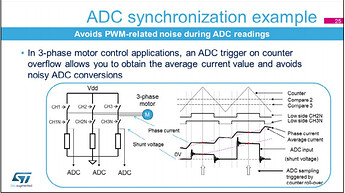
You may be aware of this already but the ADC is suppose to be triggered in the middle of the PWM period (both the one and the off) like in the pg 43 in this pdf.


To debug the ADC sampling you can toggle and IO in DMA1_Channel1_IRQHandler.
This also means that second half of the DMA values are from when no current is following. This is useful to zero out the current (0 current is ~1.65V). Hence the why _readADCVoltage only use the first half of the DMA buffer.

Also I grabbed this code from a MX cube project I didn’t figure out a good way to upload it but if you want it I can figure something out.

Your calculation was very helpful, it would have taken me forever to figure that out. There is one small error, the shunt resistor value is 0.003 ohms instead of 0.03.

I performed some measurements using a shunt resistor value of 0.003 and gain of 64/7, in simpleFOC torque/voltage mode with a stalled motor. I averaged many measurements together using a low pass filter and compared the measurements to those obtained with a cheap multimeter. All measured values are within 0.03 amps, average error 0.014 amps. We can conclude that these parameters result in low bias.

ChgsgKS

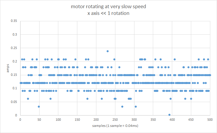
Here is a trace of successive measurements with the motor rotating at a very slow speed:

The error appears to be approximately normally distributed, with a standard deviation about 0.04 amps. The measurement error does not appear to increase when driving more current. This means the percentage error becomes lower as currents become larger.

We can use oversampling to reduce the measurement error. We would have to implement this in software, with ADC_TRIGGEREDMODE_SINGLE_TRIGGER (multiple samples per trigger) the chip is only fast enough for 2x oversampling. ADC_TRIGGEREDMODE_MULTI_TRIGGER doesn’t work for our use case.

I tried modifying the dma interrupt to not trigger during the off duty cycle, but didn’t get anywhere.

2 Likes

Good catch @MotorController
Nice to know the current is calibrated and you seem to be getting some fairly accurate results.
I’m impressed with the consistence of your current measurement. ~0.15A variation is better than I was expecting. Also your plot almost looks like your hitting some kind of quantisation limit is this the case?
When I looked at the current with a scope there did appear to be a bit of ringing so I though that might be the source of the noise however if the measurement are getting more accurate at higher currents this isn’t the case and there’s maybe room for improvement.
In an attempt to improve the consistency of the measurement I increased the sConfig.SamplingTime to ADC_SAMPLETIME_12CYCLES_5; not sure if this was a good idea.
Oversampling might be fun not sure how to go about it if ADC_TRIGGEREDMODE_MULTI_TRIGGER doesn’t work.
Also does your control loop run at the PWM frequency? If not I wonder what would happen if the FIR filter was run in the DMA request. This would greatly increase the number of samples filtered over at-least in my case.

I think the interrupt triggering during the off duty cycle isn’t to much of an issue the only problem I can think of is performance but I doubt is has too much of an impact it’s just something to be aware of.

I did some more measurements. First, I verified that the measurement error was independent of the driving current by calculating the standard deviation of successive measurements. At -0.8A, 0.06A and 0.8A the standard deviation was identical. This confirms the measurement error is a constant.

Then I tested various sample times, from ADC_SAMPLETIME_2CYCLES_5 (fastest) up to ADC_SAMPLETIME_640CYCLES_5 (slowest). Measurement error appears to be the same in all these modes. According to section 4.2.6 the minimum sample time for 12 bits resolution is 9 clock cycles, I’m not sure why we seem to be getting such great accuracy at the fastest possible sample time.

I did some calculations for oversampling. With ADC_TRIGGEREDMODE_SINGLE_TRIGGER , the oversampling is limited by the length of the on-duty cycle. At 25khz and a duty cycle of 10%, this is approximately 1µs. One ADC conversion at the fastest speed takes ~0.25µs (15 clocks at 60Mhz), so at this duty cycle we’re able to get a oversampling of 4x before we run into problems (I verified these measurements with experiments). If the customer decides to use a 50v power supply with a low resistance motor, the timings are completely hopeless. I suggest not to use hardware oversampling.

If we decide to use oversampling, the error scales as expected. 4x oversampling results in log2(3.5) bits of extra information, the theoretical maximum being log2(4).

To clarify why ADC_TRIGGEREDMODE_MULTI_TRIGGER doesn’t work well for our use case, the interrupt triggers in the on-duty cycle as well as the off-duty cycle. During the off-duty cycle there is no useful data but the ADC engine still collects a measurement, this results in more base error. A software implementation can do better.

I see two obvious approaches: implement a low pass filter in the interrupt, as you mentioned. Or increase the DMA buffer size and compute an average of N samples in _readADCVoltage. I’ll pick the one that is simplest to implement. We should keep the oversampling low (i.e. 4) because further filtering can be done with generic simpleFOC code.

My patch for adding b-g431-esc1 to stm32duino has been finally merged. It was held up for 6 months by v2.0 of stm32duino which was released a few days ago.

This means that for those using Arduino IDE - this board will be available for selection under the “DISCO” board variant menu - assuming you’ve updated to use the new board manager url that was introduced for V2.0. I use platformio and that doesn’t support stm32duino V2.0 yet (still on 1.9) - and therefore I’ve not tested whether my changes got translated correctly into the new way stm32duino structures boards. If you are feeling brave, you could give it a go.

You guys have taken this board much further with current control! :boom: There are probably a few patches to the variant to make it simpler to use e.g. enabling opamp by default (as described above).

I’ll probably submit patches for storm32 and vesc_4_12 boards in the coming months to make these boards easier to use too.

3 Likes

I noticed a couple of issues with the current implementation, originating from this comment:

// The DMA of adcBuffer1[2,3] and adcBuffer1[0] are the off duty cycle

It turns out that what’s the on-duty cycle and the off-duty cycle depends on nondeterministic behavior at setup time. Occasionally I can observe [0, 3] and off-duty [1, 2]. I spent all day wresting with timers and I think I figured out how to modify the timer interrupt to only trigger during the on-duty cycle. Like so:

HardwareTimer* _initHardware6PWMInterface(...) {

    HardwareTimer_Handle[index]->handle.Init.RepetitionCounter = 1;

....

  LL_TIM_SetTriggerOutput(HT->getHandle()->Instance, LL_TIM_TRGO_UPDATE);

  HT->pause();
  HT->refresh();

  //Set direction to downcounting
  HT->getHandle()->Instance->CR1 |= TIM_CR1_DIR;
  // Set counter register to max value
  HT->getHandle()->Instance->CNT = TIM1->ARR;

  HT->resume();  
}

The first piece of code sets up the LL_TIM_TRGO_UPDATE to only trigger every second counter overflow or underflow. The second piece of code modifies the center aligned counter to start counting down rather than up.

That’s one part of the problem solved. The second problem is that the order or DMA operations might depend on timer state during setup. Meaning, we’re not sure if pinX belongs to adcBuffer1[0] or adcBuffer1[1]. This requires more investigation, I haven’t been able to reproduce the problem in a controlled environment yet.

Finally, the current readings appear to be inverted. With +3V on the phase A pwm I see a current of -1A. Has anyone reviewed the schematics to see what’s going on here? I suppose we have to invert the current reading in software?

@MotorController
Oh no, I was wondering if it was no deterministic but never saw it changed guess I just got lucky.
Great fix though.
The mxcube setup I feel implies the ADC samples always come in order; but I was wrong before.
I don’t immediately see anything in the schematic that suggests that phase A should be inverted but I just changed the order and sign on the phase until I got what I wanted… so not the most thorough of methods.
@Owen_Williams
Congratulations on getting your changes into master.

Hey congrats, awesome work! I was actually randomly looking at your board manager code over the weekend and saw it had been merged. I wanted to create a board file for the ST-GMBL02V1 board, but in the end it seems to be running fine with the generic F303RET that is also new in 2.0.0 stm32duino.
SimpleFOC compiles and works fine with stm32duino 2.0.0 in Arduino IDE 2.0, and the GMBL02V1 can happily drive 3 motors at up to 8.4V and 1A each. SPI3 is conveniently broken out for attaching your sensors, and there are other pins available for nCS lines, encoders, hall sensors etc. It has single-shunt current sensing, which I’m guessing won’t be supported for a while. I guess I should start a separate thread about it…

As for the current sensing work on the B-G431-ESC1 - that looks really awesome. Will it carry over to other STM chips, or is too specific to that board?

I created a pull request to merge current sensing for the B-G431B-ESC1 into the dev channel: https://github.com/simplefoc/Arduino-FOC/pull/73 comments and tests are welcome. I spent a few days toying with my motors and it has worked well.

You need to have the dev channel, up to (pull request 69) in order to get sensible motor control.

@runger, We may have to modify the pin numbers for other boards with this chip, the current implementation has the ADC channels hardcoded.

2 Likes

Hi Everyone,

I hope it makes sense to put this question into this already existing thread.

I have been experimenting with the B-G431B-ESC1 for a while and wanted to implement InlineCurrentSense on this board.

My setup is:

Arduino IDE
Arduino_Core_STM32 V2.0.0
SimpleFOC Library (I pulled the newest dev branch)
B-G431B-ESC1
AS5600 with I2C
Roxxy BLDC C4240-12

I modified the hardware specific examlpe code to work with my AS5600 Sensor.
My Problem is, that the application stops at the currentSense.init(); command in the setup.

Does anyone have an idea what the problem could be?

This is my Serial Output;

18:11:29.945 → Begin Setup…
18:11:30.020 → Sensor initialized
18:11:30.020 → Linked sensor to motor
18:11:30.020 → Driver initialized
18:11:30.020 → Driver linked

This is my code

#include <SimpleFOC.h>

BLDCMotor motor = BLDCMotor(7);

BLDCDriver6PWM driver = BLDCDriver6PWM(PHASE_UH, PHASE_UL, PHASE_VH, PHASE_VL, PHASE_WH, PHASE_WL);

InlineCurrentSense currentSense = InlineCurrentSense(0.003, -64.0 / 7.0, OP1_OUT, OP2_OUT, OP3_OUT);

MagneticSensorI2C sensor = MagneticSensorI2C(AS5600_I2C);


// angle set point variable
float target_angle = 0;

// instantiate the commander
Commander command = Commander(Serial);
void doTarget(char* cmd) {
  command.scalar(&target_angle, cmd);
}

void setup() {

  Serial.begin(115200);
  Serial.println("Begin Setup..");

  sensor.init();
  Serial.println("Sensor initialized");

  motor.linkSensor(&sensor);
  Serial.println("Linked sensor to motor");

  driver.voltage_power_supply = 12;
  driver.init();
  Serial.println("Driver initialized");

  motor.linkDriver(&driver);
  Serial.println("Driver linked");

  currentSense.init();
  Serial.println("Currentsense initialized");
  
  motor.linkCurrentSense(&currentSense);
  Serial.println("Currentsense linked to motor");


  // aligning voltage [V]
  motor.voltage_sensor_align = 0.2;
  // index search velocity [rad/s]
  motor.velocity_index_search = 3;

  // set motion control loop to be used
  motor.controller = MotionControlType::velocity;

  // contoller configuration
  // default parameters in defaults.h

  // velocity PI controller parameters
  motor.PID_velocity.P = 0.2;
  motor.PID_velocity.I = 20;
  // default voltage_power_supply
  motor.voltage_limit = 1;
  // jerk control using voltage voltage ramp
  // default value is 300 volts per sec  ~ 0.3V per millisecond
  motor.PID_velocity.output_ramp = 1000;

  // velocity low pass filtering time constant
  motor.LPF_velocity.Tf = 0.01;

  // angle P controller
  motor.P_angle.P = 20;
  //  maximal velocity of the position control
  motor.velocity_limit = 4;

  // initialize motor
  motor.init();

  // align encoder and start FOC
  motor.initFOC();

  // add target command T
  command.add('T', doTarget, "target angle");

  Serial.println(F("Motor ready."));
  Serial.println(F("Set the target angle using serial terminal:"));
  _delay(1000);
}


void loop() {

  motor.loopFOC();

  motor.move(target_angle);

  command.run();
}```

i also have the B-G431B-ESC1 . can i use the foc-lib now without a encoder/sensor… i want just use the current sensing (3phase) as a sensor.

if i use 6step open loop velocity control… can i do it without a sensor/encoder? and just apply duty / power per serial command … if not enough power / duty the motor will lose the sync … right… if too much power / duty the motor will burn current and heat up but will stay in sync… right?

Hi @frankers,

You can use open-loop control to move the motor without any sensor, but it won’t be very efficient, i.e. it will use quite a bit more current than closed loop control.

Being “in sync” in open loop mode has to do with the motor following the commutation pattern being set by the software, it doesn’t directly depend on power or duty cycle. The sequence of duty cycles determines the commutation pattern, the frequency of the commutation pattern determines the speed of rotation, and the power used is determined by complex set of factors including motor dynamics, load, phase resistance, voltage limits (=duty cycle limits) set by software and more.

You can’t really use the current sense as a position sensor for closed loop control, its kind of the quantity you’re controlling… and it depends on more things than just the rotor position.

There are (very complex) sensorless position sensing schemes based measuring currents/voltages, but these are dependent on the motor used, and aren’t supported by SimpleFOC. This kind of thing isn’t very “simple” any more :wink:

Hi hasimx,
you have the same configuration like me. Does the board get very warm when you drive the engine slowly? Or is it still cold on closed loop? My board gets I think up to 50°C…
BR - Thomas

I am having the exact same problem, except that I am using hall sensors. Every time I try to implement any form of current sensing the run freezes.

Arduino IDE 1.8.16
Arduino_Core_STM32 V2.2.0
SimpleFOC Library 2.2.2
Board: Discovery → B-G431B-ESC1

Example code:

/**
   B-G431B-ESC1 position motion control example with encoder

*/
#include <SimpleFOC.h>

// Motor instance
BLDCMotor motor = BLDCMotor(7, 0.15, 1550);
BLDCDriver6PWM driver = BLDCDriver6PWM(A_PHASE_UH, A_PHASE_UL, A_PHASE_VH, A_PHASE_VL, A_PHASE_WH, A_PHASE_WL);
LowsideCurrentSense currentSense = LowsideCurrentSense(0.003, -64.0 / 7.0, A_OP1_OUT, A_OP2_OUT, A_OP3_OUT);
//InlineCurrentSense currentSense = InlineCurrentSense(0.003, -64.0/7.0, A_OP1_OUT, A_OP2_OUT, A_OP3_OUT);

// encoder instance
//Encoder encoder = Encoder(A_HALL2, A_HALL3, 2048, A_HALL1);
HallSensor sensor = HallSensor(A_HALL1, A_HALL2, A_HALL3, 7 );

// Interrupt routine intialisation
// channel A, B and C callbacks
void doA() {
  sensor.handleA();
}
void doB() {
  sensor.handleB();
}
void doC() {
  sensor.handleC();
}
//void doA(){encoder.handleA();}
//void doB(){encoder.handleB();}
//void doIndex(){encoder.handleIndex();}

// instantiate the commander
Commander command = Commander(Serial);
//void doTarget(char* cmd) { command.motion(&motor, cmd); }
void onMotor(char* cmd) {
  command.motor(&motor, cmd);
}


/*float target_current = 0;
  // instantiate the commander
  Commander command = Commander(Serial);
  void doTarget(char* cmd) { command.scalar(&target_current, cmd); }*/

// voltage set point variable
float target_voltage = 1;

void doTarget(char* cmd) {
  command.scalar(&target_voltage, cmd);
}

void calcKV(char* cmd) {
  // calculate the KV
  Serial.println(motor.shaft_velocity / motor.target * 30.0f / _PI);

}

void setup() {

  // initialize encoder sensor hardware
  //encoder.init();
  //encoder.enableInterrupts(doA, doB);

  // initialize encoder sensor hardware
  sensor.pullup;
  sensor.init();
  sensor.enableInterrupts(doA, doB, doC);

  // link the motor to the sensor
  //motor.linkSensor(&encoder);

  // link the motor to the sensor
  motor.linkSensor(&sensor);

  // driver config
  // power supply voltage [V]
  driver.voltage_power_supply = 12;
  driver.pwm_frequency = 20000;
  driver.init();
  // link the motor and the driver
  motor.linkDriver(&driver);
  // link current sense and the driver
  currentSense.linkDriver(&driver);

  // current sensing
  currentSense.init();
  // no need for aligning
  currentSense.skip_align = true;
  motor.linkCurrentSense(&currentSense);

  // aligning voltage [V]
  motor.voltage_sensor_align = 3;
  // index search velocity [rad/s]
  motor.velocity_index_search = 3;

  // control loop type and torque mode
  motor.torque_controller = TorqueControlType::voltage;
  motor.controller = MotionControlType::torque;
  motor.motion_downsample = 0.0;

  // velocity loop PID
  motor.PID_velocity.P = 0.1;
  motor.PID_velocity.I = 1.0;
  motor.PID_velocity.D = 0.0;
  motor.PID_velocity.output_ramp = 100.0;
  motor.PID_velocity.limit = 2.0;
  // Low pass filtering time constant
  motor.LPF_velocity.Tf = 0.1;
  // angle loop PID
  motor.P_angle.P = 20.0;
  motor.P_angle.I = 0.0;
  motor.P_angle.D = 0.0;
  motor.P_angle.output_ramp = 0.0;
  motor.P_angle.limit = 50.0;
  // Low pass filtering time constant
  motor.LPF_angle.Tf = 0.0;
  // current q loop PID
  motor.PID_current_q.P = 3.0;
  motor.PID_current_q.I = 300.0;
  motor.PID_current_q.D = 0.0;
  motor.PID_current_q.output_ramp = 100;
  motor.PID_current_q.limit = 6.0;
  // Low pass filtering time constant
  motor.LPF_current_q.Tf = 0.005;
  // current d loop PID
  motor.PID_current_d.P = 3.0;
  motor.PID_current_d.I = 300.0;
  motor.PID_current_d.D = 0.0;
  motor.PID_current_d.output_ramp = 100;
  motor.PID_current_d.limit = 6.0;
  // Low pass filtering time constant
  motor.LPF_current_d.Tf = 0.005;
  // Limits
  motor.velocity_limit = 500.0;
  motor.voltage_limit = 6.0;
  motor.current_limit = 2.0;
  // sensor zero offset - home position
  motor.sensor_offset = 0.0;
  // general settings
  // motor phase resistance
  motor.phase_resistance = 0.15;
  // pwm modulation settings
  motor.foc_modulation = FOCModulationType::SinePWM;
  motor.modulation_centered = 1.0;


  // use monitoring with serial
  Serial.begin(115200);
  // comment out if not needed
  motor.useMonitoring(Serial);

  // initialize motor
  motor.init();
  // align encoder and start FOC
  motor.initFOC(0.0, Direction::CCW);

  // set the inital target value
  //motor.target = 1;


  // add target command T
  //command.add('T', doTarget, "target angle");
  // define the motor id
  //command.add('T', doTarget, "target current");
  command.add('A', onMotor, "motor");

  //Serial.println(F("Motor ready."));
  //Serial.println(F("Set the target angle using serial terminal:"));

  // Run user commands to configure and the motor (find the full command list in docs.simplefoc.com)
  Serial.println(F("Motor commands sketch | Initial motion control > torque/voltage : target 2V."));
  // add target command T
  command.add('T', doTarget, "target voltage");
  command.add('K', calcKV, "calculate KV rating");

  Serial.println(F("Motor ready."));
  Serial.println(F("Set the target voltage : - commnad T"));
  Serial.println(F("Calculate the motor KV : - command K"));
  _delay(1000);
}

void loop() {
  // main FOC algorithm function

  // iterative setting FOC phase voltage
  motor.loopFOC();

  // Motion control function
  //motor.move();
  motor.move(target_voltage);
  // motor.move(target_current);
  //Serial.println("test");
  // function intended to be used with serial plotter to monitor motor variables
  // significantly slowing the execution down!!!!
  //motor.monitor();

  // user communication
  command.run();

  //PhaseCurrent_s currents = currentSense.getPhaseCurrents();
  //float current_magnitude = currentSense.getDCCurrent();

  //Serial.print(currents.a*1000); // milli Amps
  //Serial.print("\t");
  //Serial.print(currents.b*1000); // milli Amps
  // Serial.print("\t");
  //Serial.println(currents.c*1000); // milli Amps
  //Serial.print("\t");
  //Serial.println(current_magnitude*1000); // milli Amps
}

Cheers!

I can confirm something is broken, it appears current sense timers fail to initialize. Will report back later.

Edit: I tested that a random older commit (9451d96) works, you can use that in the meantime.

Edit: The most recent commit that works is 401ebe9.

Edit: I have the code back in working state, but it looks like there is a significant regression in terms of power consumption. Will need more days to investigate.

1 Like

Thanks I will give it a shot :wink:

Edit: I think the problem was also discovered in this post? Seems he came close to the root of the issue?

Edit 2: I found another thread regarding the same issue:

I was able to track down the problem as follows:

In 0066b5e the timer code was refactored. This broke (reasons unclear) the synchronization between the pwm timers and the inline current sense DMA, causing the DMA to trigger in the pwm trough instead of the peak.

In 37e1a73 and bdc95910 code intended for DMA timer synchronization was removed. Since these commits, the current sense returns no data instead of faulty data, the code detects this but then locks up due to a faulty debug print. I believe this is the issue spotted by the threads you linked.

I’m trying to restore the pwm/DMA synchronization, but no luck so far… The documentation clearly states how timers should be synchronized, but the procedure outlined doesn’t work. With a few dirty hacks I’m able to restore functionality, those hacks don’t work reliably due to race conditions, but at least I was able to verify that this is the only problem left.

Edit: I fixed all problems, will submit a patch later.

1 Like

Patch here: B g431 b current sense fixes by sDessens · Pull Request #210 · simplefoc/Arduino-FOC · GitHub

1 Like

Thanks for the speedy fix! :smiley:

Slight update. It turns out that InlineCurrentSense does not work on this board, what we really did was implement low side current sense in the InlineCurrentSense class.

Only LowsideCurrentSense is supported on this board, the pull request above has been rebased to reflect this change.

1 Like