Nice! I have thought many times that one of the main issues with this board is the lack of SPI. This is a good workaround for now. However at the risk of sounding like a broken record, I wan to say again that the long term solution for such issues is IMO a next gen flagship board such as the QUADVRANS, or the Lepton G4 which is in the works. And by that I mean at least one additional revision after testing or modification of those boards.
This board has many downsides, notably you cannot actually use it in a product for sale. It costs way more to make than they sell it for. It also has some baffling issues with overheating, as well as obvious issues that are described in thread with insufficient pins broken out, very hard to access and so on. Also we don’t really need the ST-link to be built in.
However it’s a good processor and I never had noise issues with it. I did a number of times have it overheat on me when it wasn’t even doing anything, I think that was because of the high density of the board and minor intermittent faults with my soldering due to the very high difficulty of doing it right…
Yet another simple mod of the B-G431B-ESC1: If you need another analog input, you can easily desolder the potentiometer and use the center pin. I do so to attach an NTC for measureing the motor temperature. To desolder the part, simply place a small flat screwdriver between the board and the potentiometer, then desolder the pins step by step while you issue gentle force with the screw driver. Work slow, pull each pin out just a little bit, then the next and so on. After three rounds or so, the potentiometer will fall off.
You will have to forgive me, as it is not often that I delve into hardware like this until recently. I would just like to try and get a bit of clarification on I2C usage.
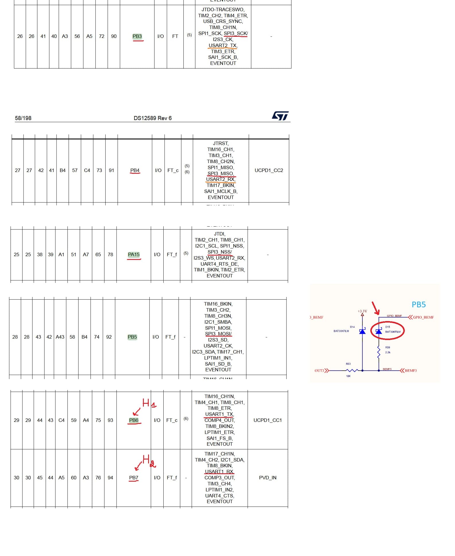
If I would like to use I2C, I need to use the following 4 pins?
In addition to that, I need to use pull-up resistors? Which wires require these resistors? If I were to acquire them, I would search for 4.7k resistor? (If I were to get this, it has a number of 4.7k resistors, which I assume are what I need?)
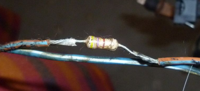
If both of those things are true, I then take the wire I already soldered to those pins, and solder the resistor inline of the particular wires that require them?
(For illustrative purposes only, I just looked for the first example, so I could make sure I am understanding the requirements properly, and is not representative of the actual resistor I would need.)
So then once that is in place (on whichever wires require them), I then need to make the code modifications from the first post, (Ex: replacing PeripheralPins.c, PinNamesVar.h, etc, etc), but not use the 3 (PIO__) build flags from the first post, but instead use the build flags of:
build_flags =
    -D PIN_WIRE_SDA=PB7
    -D PIN_WIRE_SCL=PB8
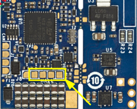
and make the additional code changes for the I2C1_SDA, and I2C1_SCL to use PB7-8 (which are then the two left most pins of the 4 in the above square section in the image I highlighted).
Once those things are done, that should be it?
Again, sorry for having to ask what are probably silly questions to most in this thread. I just want to make sure I am doing things the right way.
Thanks,
-MH
No, I didn’t. I suppose that is certainly worth a go, though. I spend so much time browsing here, I forgot all about Discord.
Edit: I was able to get it working without any additional work other than using the 4 pins I soldered highlighted in my image above. (no resistors)
Hi I’ve also been trying to work with the B-G431B-ESC1 can you share me your platform.ini file. that would be really helpful @MostHated
Sure thing, here is the relevant sections that I use:
For build flags, most of those are just things I use in my own code, the only one you would really need is HAL_OPAMP_MODULE_ENABLED.
[power]
supply=24

[common]
lib_archive = false
monitor_speed = 115200
lib_deps =
	askuric/Simple FOC@^2.3.3
build_flags =
  -D POWER_SUPPLY=${power.supply}
  -D MONITOR_SPEED=115200

[disco_b_g431b_esc1]
platform = ststm32
framework = arduino
board = disco_b_g431b_esc1
debug_tool = stlink
upload_protocol = stlink
lib_archive = ${common.lib_archive}
monitor_speed = ${common.monitor_speed}
lib_deps =
  ${common.lib_deps}

[env:b_g431b_esc1_gbm5]
extends = disco_b_g431b_esc1
build_flags =
  ${common.build_flags}
  -D GBM520875T
  -D MOTOR='GBM520875T'
  -D POLE_PAIRS=11
  -D VOLTAGE_LIMIT=6
  -D HAL_OPAMP_MODULE_ENABLED
have you tried the position control example code does it work for you?
Hello,
as some of you, I am interested by the b-g431b-esc1 board to power a BLDC motor.
But I read that the first revision of this board had a design flaw (regarding a via) preventing it to be used with high currents.
I know that a new version has been released but it is not sure that the problem has been solved.
So, I would like to know if someone here has successfully tested the last version under heavy load (30-40A).
Thank you!
Guys the QVADRANS is going to be way better than this board for the purposes you seem to be discussing, cheaper, easier to use, got the pins you want right there, no need to get in there with a microscope and surgeon’s hands. It’s cheaper, too.
Thanks for pointing me this project, but it seems to be in alpha stage, right?
And, unfortunately, the FETs are way too weak for my needs.
A cheaper alternative to the VESC6 EDU would be perfect!
On the ESC1 you will need excessive active cooling if you want to operate it at 30A. Without that you are limited to something like 10A or so (that‘s a guess, I use it with little cooling at max 10A and it stays below 50C). Its biggest problem however is the power supply, which must never exceed the specs, also not in the presence of BEMF. Apart from that, it is an impressive board.
Ya, according to some posts on ST forum, it seems that the ESC1 last rev still have PCB issues. Too bad…
I had a quick look at the PCB files in Altium and couldn’t see any obvious issues. What are the issues you are talking about? A link would be helpful.
Mentioned here.
Whoever posted that thread did not look very carefully. Whoever replied must also be very clueless about the board design.
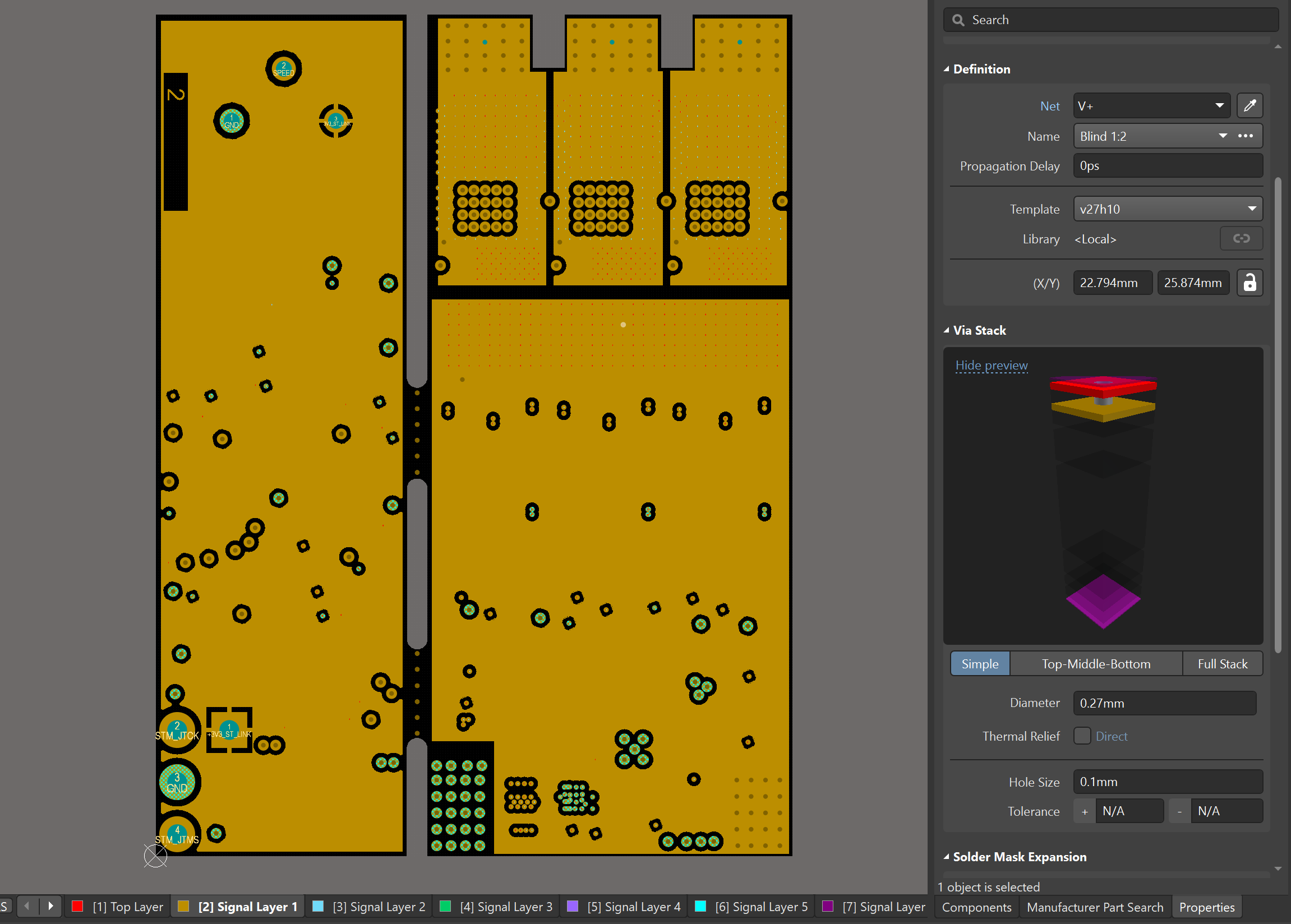
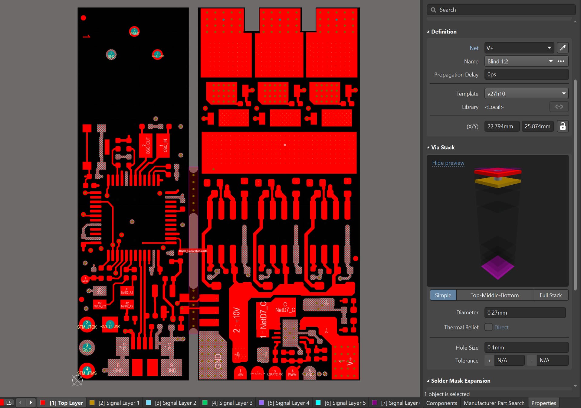
V+ from the top layer is connected to inner layer 2 (V+ plane) by hundreds of microvias. They have a hole size of 0.1mm.
Honestly this board design seems very good and it is what I am aiming to achieve, however producing 2+N+2 HDI costs way too much. The QVADRANS will never be able to compete with this in my opinion.
Thank you for the board review Andrew.
Nevertheless, the board doesn’t seem to reach the rated specs.
That is why I asked my question. Looking for someone who really pushed the board to its limits (40A with air cooling).
I did with liquid cooling (Fluorinert).
You can find my pics somewhere around/above in this thread.
I very strongly recommend against doing this in a hobby environment.
Cheers,
Valentine