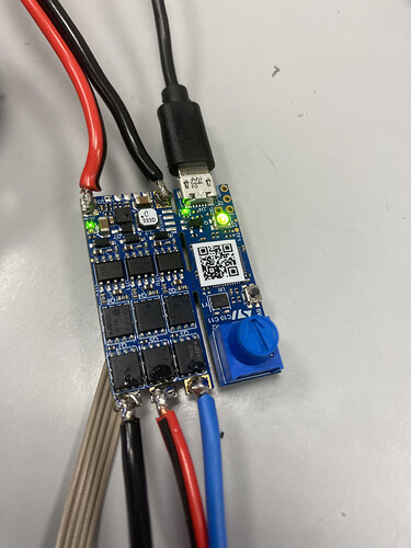
B-G431B-ESC1: Beginner guide + I2C guide

The first revision of the board four years ago had a big issue where the designer missed all vias but one from one of the fets. They fixed it and ST removed all links, and deleted all schematics, they were too embarrassed. Some of the early boards however are still in circulation sold by some distributors.

Cheers,
Valentine

@Andrew

Please see the ST response. I don’t believe ST’s engineers are clueless, but mistakes happen in production all the time. Please be polite and considerate to other members of the community.

Cheers,
Valentine

1 Like

When I look at the board revision history it mentioned nothing about the early versions of the board having limitations in the maximum current, which is why I assumed that the information provided in the ST forums was incorrect. I think you might be right in the theory that ST was too embarrassed.


2 Likes

That’s pretty awesome!

So you get 1Nm stall torque from the esc.

With 1/10 reduction that’s 10Nm, which is really, really good.

Cheers,
Valentine

That’s not me I just came across this video.
It shows the thermal limits of this board at 20a with dome cooling.

I was wondering how you got that accent… but decided to keep my mouth shut.

Cheers,
Valenine

1 Like

The qvadrans will never be able to compete how?

We were tossing around the idea of making things so the copper areas to and from the mosfets could be flooded with solder, that might turn out to be a good trick to increase current carrying capacity.

But I’ve bought 10 B-G431-ESC1 boards now and used them a fair bit and it really has a lot of issues. There are quality control issues, there is overheating, there are usability and licensing issues, the current measurement signal to noise ratio seems poor, It’s still the best choice among other existing currently easy to get boards, and any design may have at least a few strengths over another.

However, I think the qvadrans will be much better yet also cheaper for 95% of the uses people seem to be pursuing in this board, and if you want to change the design to make it better in some way that you really need, it’s going to be a lot easier than it is for the B-G431-ESC1 board.

Hi everyone,
I’m testing the G431B‑ESC1 board. Using STM32duino from the Arduino IDE, I’ve tried a few basic things (serial communication, reading the onboard potentiometer and writing its value, etc.), and they work well — just like on an Arduino.

Now I’m about to test a motor using the B_G431B_ESC1.ino example provided in the SimpleFOC library.
This example allows using an encoder like the AMT103, connected to pins PA6, PA7, and PA8, which are available on the J8 connector.

If I wanted to use an AS5600 encoder instead (I2C), which pins would be SDA and SCL? Are they the same as those indicated by Ultra.robotics — namely, PA7 (SDA) and PA8 (SCL)?
And if I create an I2C encoder instance, will it automatically use those pins (PA7, PA8)?

Thank you all!!!

Hi everyone,
I tried the B-G431B-ESC1 board but it doesn’t work… I tested the example provided with the library, but it doesn’t function — the motor doesn’t even initialize.
Then I tried the code suggested by Valentine… that doesn’t work either.
If I try reading the potentiometer on pin PB12, it works… it also reads an AMT103 encoder on pins hall1 and hall2.
But with Valentine’s code, the motor shows no signs of life.
What could be the cause?

this is the code

#include <SimpleFOC.h>

// NUMBER OF POLE PAIRS, NOT POLES

BLDCMotor motor = BLDCMotor(14);

// MUST USE 6PWM FOR B-G431 DRIVER

BLDCDriver6PWM driver = BLDCDriver6PWM(A_PHASE_UH, A_PHASE_UL, A_PHASE_VH, A_PHASE_VL, A_PHASE_WH, A_PHASE_WL);

void setup() {

// driver config

// power supply voltage [V]

driver.voltage_power_supply = 12;

driver.init();

// link the motor and the driver

motor.linkDriver(&driver);

// limiting motor movements

motor.voltage_limit = 3; // [V]

motor.velocity_limit = 1024; // [rad/s]

// open loop control config

motor.controller = MotionControlType::velocity_openloop;

// init motor hardware

motor.init();

}

void loop() {

motor.move(analogRead(PB12));

}

The motor is a 5010 360 KV with a 1.2 Ohm phase to phase resistance. I use a power supply with 12 V.. the motor is free to move.