300 rads per second top speed, the only noise it makes is the blade noise. The motor and electronics and bearings should be genuinely silent.
Hey @ultra.robotics, I was just trying to upload a sketch but then i got following error code.
Sketch uses 58340 bytes (44%) of program storage space. Maximum is 131072 bytes.
Global variables use 3480 bytes (10%) of dynamic memory, leaving 29288 bytes for local variables. Maximum is 32768 bytes.
-------------------------------------------------------------------
STM32CubeProgrammer v2.14.0
-------------------------------------------------------------------
Error: No debug probe detected.
Failed uploading: uploading error: exit status 1
I also can’t get a connection in the STM32 Cube Programmer.
Do you have a idea what the issue could be ?
Thanks in advance
How are you programming it?
Do you have the STLINK (the breakaway board) connected?
That’s what it says when it’s not connected, there could be some other error mimicking it.
I am using Arduino IDE and yes the STLINK is connected.
Do you have an Idea where should start looking for errors ?
I Cant even get a connection when i want to update the firmware via the st-linkupgrade.exe
If even the stlink tool is not finding it, then something is pretty wrong.
Can you try a different usb cable?
Do you see it at all in the Windows device manager?
I like to use hall sensors and AS5047/AS5048 together:
https://community.simplefoc.com/t/b-g431b-esc1-beginner-guide-i2c-guide/515/89?u=wimalopaan
But I see soem problems:
https://community.simplefoc.com/t/b-g431-esc-and-as5047-as5048/4027/3?u=wimalopaan
Any other ideas?
I think instead of the ESC1 you should use a different controller, probably.
Mmh, yes, probably.
My preferred MCU would be indeed the g431. I was looking around, but did not find anything (aside from VESC).
Do you have any suggestions?
You could try just a G431 nucleo, and put something like the SimpleFOC shield on, or something similar.
I don’t know how well the timer pins work out on the shield on Nucleo since it’s designed for an Arduino Uno but I’m under the impression some people have got it working before.
Or: pick a sensor which works on I2C as you might not have the same pin conflicts on the G431. How tied into those sensors are you?
Well, I think I will go with the IFX007 board.
I2C is too slow, SPI should be fast enough.
There is an effort underway to produce a good board based on this chip, for use I think, if I may insert my opinion, as a flagship board for simplefoc type stuff. But I haven’t and don’t think I will have time to do much on it for a while now.
Are there already any docs for this planned board available?
nope still more work to do on it. Always lots to do and very few or no people who want to or are willing to/ have time to do it…
Do you mean the QVADRANS?
That board is one additional step yes, but it needs testing and possibly some changes, it is not clear.
I’ve got a batch of those boards in hand and seemingly fully functional. I haven’t tested SPI yet, but UART works and I can spin a low-power gimbal motor using an AS5600 encoder without any problems. It might be a second before I get to testing more than that though since my immediate projects don’t need more than that
SPI modification more detailed steps (hopefully):
Tested the board with small drone motors, usually they have phase resistance of 0.1ohm, close loop control didn’t work using I2C AS5600 sensor. So i tried to modify the board for SPI to use AS5048A, i followed steps above from @Magneon and @Grizzly, and i succeeded, closed-loop control got to work perfectly. hardware modification part is not so hard, but you need some good soldering skills, the only hard part is connecting a wire to an SMD diode, but only if you want full SPI (read and write) you can make sure first that your sensor support read-only SPI with Arduino. those are the steps in more detail:
Theory:
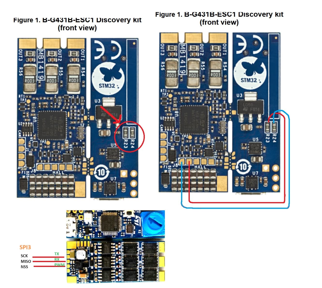
from G431 mcu datasheet, we can see that PB4, PB3 which are used for Serial (USART2), and are easily accessible from TX, RX board pads, can be used also as SPI3_MISO, SPI3_SCK. while PA_15 which is used as PWM input, and easily accessible from PWM board pad, could be used as SPI3_NSS, also, PB5 which is used for back emf reading purposes (which is usually not necessary for SimpleFoc usage), could be used as SPI3_MOSI. but the easiest way to access it is by soldering a wire to D15 cathode.
the board allows to disconnect PB4, PB3 from serial and free them by removing the two zero ohm resistors R23, R24. To enable Serial again, we will use USART1 instead, as its pins PB6, PB7 are easily accessible from sensor board pads H1, H2. so we want to connect H1, H2 to R23, R24 pads and redefine pins configuration in board software files
LEVEL 1: read-only SPI, Serial disabled:
Hardware:
remove the zero ohm resistors R23, R24
use board pads UART TX, UART RX, PWM as SCK, MISO, NSS respectively
set MOSI pin from sensor to VCC
note that output from board pads (TX, RX, PWM) are 3.3v level
Software:
this step is missed in @Grizzly explanation above, didn’t work without it for me.
In ……\variants\STM32G4xx\G431C(6-8-B)U_G441CBU\PeripheralPins_B_G431B_ESC1.c, uncomment and edit as the following:
                //*** SPI ***

                #ifdef HAL_SPI_MODULE_ENABLED
                WEAK const PinMap PinMap_SPI_MOSI[] = {
                // {PA_7,      SPI1, STM_PIN_DATA(STM_MODE_AF_PP, GPIO_PULLUP, GPIO_AF5_SPI1)},
                // {PA_11,     SPI2, STM_PIN_DATA(STM_MODE_AF_PP, GPIO_PULLUP, GPIO_AF5_SPI2)},
                // {PB_5,      SPI1, STM_PIN_DATA(STM_MODE_AF_PP, GPIO_PULLUP, GPIO_AF5_SPI1)},
                // {PB_5_ALT1, SPI3, STM_PIN_DATA(STM_MODE_AF_PP, GPIO_PULLUP, GPIO_AF6_SPI3)},
                {PB_5, SPI3, STM_PIN_DATA(STM_MODE_AF_PP, GPIO_PULLUP, GPIO_AF6_SPI3)},
                // {PB_15,     SPI2, STM_PIN_DATA(STM_MODE_AF_PP, GPIO_PULLUP, GPIO_AF5_SPI2)},
                {NC,        NP,   0}
                };
                #endif

                #ifdef HAL_SPI_MODULE_ENABLED
                WEAK const PinMap PinMap_SPI_MISO[] = {
                // {PA_6,      SPI1, STM_PIN_DATA(STM_MODE_AF_PP, GPIO_PULLUP, GPIO_AF5_SPI1)},
                // {PA_10,     SPI2, STM_PIN_DATA(STM_MODE_AF_PP, GPIO_PULLUP, GPIO_AF5_SPI2)},
                // {PB_4,      SPI1, STM_PIN_DATA(STM_MODE_AF_PP, GPIO_PULLUP, GPIO_AF5_SPI1)},
                // {PB_4_ALT1, SPI3, STM_PIN_DATA(STM_MODE_AF_PP, GPIO_PULLUP, GPIO_AF6_SPI3)},
                {PB_4, SPI3, STM_PIN_DATA(STM_MODE_AF_PP, GPIO_PULLUP, GPIO_AF6_SPI3)},
                // {PB_14,     SPI2, STM_PIN_DATA(STM_MODE_AF_PP, GPIO_PULLUP, GPIO_AF5_SPI2)},
                // {PC_11,     SPI3, STM_PIN_DATA(STM_MODE_AF_PP, GPIO_PULLUP, GPIO_AF6_SPI3)},
                {NC,        NP,   0}
                };
                #endif

                #ifdef HAL_SPI_MODULE_ENABLED
                WEAK const PinMap PinMap_SPI_SCLK[] = {
                // {PA_5,      SPI1, STM_PIN_DATA(STM_MODE_AF_PP, GPIO_PULLUP, GPIO_AF5_SPI1)},
                // {PB_3,      SPI1, STM_PIN_DATA(STM_MODE_AF_PP, GPIO_PULLUP, GPIO_AF5_SPI1)},
                // {PB_3_ALT1, SPI3, STM_PIN_DATA(STM_MODE_AF_PP, GPIO_PULLUP, GPIO_AF6_SPI3)},
                {PB_3, SPI3, STM_PIN_DATA(STM_MODE_AF_PP, GPIO_PULLUP, GPIO_AF6_SPI3)},
                // {PB_13,     SPI2, STM_PIN_DATA(STM_MODE_AF_PP, GPIO_PULLUP, GPIO_AF5_SPI2)},
                // {PC_10,     SPI3, STM_PIN_DATA(STM_MODE_AF_PP, GPIO_PULLUP, GPIO_AF6_SPI3)},
                // {PF_1,      SPI2, STM_PIN_DATA(STM_MODE_AF_PP, GPIO_PULLUP, GPIO_AF5_SPI2)},
                {NC,        NP,   0}
                };
                #endif

                #ifdef HAL_SPI_MODULE_ENABLED
                WEAK const PinMap PinMap_SPI_SSEL[] = {
                // {PA_4,      SPI1, STM_PIN_DATA(STM_MODE_AF_PP, GPIO_PULLUP, GPIO_AF5_SPI1)},
                // {PA_4_ALT1, SPI3, STM_PIN_DATA(STM_MODE_AF_PP, GPIO_PULLUP, GPIO_AF6_SPI3)},
                // {PA_15,     SPI1, STM_PIN_DATA(STM_MODE_AF_PP, GPIO_PULLUP, GPIO_AF5_SPI1)},
                // {PA_15_ALT1,SPI3, STM_PIN_DATA(STM_MODE_AF_PP, GPIO_PULLUP, GPIO_AF6_SPI3)},
                {PA_15, SPI3, STM_PIN_DATA(STM_MODE_AF_PP, GPIO_PULLUP, GPIO_AF6_SPI3)},
                // {PB_12,     SPI2, STM_PIN_DATA(STM_MODE_AF_PP, GPIO_PULLUP, GPIO_AF5_SPI2)},
                // {PF_0,      SPI2, STM_PIN_DATA(STM_MODE_AF_PP, GPIO_PULLUP, GPIO_AF5_SPI2)},
                {NC,         NP,   0}
                };
                #endif
Notes:
MOSI needs to be set in PinMap to something for SPI to work. At least for me, it didn’t work without it.
when initing sensor, set the SPIClass parameter to SPI3, using:
SPIClass SPI_3(PB5, PB4, PB3); // MOSI, MISO, CLK
            sensor.init(&SPI_3);
you are asked to set CSN when creating the sensor object, like:
MagneticSensorAS5048A sensor = MagneticSensorAS5048A(PA15);
try SimpleFOCDrivers sensor implementation (like MagneticSensorAS5048A) if SimpleFOC one didn’t work (you read only zeros)
tip: use segger rtt for debugging and monitoring in place of the disabled Serial, check:
https://community.simplefoc.com/t/use-of-segger-rtt-for-monitoring/3192
LEVEL 2: get Serial working, but can’t use H1, H2, H3 for sensor (which are used for ABI, I2C, hall sensors):
Hardware:
connect R23, R24 pads (top ones on the image, or ones away from usb) to H2, H1, respectively
Soldering tips:
you better start by hot glueing the wire and fixing it close to the pad, and then solder them
use silver plated wires
Software:
In file …..\variants\STM32G4xx\G431C(6-8-B)U_G441CBU\variant_B_G431B_ESC1.h, find SERIAL_UART_INSTANCE, and change as following:
            #define SERIAL_UART_INSTANCE    1 //Connected to ST-Link
            // Default pin used for 'Serial' instance (ex: ST-Link)
            // Mandatory for Firmata
            #ifndef PIN_SERIAL_RX
            #define PIN_SERIAL_RX         PB7   // PB4
            #endif
            #ifndef PIN_SERIAL_TX
            #define PIN_SERIAL_TX         PB6   // PB3
            #endif

            In ……\variants\STM32G4xx\G431C(6-8-B)U_G441CBU\PeripheralPins_B_G431B_ESC1.c Add our UART pins UART PinMap:
            #ifdef HAL_UART_MODULE_ENABLED
            WEAK const PinMap PinMap_UART_TX[] = {
            //  {PA_2,      LPUART1, STM_PIN_DATA(STM_MODE_AF_PP, GPIO_PULLUP, GPIO_AF12_LPUART1)},
            //  {PA_2_ALT1, USART2,  STM_PIN_DATA(STM_MODE_AF_PP, GPIO_PULLUP, GPIO_AF7_USART2)},
            //  {PA_9,      USART1,  STM_PIN_DATA(STM_MODE_AF_PP, GPIO_PULLUP, GPIO_AF7_USART1)},
            //  {PA_14,     USART2,  STM_PIN_DATA(STM_MODE_AF_PP, GPIO_PULLUP, GPIO_AF7_USART2)},
            {PB_3,      USART2,  STM_PIN_DATA(STM_MODE_AF_PP, GPIO_PULLUP, GPIO_AF7_USART2)},
            {PB_6,      USART1,  STM_PIN_DATA(STM_MODE_AF_PP, GPIO_PULLUP, GPIO_AF7_USART1)},
            //  {PB_9,      USART3,  STM_PIN_DATA(STM_MODE_AF_PP, GPIO_PULLUP, GPIO_AF7_USART3)},
            //  {PB_10,     USART3,  STM_PIN_DATA(STM_MODE_AF_PP, GPIO_PULLUP, GPIO_AF7_USART3)},
            //  {PB_11,     LPUART1, STM_PIN_DATA(STM_MODE_AF_PP, GPIO_PULLUP, GPIO_AF8_LPUART1)},
            //  {PC_4,      USART1,  STM_PIN_DATA(STM_MODE_AF_PP, GPIO_PULLUP, GPIO_AF7_USART1)},
            //  {PC_10,     USART3,  STM_PIN_DATA(STM_MODE_AF_PP, GPIO_PULLUP, GPIO_AF7_USART3)},
            //  {NC,        NP,      0}
            };

            #ifdef HAL_UART_MODULE_ENABLED
            WEAK const PinMap PinMap_UART_RX[] = {
            //  {PA_3,      LPUART1, STM_PIN_DATA(STM_MODE_AF_PP, GPIO_PULLUP, GPIO_AF12_LPUART1)},
            //  {PA_3_ALT1, USART2,  STM_PIN_DATA(STM_MODE_AF_PP, GPIO_PULLUP, GPIO_AF7_USART2)},
            //  {PA_10,     USART1,  STM_PIN_DATA(STM_MODE_AF_PP, GPIO_PULLUP, GPIO_AF7_USART1)},
            //  {PA_15,     USART2,  STM_PIN_DATA(STM_MODE_AF_PP, GPIO_PULLUP, GPIO_AF7_USART2)},
            {PB_4,          USART2,  STM_PIN_DATA(STM_MODE_AF_PP, GPIO_PULLUP, GPIO_AF7_USART2)},
            {PB_7,      USART1,  STM_PIN_DATA(STM_MODE_AF_PP, GPIO_PULLUP, GPIO_AF7_USART1)},
            //  {PB_8,      USART3,  STM_PIN_DATA(STM_MODE_AF_PP, GPIO_PULLUP, GPIO_AF7_USART3)},
            //  {PB_10,     LPUART1, STM_PIN_DATA(STM_MODE_AF_PP, GPIO_PULLUP, GPIO_AF8_LPUART1)},
            //  {PB_11,     USART3,  STM_PIN_DATA(STM_MODE_AF_PP, GPIO_PULLUP, GPIO_AF7_USART3)},
            //  {PC_11,     USART3,  STM_PIN_DATA(STM_MODE_AF_PP, GPIO_PULLUP, GPIO_AF7_USART3)},
            {NC,        NP,      0}
            };
            #endif
LEVEL 3: get full SPI
Hardware:
solder a wire to D15 cathode as in the image

Software:
follow @Grizzly explanation: B-G431B-ESC1: Beginner guide + I2C guide - #90 by Grizzly
sorry, I prepared more demonstrating images but can’t post them as the forum doesn’t allow new users to post more than one media file