They don’t call them Micro-Electronics for no reason, that’s some snug soldering!
Looking forward to what you find out (hopefully it doesn’t knock out the temp sensor or anything)
They don’t call them Micro-Electronics for no reason, that’s some snug soldering!
Looking forward to what you find out (hopefully it doesn’t knock out the temp sensor or anything)
I’ve got SPI3 wired up, minus MOSI (which is otherwise occupied). The pins I used were the button and CAN disable (PC10+11) which are SPI3 CS and MISO, with the PWM input pin as CS, as well as 3.3V and gnd. The AS5047 can run in unidirectional mode (MISO only), but so far the Arduino core’s SPI implementation is hanging on clocking out the SPI data (possibly since it isn’t configured for unidirectional SPI). The other possibility is that the button’s de-bounce or pull-up passives are mucking with SCK, but I’ll dive into that tonight (or whenever I get back to this) with an oscilloscope and logic analyzer to double check the IOs, and then probably a direct stm32 LL SPI function to get to the bottom of things.
You have amazing soldering skills! What you did there requires far more than just good tools. You should channge your nickname to something like GodOfSoldering.
Time will tell if it was enough. I do have to recommend watching youtube videos on PCB trace repair (they do some truly crazy stuff), and making frequent use of IPA wash, dry, flux, do one thing, then repeat. Getting the two tiny leads tinned and soldered took a half dozen tries, and 2-3 bridges and repairs. My setup is better than most amateurs, but not super expensive ($50 hakko soldering station, $30 USB microscope, a $2 14x14" ceramic floor tile, a variety of very cheap soldering tips, and most importantly a lot of patience and creative hand bracing since at this scale even the steadiest hands are too shaky). Dollar store clear epoxy as well, instead of proper UV cure solder mask. Don’t tell the actual electrical people at my work ![]()
OK… SPI guide (not very beginner friendly ![]() )
)
The stm32g431cb has 3 SPI ports (spi1/2/3).
I wanted to see if it was possible to expose one of them to hook up an as5047 SPI encoder.
What do we need? Well, as per some versions of its data sheet, the as5047 can run in two modes:
This means that in theory, all we need from the SPI port is SCK, and MISO. The CS pin can be done manually using any old GPIO, and MOSI in theory isn’t needed at all in this unidirectional mode.
Focusing first just on MISO and SCK in the stm32g431cb datasheet, and crossreferencing the pin allocation in um2516 (the B-G431B-ESC1 user manual):
I face the choice: Sacrifice CAN+the button, which I’m not planning on using (by repurposing CAN_SHDN and the button input) for SPI3, or get rid of USART2, which I was planning on using for debugging unlocking either SPI1 or 3.
I decided that SPI3 via PC10/11 was the best choice.
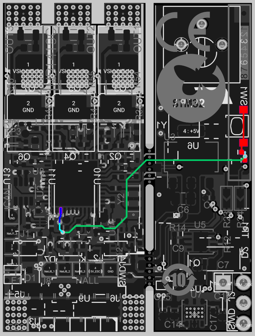
I loaded the board files from ST’s website onto the free Online PCB Viewer to Visualize and Share Electronics Design Projects | Altium 365 Viewer to look through the traces.
PC11 (our new SPI_MISO) is exposed on the bottom layer here (in dark blue):
This brings us to our problem pin, PC10.
This is where things got dicey.
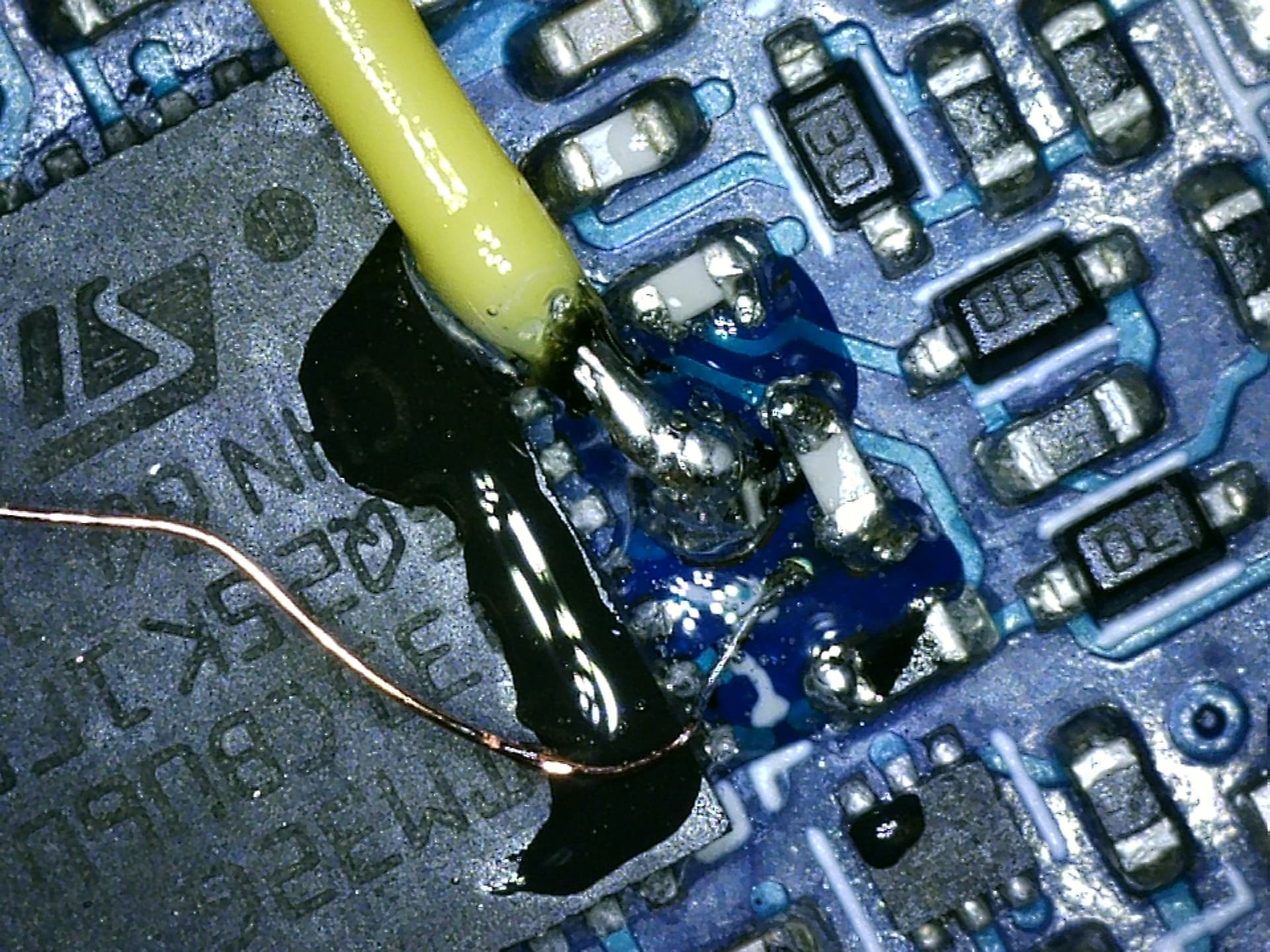
I used needle point tweezers to gently scrape the solder mask off above the via (viewing through a cheap USB microscope), then used (IPA scrub->flux->reapply solder) more or less in a loop 5-6 times until it worked and had a decent tin coating on both the TP2 pad, and the revealed via beside it, without any solder bridges.
Once things were tinned, applied pre-tinned the yellow 28 gauge wire to the test point (PA10), and the copper 38 gauge enameled wire to the tinned via. I then tested continuity with my multimeter (and microscope) to verify things seemed OK, and then coated the connections with a bit of clear epoxy.
Once the epoxy cured, I cut the magnet wire down to ~1cm, stripped it a bit, and soldered blue 28 gauge wire to it. I then heat-shrunk the blue and yellow wires together to provide strain relief.,
Before:
After:
The top side is much simpler:
We now have all 5 wires needed for unidirectional SPI!
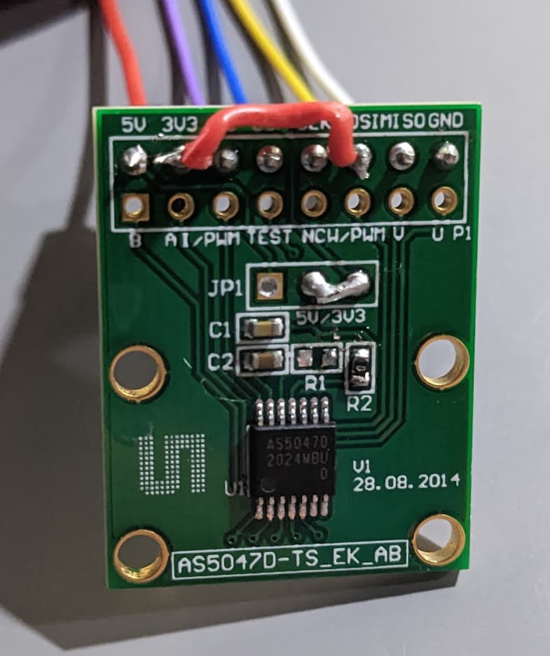
Back to nice 0.1" pitch stuff!
I wanted to run everything on 3.3V, which meant jumping the 5V and 3V3 pins in JP1 (why are there pre-populated headers on the wrong side!), so desoldered the headers with ceramic tweezers that made pulling the pins out super easy without wicking heat from them, and then re-soldered a bit of one of the pins as a jumper.
R1 needed to be moved to R2 as part of 3.3V mode (not sure why they have jumpers if you need to resolder resistors too…)
3V3 needed a jumper wire to MOSI to enable unidirectional mode on the AS5047 (red wire)
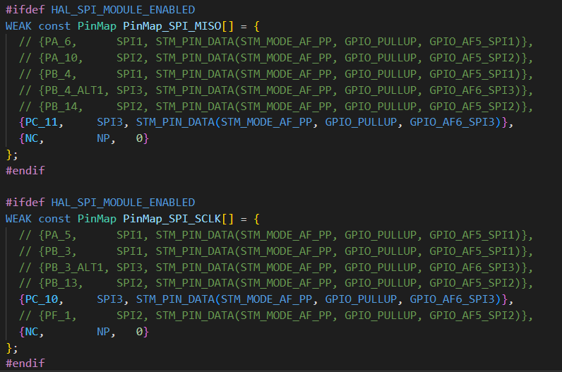
You need to update C:\Users\ your_username \.platformio\packages\framework-arduinoststm32\variants\STM32G4xx\G431C(6-8-B)U_G441CBU\PeripheralPins_B_G431B_ESC1.c (or equivalent arduino location):
Only HAL_SPI_MODULE_ENABLED is super important here, but I’m including it all for completeness.
[env:disco_b_g431b_esc1]
platform = ststm32
board = disco_b_g431b_esc1
framework = arduino
monitor_speed = 115200
build_flags =
    -D PIO_FRAMEWORK_ARDUINO_NANOLIB_FLOAT_PRINTF
    -D HAL_OPAMP_MODULE_ENABLED
    -D HAL_TIM_MODULE_ENABLED
    -D HAL_SPI_MODULE_ENABLED
    -D PIO_FRAMEWORK_ARDUINO_ENABLE_CDC
lib_archive = false
lib_deps=
    askuric/Simple FOC @ ^2.0.2
    SPI
    Wire
At first, I hoped that MagneticSensorSPI would just work, and defined the normal arduino SPI3 definition, passing in parameters. I had toggled all the pins I wanted to use with digitalWrite, so I knew the wiring was correct, but this just didn’t work. It would hang waiting on an output buffer flag.
I ended up trying both the stm32 LL api, and the HAL, and getting it to work eventually with HAL.
It turns out that unidirectional mode flags and SPI_DIRECTION_2LINES_RXONLY are actually just a trap (the SPI clock just runs continuously and this causes the read to essentially give you your bytes with a random offset, or crashes the SPI device in some case. I’d call that a silicone bug, but… that’s just my opinion. Undesired bonus functionality maybe.
As a result, a lot of time was wasted between the default configuration hanging the processor and the most logical configuration producing garbage data.
In the end, simply telling the device to operate in bidirectional mode (which “lets” the SCK pin toggle as expected), with a stripped down HAL based SPI init+read seems to work fine.
#include <Arduino.h>
#include <SPI.h>
#include "pinconfig.h"
#include <SimpleFOC.h>

// Bringing online unidirectional SPI for AS5047 encoder
// 3.3V from the SWD pads
#define AS5047_SS PA15  // PWM pin, used as SPI CS pin, exposed on the pad 2nd from the VDC+ pad
#define PIN_SPI_MISO PC11  // CAN shdn isn't needed, SPI3_MISO. Exposed on TP2 pad by the STM32G micro silkscreen
#define PIN_SPI_SCK PC10   // the button, SPI3_SCK
#define PIN_SPI_MOSI NC  // No MOSI

// Todo: Add unidirectional mode support?
//MagneticSensorSPI sensor = MagneticSensorSPI(AS5047_SS, 14, 0x3FFF);

SPI_HandleTypeDef spi3_handle;
SPI_TypeDef *spi3;
void init_spi3(){
  // the following is mostly just a stripped down version of spi_com.c's spi_init
  spi3 = (SPI_TypeDef*)SPI3;
  spi3_handle.State = HAL_SPI_STATE_RESET;
  __HAL_RCC_SPI3_FORCE_RESET();

  //
    // 170Mhz / 16 ~= 10.625Mhz, which seems to work OK, despite being over 10
  spi3_handle.Init.BaudRatePrescaler = SPI_BAUDRATEPRESCALER_16;

  // no SSEL defined in the HAL
  spi3_handle.Init.NSS = SPI_NSS_SOFT;

  spi3_handle.Instance               = spi3;
  spi3_handle.Init.Mode              = SPI_MODE_MASTER;
  spi3_handle.Init.Direction         = SPI_DIRECTION_2LINES;  // we're only actually using one

  // SPI mode 1
  spi3_handle.Init.CLKPhase          = SPI_PHASE_2EDGE;
  spi3_handle.Init.CLKPolarity       = SPI_POLARITY_LOW;

  // more settings
  spi3_handle.Init.CRCCalculation    = SPI_CRCCALCULATION_DISABLE;
  spi3_handle.Init.CRCPolynomial     = 7;
  spi3_handle.Init.DataSize          = SPI_DATASIZE_16BIT;
  spi3_handle.Init.FirstBit          = SPI_FIRSTBIT_MSB;
  spi3_handle.Init.TIMode            = SPI_TIMODE_DISABLE;
  spi3_handle.Init.NSSPMode          = SPI_NSS_PULSE_DISABLE;

  // init pins
  pinmap_pinout(digitalPinToPinName(PIN_SPI_MISO), PinMap_SPI_MISO);
  pinmap_pinout(digitalPinToPinName(PIN_SPI_SCK), PinMap_SPI_SCLK);
  // from arduino spi_com.c
  uint32_t pull = (spi3_handle.Init.CLKPolarity == SPI_POLARITY_LOW) ? GPIO_PULLDOWN : GPIO_PULLUP;
  pin_PullConfig(get_GPIO_Port(STM_PORT(digitalPinToPinName(PIN_SPI_SCK))), STM_LL_GPIO_PIN(digitalPinToPinName(PIN_SPI_SCK)), pull);

  // enable SPI clock
  __HAL_RCC_SPI3_CLK_ENABLE();
  __HAL_RCC_SPI3_FORCE_RESET();
  __HAL_RCC_SPI3_RELEASE_RESET();

  // init HAL peripheral
  HAL_SPI_Init(&spi3_handle);
  __HAL_SPI_ENABLE(&spi3_handle);
}

void setup() {
  pinMode(LED_BUILTIN, OUTPUT);
  pinMode(AS5047_SS, OUTPUT);
  digitalWrite(AS5047_SS, HIGH);
  pinMode(AS5047_SS, OUTPUT);


  // init magnetic sensor
  //sensor.init(&SPI_3);
  Serial2.begin(115200);
  Serial2.println("Init Done");

  init_spi3();
}

uint16_t read_as5047() {


  digitalWrite(AS5047_SS, LOW); // SS low
  uint16_t value = 0;
  HAL_SPI_Receive(&spi3_handle, (uint8_t *)&value, 2, 1000);
  digitalWrite(AS5047_SS, HIGH);  // SS high

  // trim the extra 2 bits off the 14 bit value
	value = ( value ) & (0xFFFF >> 2);  // Return the data, stripping the non data (e.g parity) bits
  return value;
}

void loop() {
  digitalWrite(LED_BUILTIN, millis()%2000>1000);

  Serial2.println((float)read_as5047()/16384.0f*360.0f);
  delay(10);
}
Todo:
TL;DR: IT WORKS
Recommendations:
Update:
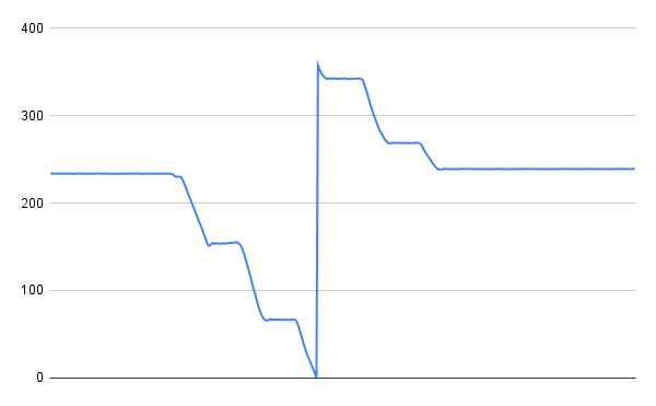
The SPI data was super noisy, which went away with a tweak (changing 8 bit to 16 bit SPI mode). I think something funky was going on between the two 8 bit halves, which is now gone. I also set the clock the DIV_16, which provides 10.64Mhz, vrs 128, which was 1.33Mhz.
Update 2:
The sensor now is wrapped in a SimpleFOC Sensor class. Something might still be a bit fragile about the SPI code. Calling the angle read back to back seems to crash the CPU.
The project repo is now on github here:
Hey @Magneon,
thanks a lot for your most valuable input! I implemented it as well, but as you were sugesting, using SPI3 on PB3/4, which is definitely much easier than using the pins you are using. I also managed to use USART1 now for debugging purposes. The hardest part was finding out how to modify the software and I haven’t found a really nice way yet, but ok, it works. As far as SPI goes, I attached an AS5147 to it, used your code, enabled SPI3 on the alternate pins in variant_B_G431B_ESC1.h and I recieve “something”, which changes as I turn the motor shaft. The problem is that the position jumps back a lot when I turn the shaft (like a reset every few rad). Do you (or anybody) else have any ideas, what could be wrong? I reduced the baudrate already, but it did not help either. Also, is there documentation on using the sensor in SSI mode somewhere available? I could not find any.
For all others that might be interested, here the changes I implemented:
A) Disconnect USART2 and connect USART1
1. Remove R23 and R24 (on the daughter board, easiest to cut them in the middle and then desolder)

B) Connect USART1 if you intend to use the serial port 1:
1. Solder thin wires to the now free pins of R23/24 (the pads closer to U3, further away from the USB port)
2. Secure the wires with some hot glue.
3. Connect the wire from R23 to the pad for hall sensor 2.
4. Connect the wire from R24 to the pad for hall sensor 1.

C) Fixes required in arduino-STM32 (only if you intend to use the serial port 1)
1. In file  …..\variants\STM32G4xx\G431C(6-8-B)U_G441CBU\variant_B_G431B_ESC1.h, change line 205ff:

#define SERIAL_UART_INSTANCE    1 //Connected to ST-Link
// Default pin used for 'Serial' instance (ex: ST-Link)
// Mandatory for Firmata
#ifndef PIN_SERIAL_RX
  #define PIN_SERIAL_RX         PB7   // PB4
#endif
#ifndef PIN_SERIAL_TX
  #define PIN_SERIAL_TX         PB6   // PB3
#endif

Save this explicitly!!!  NOTE: You will need to revert this change if you want to use USART2 again for debugging!


2. In ……\variants\STM32G4xx\G431C(6-8-B)U_G441CBU\PeripheralPins_B_G431B_ESC1.c  enable line 188 and 205.

Line 181ff:
#ifdef HAL_UART_MODULE_ENABLED
WEAK const PinMap PinMap_UART_TX[] = {
  //  {PA_2,      LPUART1, STM_PIN_DATA(STM_MODE_AF_PP, GPIO_PULLUP, GPIO_AF12_LPUART1)},
  //  {PA_2_ALT1, USART2,  STM_PIN_DATA(STM_MODE_AF_PP, GPIO_PULLUP, GPIO_AF7_USART2)},
  //  {PA_9,      USART1,  STM_PIN_DATA(STM_MODE_AF_PP, GPIO_PULLUP, GPIO_AF7_USART1)},
  //  {PA_14,     USART2,  STM_PIN_DATA(STM_MODE_AF_PP, GPIO_PULLUP, GPIO_AF7_USART2)},
  {PB_3,      USART2,  STM_PIN_DATA(STM_MODE_AF_PP, GPIO_PULLUP, GPIO_AF7_USART2)},
   {PB_6,      USART1,  STM_PIN_DATA(STM_MODE_AF_PP, GPIO_PULLUP, GPIO_AF7_USART1)},
  //  {PB_9,      USART3,  STM_PIN_DATA(STM_MODE_AF_PP, GPIO_PULLUP, GPIO_AF7_USART3)},
  //  {PB_10,     USART3,  STM_PIN_DATA(STM_MODE_AF_PP, GPIO_PULLUP, GPIO_AF7_USART3)},
  //  {PB_11,     LPUART1, STM_PIN_DATA(STM_MODE_AF_PP, GPIO_PULLUP, GPIO_AF8_LPUART1)},
  //  {PC_4,      USART1,  STM_PIN_DATA(STM_MODE_AF_PP, GPIO_PULLUP, GPIO_AF7_USART1)},
  //  {PC_10,     USART3,  STM_PIN_DATA(STM_MODE_AF_PP, GPIO_PULLUP, GPIO_AF7_USART3)},
  //  {NC,        NP,      0}
};

#ifdef HAL_UART_MODULE_ENABLED
WEAK const PinMap PinMap_UART_RX[] = {
  //  {PA_3,      LPUART1, STM_PIN_DATA(STM_MODE_AF_PP, GPIO_PULLUP, GPIO_AF12_LPUART1)},
  //  {PA_3_ALT1, USART2,  STM_PIN_DATA(STM_MODE_AF_PP, GPIO_PULLUP, GPIO_AF7_USART2)},
  //  {PA_10,     USART1,  STM_PIN_DATA(STM_MODE_AF_PP, GPIO_PULLUP, GPIO_AF7_USART1)},
  //  {PA_15,     USART2,  STM_PIN_DATA(STM_MODE_AF_PP, GPIO_PULLUP, GPIO_AF7_USART2)},
  {PB_4,          USART2,  STM_PIN_DATA(STM_MODE_AF_PP, GPIO_PULLUP, GPIO_AF7_USART2)},
  {PB_7,      USART1,  STM_PIN_DATA(STM_MODE_AF_PP, GPIO_PULLUP, GPIO_AF7_USART1)},
  //  {PB_8,      USART3,  STM_PIN_DATA(STM_MODE_AF_PP, GPIO_PULLUP, GPIO_AF7_USART3)},
  //  {PB_10,     LPUART1, STM_PIN_DATA(STM_MODE_AF_PP, GPIO_PULLUP, GPIO_AF8_LPUART1)},
  //  {PB_11,     USART3,  STM_PIN_DATA(STM_MODE_AF_PP, GPIO_PULLUP, GPIO_AF7_USART3)},
  //  {PC_11,     USART3,  STM_PIN_DATA(STM_MODE_AF_PP, GPIO_PULLUP, GPIO_AF7_USART3)},
  {NC,        NP,      0}
};
#endif

Save this explicitly!!! -> Make sure you are not using HALL_1 or HALL_2 for sensors etc. in your code anymore now!
Best regards,
Chris
Good news, I have a full fledged SPI3 running on the B-G431B-ESC1 board. It takes away the ability to perform BEMF measurement, but that’s not supported by SimpleFOC anyway. Also, you cannot attach hall sensors anymore, but at least I don’t need them if I have the SPI interface now. I tested with an AS5147 sensor on a broken board only (unfortunately I have a few of them…) so far, but I see no reason, why it should not work on a functional board too, however, that’s yet to be proven. Here is how it works:
Follow the instructions from the previous posts to use SPI3 in SSI mode. Next, you need to solder a wire connecting the BEMF sensing pin of the CPU to your sensor’s MOSI pin. I attached it to the cathode of D15. It is a very small pad to solder, but well accessible at the edge of the board. I first fixed the wire with some hot glue near the pad and then soldered it under a microscope (my hands are everything but steady). It took me some attempts, but worked.
In the code you will have to enable the pin as SPI_MOSI in …\variants\STM32G4xx\G431C(6-8-B)U_G441CBU\PeripheralPins_B_G431B_ESC1.c.In my case it looks like this (starting round line 240):
#ifdef HAL_SPI_MODULE_ENABLED
WEAK const PinMap PinMap_SPI_MOSI[] = {
  // {PA_7,      SPI1, STM_PIN_DATA(STM_MODE_AF_PP, GPIO_PULLUP, GPIO_AF5_SPI1)},
  // {PA_11,     SPI2, STM_PIN_DATA(STM_MODE_AF_PP, GPIO_PULLUP, GPIO_AF5_SPI2)},
  // {PB_5,      SPI1, STM_PIN_DATA(STM_MODE_AF_PP, GPIO_PULLUP, GPIO_AF5_SPI1)},
  // {PB_5_ALT1, SPI3, STM_PIN_DATA(STM_MODE_AF_PP, GPIO_PULLUP, GPIO_AF6_SPI3)},
  {PB_5, SPI3, STM_PIN_DATA(STM_MODE_AF_PP, GPIO_PULLUP, GPIO_AF6_SPI3)},
  // {PB_15,     SPI2, STM_PIN_DATA(STM_MODE_AF_PP, GPIO_PULLUP, GPIO_AF5_SPI2)},
  {NC,        NP,   0}
};
#endif
Note that I copied the PB_5_ALT1 line and renamed the pin to PB_5, since otherwise I ran into problems.
Now we still have the issue, that the BEMF sensing circuitry is still attached to PB5. This should not matter, if you pull all the BEMF control outputs low, before using SPI somewhere in your code:
  // BEMF outputs
  pinMode(A_BEMF1, OUTPUT);
  pinMode(PB0, OUTPUT);
  pinMode(A_BEMF3, OUTPUT);
  digitalWrite(A_BEMF1, LOW);
  digitalWrite(PB0, LOW);
  digitalWrite(A_BEMF3, LOW);
That’s it! All together well doable. Tomorow I’ll try with my last fully functioning board and a motor attached.
Cheers,
Chris
Ok, SPI is running on a functional board with motor attached as well. I tested it with the alignment_and_cogging_test example. No extensive testing so far, but looks ok.
Best,
Chris
I think this URL is no longer good, it says [DEPRECATED - Please use new package index]
I used this one to add the STM32duino (with B-G431B-ESC1 included in it):
Go to Arduino IDE → File → Preferences → Additional Board URL and add the STM32duino library: https://raw.githubusercontent.com/stm32duino/BoardManagerFiles/main/package_stmicroelectronics_index.json
Go to Arduino IDE → Tools → Boards → Boards Manager
and install STM32 MCU based boards
2 posts were split to a new topic: STM32 Hardware Timer Question
For anyone struggling, YES, TRY DISABLING THIS FLAG. It worked for me, took a little while to figure out.
Using this drone ESC right now with sensors. I don’t mind putting a big heatsink on it and a little fan, etc, but in my application I’m baffled at how little it takes for the board to overheat. I’m nowhere near 100W motor output–I’m expecting 500W out of this guy with lots of cooling applied. I’ll start a new thread.
My liquid cooling solution (very expensive liquid dielectric with high vapor point) before I decided this ESC is not very end-use friendly. It’s great to experiment however and learn new things.
Wow. You straight up submerged that guy in one of those thermal management liquids I’ve heard of. I think I saw a liter of that stuff is £50 or more, no thank you ![]() I still reckon there’s some way of getting it to do its job without melting. Otherwise, I’ll have to start looking for YET ANOTHER ESC that can do 400W, take hall sensor input, and not be sh*t. I’ve taken inspo from RC people and ordered some heatsink and fans, I’ll be reporting on progress, but that’s a little later down the line. Board gets to 45C when not even running the motor. Motor idle (and maybe drawing 0.4A??), all it did was align its sensors.
I still reckon there’s some way of getting it to do its job without melting. Otherwise, I’ll have to start looking for YET ANOTHER ESC that can do 400W, take hall sensor input, and not be sh*t. I’ve taken inspo from RC people and ordered some heatsink and fans, I’ll be reporting on progress, but that’s a little later down the line. Board gets to 45C when not even running the motor. Motor idle (and maybe drawing 0.4A??), all it did was align its sensors.
If you are interested into manufacturing your own boards, you may look into my open driver projects.
I do not offer any support or help and you are on your own, so be careful.
Cheers,
Valentine
This is so. Cool. I think I need to level up a bit more before I get this hands-on, but thanks for sharing. I only just ordered in my first assembled pcb last month–it turned out well.
Krakatoa looks fierce ![]() This may end up being what I go for in a later build. Have you fabricated any of these? What’s the whole price like compared to, say, ordering a VESC SIX($150-$250)?
This may end up being what I go for in a later build. Have you fabricated any of these? What’s the whole price like compared to, say, ordering a VESC SIX($150-$250)?
On the subject of the VESC SIX EDU, I’ve tried it, and it’s great–I especially like the software–but I don’t understand how the software needs 512Kb of Flash memory on a board to run. I also don’t understand how I don’t see any big mosfets on the boards!?
Got off topic, whoops.
The above has gone a bit out of date. Here is the beginning of an updated guide to use the B-G431-ESC with an AS5600 magnetic sensor over I2C with serial communication using an FTDI type TTL to USB serial converter. (the AS5600 is not really the best sensor as it only has a 1kHz update rate over I2C, but unfortunately it’s the one we have fallen into using, and which is widely available)
I used 12 volts as the power supply voltage. I set the other voltages quite low as my motor is a gimbal motor that has lots of torque. It had 12 ohm phase resistance, and still the board gets warm with it. You could set the supply voltage even lower or something, it may be a challenge to get it low enough to be safe with a motor that has a lower phase resistance:
Install arduino IDE
Install simpleFOC library. You may need the SimpleFOC drivers library later, but I didn’t
Update the board manager in arduino. File → preferences → additional boards manager field needs to have the following url (the above one is out of date): https://github.com/stm32duino/BoardManagerFiles/raw/main/package_stmicroelectronics_index.json
Install the STM32 arduino add-on library using the library manager in arduino.
Install the STM32cube. This is what accepts the compiled binary from the arduino IDE and gets it into the memory of the MCU.
Install the USB drivers for your USB to ttl serial adapter. The ESC is 5 volt tolerant but you might as well use 3.3 volts if you can. I recommend buying the kind of converter that has jumpers that allow you to select which voltage the adapter uses.
Now select the settings for the board as mentioned above, under the tools menu in Arduino. As a backup, the main settings are: board: “Discovery”, Board part number:“B-G431B-ESC1”, U(S)ART support: "enabled (generic “serial”), Usb support: none USB speed: low/full, Optimize: smallest -Os default, C runtime library: newlib nano, Upload method: STM32CubeProgrammer (SWD) Port: You have to figure this one out, it may detect automatically.
That upload method one is particularly important.
6.5: At this point I recommend trying the blink sketch so you know things are working BEFORE you solder. Otherwise if something goes wrong with soldering you won’t know if you broke the board of if it’s something else. Here is the blink sketch that works:
/*
  Blink
  Turns on an LED on for one second, then off for one second, repeatedly.

  This example code is in the public domain.
 */

// Pin 13 has an LED connected on most Arduino boards.
// Pin 11 has the LED on Teensy 2.0
// Pin 6  has the LED on Teensy++ 2.0
// Pin 13 has the LED on Teensy 3.0
// give it a name:
int led = 13;

// the setup routine runs once when you press reset:
void setup() {
  // initialize the digital pin as an output.
  pinMode(LED_BUILTIN, OUTPUT);
}

// the loop routine runs over and over again forever:
void loop() {
  digitalWrite(LED_BUILTIN, HIGH);   // turn the LED on (HIGH is the voltage level)
  delay(100);               // wait for a second
  digitalWrite(LED_BUILTIN, LOW);    // turn the LED off by making the voltage LOW
  delay(100);               // wait for a second
}
Solder the wires on. Use a fine tipped soldering iron and I recommend carefully cutting the wires exactly as shown in the pic, make that conductive section very short. Then tin the wires, i.e. add a small amount of solder to them. Next, with the wire in one hand and soldering iron in the other, you can hold the wire in place and melt the solder on both the pad and the wire. This prevents you from needing to hold 3 things at once. You may need to use solder flux if the wires are not pre-tinned.
I connected the wires using 2.54 mm screw terminals soldered back to back to make a sort of wire-to wire connector. You could also solder on Dupont connetors and use a solderless breadboard. If this is a development board, why do they make connecting to it so hard??
Connect the serial first. Now you can test the serial with this code. I recommend using Putty or something, not the arduino serial monitor, because Arduino keeps mixing up the com ports if you do that. Notice the baud rate is 38400 .:
#include <SimpleFOC.h>

void setup() {

  Serial.begin(38400);
  Serial.println("serial test");

 Serial.println("got this far");

  _delay(1000);
}


void loop() {
for (int i = 0;  i<2000; i++){

  }
  Serial.println("TEST serial");
 delay(100);
}
#include <SimpleFOC.h>
#include <Wire.h>

MagneticSensorI2C sensor = MagneticSensorI2C(AS5600_I2C);
// BLDC motor & driver instance
BLDCMotor motor = BLDCMotor(7);//this is common for small gimbal motors, yours may be different
BLDCDriver6PWM driver = BLDCDriver6PWM(PA8, PA7, PB3, PB0, PB6, PB1);

//float target_voltage = 3.5;
void setup() {
//Wire.setSDA(PB7);
//Wire.setSCL(PB8);
//Wire.begin();

  Serial.begin(38400);
  delay(500);
  Serial.println("serial test");
  // initialise magnetic sensor hardware
  delay(500);
  sensor.init();
  // link the motor to the sensor
  motor.linkSensor(&sensor);

  // driver config
  // power supply voltage [V]
  driver.voltage_power_supply = 24;
  driver.init();
  // link driver
  motor.linkDriver(&driver);
  motor.voltage_sensor_align = 3;
  motor.foc_modulation = FOCModulationType::SpaceVectorPWM;
  // set control loop type to be used

    motor.controller = MotionControlType::torque;
  motor.P_angle.P = 200;
  // default voltage_power_supply
  motor.voltage_limit = 6;

  // velocity low pass filtering time constant
  //motor.LPF_velocity.Tf = 0.01;


  // comment out if not needed
  motor.useMonitoring(Serial);

  // initialise motor
  motor.init();
  // align encoder and start FOC
  motor.initFOC();

  // set the inital target value
  motor.target = 3;

 Serial.println("got this far");

  _delay(1000);
}


void loop() {
for (int i = 0;  i<2000; i++){
  motor.loopFOC();

  // iterative function setting the outter loop target
  // velocity, position or voltage
  // if tatget not set in parameter uses motor.target variable
  motor.move(target_voltage);
  }
  Serial.println(sensor.getAngle());
  Serial.println("TEST serial");
  sensor.update();
}
10.open loop test. This includes the configuration for the pins etc. You may need to adjust the voltage. Don’t set it too high or you may burn out something. I used a CCCV power supply and set the current to 650 mA max to prevent disasters.
#include <SimpleFOC.h>

// NUMBER OF POLE PAIRS, NOT POLES
BLDCMotor motor = BLDCMotor(7);
// MUST USE 6PWM FOR B-G431 DRIVER
BLDCDriver6PWM driver = BLDCDriver6PWM(A_PHASE_UH, A_PHASE_UL, A_PHASE_VH, A_PHASE_VL, A_PHASE_WH, A_PHASE_WL);

void setup() {

  // driver config
  // power supply voltage [V]
  driver.voltage_power_supply = 12;
  driver.init();

  // link the motor and the driver
  motor.linkDriver(&driver);

  // limiting motor movements
  motor.voltage_limit = 3;   // [V]
  motor.velocity_limit = 3; // [rad/s]

  // open loop control config
  motor.controller = MotionControlType::velocity_openloop;

  // init motor hardware
  motor.init();

}

void loop() {
  motor.move(2);
}
/**
 * Utility arduino sketch which finds pole pair number of the motor
 *
 * To run it just set the correct pin numbers for the BLDC driver and sensor CPR value and chip select pin.
 *
 * The program will rotate your motor a specific amount and check how much it moved, and by doing a simple calculation calculate your pole pair number.
 * The pole pair number will be outputted to the serial terminal.
 *
 * If the pole pair number is well estimated your motor will start to spin in voltage mode with 2V target.
 *
 * If the code calculates negative pole pair number please invert your motor connector.
 *
 * Try running this code several times to avoid statistical errors.
 * > But in general if your motor spins, you have a good pole pairs number.
 */
#include <SimpleFOC.h>

// BLDC motor instance
// its important to put pole pairs number as 1!!!
BLDCMotor motor = BLDCMotor(1);
BLDCDriver6PWM driver = BLDCDriver6PWM(A_PHASE_UH, A_PHASE_UL, A_PHASE_VH, A_PHASE_VL, A_PHASE_WH, A_PHASE_WL);
// Stepper motor instance
// its important to put pole pairs number as 1!!!
//StepperMotor motor = StepperMotor(1);
//StepperDriver4PWM driver = StepperDriver4PWM(9, 5, 10, 6,  8);

// magnetic sensor instance - SPI
//MagneticSensorSPI sensor = MagneticSensorSPI(10, 14, 0x3FFF);
// magnetic sensor instance - I2C
MagneticSensorI2C sensor = MagneticSensorI2C(0x36, 12, 0X0C, 4);
// magnetic sensor instance - analog output
// MagneticSensorAnalog sensor = MagneticSensorAnalog(A1, 14, 1020);

void setup() {

  // initialise magnetic sensor hardware
  sensor.init();
  // link the motor to the sensor
  motor.linkSensor(&sensor);

  // power supply voltage
  // default 12V
  driver.voltage_power_supply = 12;
  driver.init();
  motor.linkDriver(&driver);

  // initialize motor hardware
  motor.init();

  // monitoring port
  Serial.begin(38400);

  // pole pairs calculation routine
  Serial.println("Pole pairs (PP) estimator");
  Serial.println("-\n");

  float pp_search_voltage = 2 ; // maximum power_supply_voltage/2
  float pp_search_angle = 6*_PI; // search electrical angle to turn

  // move motor to the electrical angle 0
  motor.controller = MotionControlType::angle_openloop;
  motor.voltage_limit=pp_search_voltage;
  motor.move(0);
  _delay(1000);
  // read the sensor angle
  sensor.update();
  float angle_begin = sensor.getAngle();
  _delay(50);

  // move the motor slowly to the electrical angle pp_search_angle
  float motor_angle = 0;
  while(motor_angle <= pp_search_angle){
    motor_angle += 0.01f;
    sensor.update(); // keep track of the overflow
    motor.move(motor_angle);
    _delay(1);
  }
  _delay(1000);
  // read the sensor value for 180
  sensor.update();
  float angle_end = sensor.getAngle();
  _delay(50);
  // turn off the motor
  motor.move(0);
  _delay(1000);

  // calculate the pole pair number
  int pp = round((pp_search_angle)/(angle_end-angle_begin));

  Serial.print(F("Estimated PP : "));
  Serial.println(pp);
  Serial.println(F("PP = Electrical angle / Encoder angle "));
  Serial.print(pp_search_angle*180/_PI);
  Serial.print(F("/"));
  Serial.print((angle_end-angle_begin)*180/_PI);
  Serial.print(F(" = "));
  Serial.println((pp_search_angle)/(angle_end-angle_begin));
  Serial.println();


  // a bit of monitoring the result
  if(pp <= 0 ){
    Serial.println(F("PP number cannot be negative"));
    Serial.println(F(" - Try changing the search_voltage value or motor/sensor configuration."));
    return;
  }else if(pp > 30){
    Serial.println(F("PP number very high, possible error."));
  }else{
    Serial.println(F("If PP is estimated well your motor should turn now!"));
    Serial.println(F(" - If it is not moving try to relaunch the program!"));
    Serial.println(F(" - You can also try to adjust the target voltage using serial terminal!"));
  }


  // set motion control loop to be used
  motor.controller = MotionControlType::torque;
  // set the pole pair number to the motor
  motor.pole_pairs = pp;
  //align sensor and start FOC
  motor.initFOC();
  _delay(1000);

  Serial.println(F("\n Motor ready."));
  Serial.println(F("Set the target voltage using serial terminal:"));
}

// uq voltage
float target_voltage = 2;

void loop() {

  // main FOC algorithm function
  // the faster you run this function the better
  // Arduino UNO loop  ~1kHz
  // Bluepill loop ~10kHz
  motor.loopFOC();

  // Motion control function
  // velocity, position or voltage (defined in motor.controller)
  // this function can be run at much lower frequency than loopFOC() function
  // You can also use motor.move() and set the motor.target in the code
  motor.move(target_voltage);

  // communicate with the user
  serialReceiveUserCommand();
}


// utility function enabling serial communication with the user to set the target values
// this function can be implemented in serialEvent function as well
void serialReceiveUserCommand() {

  // a string to hold incoming data
  static String received_chars;

  while (Serial.available()) {
    // get the new byte:
    char inChar = (char)Serial.read();
    // add it to the string buffer:
    received_chars += inChar;
    // end of user input
    if (inChar == '\n') {

      // change the motor target
      target_voltage = received_chars.toFloat();
      Serial.print("Target voltage: ");
      Serial.println(target_voltage);

      // reset the command buffer
      received_chars = "";
    }
  }
}
It’s not smart enough to adjust for a motor connected backward, if it gives the negative error, just swap any two of the motor wires.
/**
 * Comprehensive BLDC motor control example using magnetic sensor
 *
 * Using serial terminal user can send motor commands and configure the motor and FOC in real-time:
 * - configure PID controller constants
 * - change motion control loops
 * - monitor motor variabels
 * - set target values
 * - check all the configuration values
 *
 * See more info in docs.simplefoc.com/commander_interface
 */
#include <SimpleFOC.h>

// magnetic sensor instance - SPI
MagneticSensorI2C sensor = MagneticSensorI2C(0x36, 12, 0X0C, 4);
// magnetic sensor instance - MagneticSensorI2C
//MagneticSensorI2C sensor = MagneticSensorI2C(AS5600_I2C);
// magnetic sensor instance - analog output
// MagneticSensorAnalog sensor = MagneticSensorAnalog(A1, 14, 1020);


// BLDC motor & driver instance
BLDCMotor motor = BLDCMotor(7);
BLDCDriver6PWM driver = BLDCDriver6PWM(A_PHASE_UH, A_PHASE_UL, A_PHASE_VH, A_PHASE_VL, A_PHASE_WH, A_PHASE_WL);
// Stepper motor & driver instance
//StepperMotor motor = StepperMotor(50);
//StepperDriver4PWM driver = StepperDriver4PWM(9, 5, 10, 6,  8);

// commander interface
Commander command = Commander(Serial);
void onMotor(char* cmd){ command.motor(&motor, cmd); }

void setup() {

  // initialise magnetic sensor hardware
  sensor.init();
  // link the motor to the sensor
  motor.linkSensor(&sensor);

  // driver config
  // power supply voltage [V]
  driver.voltage_power_supply = 12;
  driver.init();
  // link driver
  motor.linkDriver(&driver);

  // choose FOC modulation
  motor.foc_modulation = FOCModulationType::SpaceVectorPWM;

  // set control loop type to be used
  motor.controller = MotionControlType::torque;

  // contoller configuration based on the control type
  motor.PID_velocity.P = 0.2f;
  motor.PID_velocity.I = 20;
  motor.PID_velocity.D = 0;
  // default voltage_power_supply
  motor.voltage_limit = 4;

  // velocity low pass filtering time constant
  motor.LPF_velocity.Tf = 0.01f;

  // angle loop controller
  motor.P_angle.P = 20;
  // angle loop velocity limit
  motor.velocity_limit = 50;

  // use monitoring with serial for motor init
  // monitoring port
  Serial.begin(38400);
  // comment out if not needed
  motor.useMonitoring(Serial);

  // initialise motor
  motor.init();
  // align encoder and start FOC
  motor.initFOC();

  // set the inital target value
  motor.target = 2;

  // define the motor id
  command.add('A', onMotor, "motor");

  // Run user commands to configure and the motor (find the full command list in docs.simplefoc.com)
  Serial.println(F("Motor commands sketch | Initial motion control > torque/voltage : target 2V."));

  _delay(1000);
}


void loop() {
  // iterative setting FOC phase voltage
  motor.loopFOC();

  // iterative function setting the outter loop target
  // velocity, position or voltage
  // if tatget not set in parameter uses motor.target variable
  motor.move();

  // user communication
  command.run();
}
At this point, things broke down for me. The exact same problem was seen with different sensors, and with 3 different boards, the lepton V2, the Bluepill with a 6 pin power stage, and with this ESC board. If I set the pole pair numbers to 8 and set the voltage high enough, it spins sometimes and not others, with a sort of speed distortion/shaking once per rotation. I manually counted the pole pairs, it is definitely 7. When I set it to 7 it sits there and shakes. I have not been able to solve this.
Since there is doubt that SimpleFOC can provide the RPM I need (above comments indicate 60 rad/s even with this high speed MCU) I am trying some other things first, but may be forced to return to SimpleFOC later.
Have you had any luck spinning the motor open-loop with the polepair calibration example? when I was initially having problems with one set of motors I edited it to make the calibration angle larger and that got me a better result. I also encountered similar results to the shaking you’re describing when I only had two pole pairs of my motor fully connected instead of three.
Was that speed limited by the AS5600/I2C or something else? The AS5047P works for me on this board via A/B/Z, which I’ve read is much faster than I2C.
On a small 320kV 2208 motor with this board and the AS5600 I’ve been able to achieve >75 rad/s, just limited by my power supply voltage.
I gave up on trying to do everything on one microcontroller, the g431 board now only does open loop waveform generation. I tell it the rads/second over uart, it does some adjustment of the voltage to compensate for back emf and normal fan loading. Then it tells the pico the electrical angle, and the pico reads the sensor and regulates the phase angle i.e. sensor vs electrical angle.
Basically, the g431 board does all the stuff that needs to be done quickly, and the pico does the stuff that can be done slowly.
Might not seem to make sense, but it has proven to be a much less capital intensive road to developing a quiet system. The problem with using one MCU for everything is that any tiny thing can cause noise and it’s ten times as much work to nail everything.
I tried several other things such as the firmware that ST microelectronics provides as an example FOC sensorless driver, but they did a crummy job and nothing works, and you can’t get in there to change and repair anything, so that was a dead end.
Out of curiosity @Anthony_Douglas ,how fast does your fan need to spin, and how quiet does it need to be?