AS5600 + GBM2804H-100T, not working in closed loop, vibrating or idling

Hello everyone,

I am trying to build a very basic setup with an ESP32 + AS5600 + GBM2804H-100T + SimpleFOC board, working in any closed loop mode (torque, velocity, angle). However I am facing an issue that got me completely lost.

I am able to run the project in open loop modes (angle and velocity) without any problem (small video x.com).

But, when I try to set any closed loop modes it will fail with either vibrating or idling. I can rotate the motor with my hands, and while doing so, from time to time it jumps to another angle.

I have checked:

  • The magnet of the AS5600: I can read the position perfectly, and for the whole rotation.
  • I have tried changing the poles / coil resistance parameters.
  • Played with PID tunning for angle and velocity
  • Downsampling the movements/measurements

One thing to note is that the PP almost always fails, and the example to get the polepairs almost always return negative values, and when it returns a positive value dont event turn after gettting it.

I can add a connection diagram but, since the movement and sensor is working I understand the AS5600 and the motor are working nice.

Anyone has any idea what can I test next? What can I change?

#define ESP_H
#include <Arduino.h>
#include "SimpleFOC.h"

MagneticSensorI2C sensor = MagneticSensorI2C(0x36, 12, 0x0E, 4);
BLDCMotor motor = BLDCMotor(7);
BLDCDriver3PWM driver = BLDCDriver3PWM(18, 4, 5,19);

Commander command = Commander(Serial);
void doMotor(char* cmd) { command.motor(&motor, cmd); }

void setup() {
  
  Serial.begin(115200);

  sensor.init();
  Serial.println("AS5600 ready");
  
  driver.pwm_frequency = 20000;
  // power supply voltage [V]
  driver.voltage_power_supply = 12;
  // Max DC voltage allowed - default voltage_power_supply
  driver.voltage_limit = 4;
  // driver init
  driver.init();
  Serial.println("Driver ready");

  motor.linkSensor(&sensor);
  motor.linkDriver(&driver);
  motor.useMonitoring(Serial);
  motor.controller = MotionControlType::torque;
  motor.init();

  motor.initFOC();

  command.add('M', doMotor, "motor");
}


void loop() {
  motor.loopFOC();

  motor.move();
  motor.monitor();
  
  command.run();
}

Hello,
You should test with this example: “find_sensor_offset_and_direction”
https://github.com/simplefoc/Arduino-FOC/blob/master/examples/utils/calibration/find_sensor_offset_and_direction/find_sensor_offset_and_direction.ino

I have just test it several times, and it gives me different values ranging from 0.7 to amost 4.0.

Sensor zero offset is:
2.6415
Sensor natural direction is:
Direction::CCW
To use these values provide them to the: motor.initFOC(offset, direction)
If motor is not moving the alignment procedure was not successfull!!

It says that the motor should be moving after the aligment, but it is not :frowning: …

Hummmm …
Try changing the i2c speed …

#include <Wire.h>
#define SDA 21
#define SCL 22

void setup() {
...
  // initialise magnetic sensor hardware
  Wire.begin(SDA, SCL);
  Wire.setClock(3400000); // Try calling Wire.setClock(400000) or 1000000 or 3400000 to speed up the i2c bus.
...
  }

And add motor direction

motor.sensor_direction = Direction::CCW; // CW or CCW

It sounds like a sensor problem. Print out sensor.getAngle() and turn the motor by hand and see if the angle changes as it should.

1 Like

It seems a sensor problem yes, when I tried moving the motor, was without powering the 12V.

Now I have tried moving the motor with the power supply on, and the result are noisier.

Any idea how can I filter this?

@multisystem , I tried your proposal but still same result. Now I am more inclined to think the problem is the sensor. I need to improve the reading.

what is the pullup resistance of your i2c sensor?

1 Like

You have to get the layers working in order, the parts that come after the pole pair check will never work if the PP check doesn’t work. I had a problem a lot like this with the same sensor and what was happening is that the direction pin needed to be help high or low. When the motor was unpowered everything worked fine, but when powered the readings became erratic. It sounds like you have a similar issue with noise or something.

I would get into the code and put some print statement that print out the angle while the pole pair check is proceeding.

In general, go upstream and print things out to check the variables are what you think they are. Just modify the source code on your computer, you an use source.simplefoc.com to browse around and see the structure of the code but the search feature doesn’t seem to work right unfortunately. Sometimes I have to use the search feature of file explorer to find stuff in the source code on my hard drive.

You can initialize the serial port in your code, I recommend 1 million baud to reduce complications, and then put Serial.print() statements almost anywhere I think, in the code base.

Yeah people forget the pullups sometimes, but most as5600 boards have pullups on them, which board are you using?

I had forgotten, but I also had this problem of “dir” in the air, it is imperative that it is high or low.

1 Like

Thank you for your help!

About the I2C signal and DIR pin, I have 4.7k pullups, and I have tied the DIR and GP0 to GND/VCC.

I have tried adding a print statement during calibration, more precisely in BLDCMotor::alignSensor(), I now print the angle read during cw and ccw movement. And I find something interesting.

    // find natural direction
    // move one electrical revolution forward
    for (int i = 0; i <=500; i++ ) {
      float angle = _3PI_2 + _2PI * i / 500.0f;
      setPhaseVoltage(voltage_sensor_align, 0,  angle);
	    sensor->update();
      SIMPLEFOC_DEBUG("TEST: angle:", sensor->getAngle());
      _delay(2);
    }

I modified the code so, when the calibration is done and the result is printed out, the ESP32 restarts itself and redoit again. This way I can just let it work and save the log in a file and then analyze it. I have run two tests:

  • The first one, I just leave the ESP and the motor doing their calibration.
  • During the second test, I just move the motor randomly so every calibration starts in a different angle.

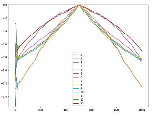
And here are the results for test one, it is amazing how similar they are, I have check the log and yes, there is no problem in the script, the data are as similar as is shown in the graph. Also notice some startup movement in the bottom left side. However, with this results, I would say that the sensor is working pretty nice.

Lets go with the second test, where I change the starting position of the motor before running the calibration. And here are the results…

Now we can see that there are huge movement spike during startup which may affect the results. Also, here the movement is not consistent between runs. I will try to run this test with different magnet configuration, or different magnet holder to check if I can improve this. Nevertheless, it is impossible to calculate the PP with this data, is so random.

I will keep investigating, I just leave this here if someone is interested in this problems.

Thank you all

1 Like

Thank you for sharing this, this is a nice test!

It would be interesting to hear the results of your investigation!

Interesting. The initial spike makes sense because the coils are being energized the same every time, so it should jump from wherever it is to the common beginning electrical angle. But I would expect them all to match after that. Perhaps the magnet and/or sensor is mounted slightly off center? It does look like there are 7 unique curves in the second plot, likely corresponding to the 7 unique electrical revolutions that you may land on when randomizing the start position.

What is the scale on the left? Is it in radians?

Because you would expect 7 different distinct zero positions on a 7 pole pair motor. And in absolute angle terms they would be offset from each other by 2PI/7 rad, or about 0.9rad.

That’s not really what we see in that picture…

Thank you guys for your interest.

On those test, I had 2 magnets one on top of another to increase the magnetic field, and actually the position sensing improved. And actually I think that what we see in the 2nd graph is that the top magnet cannot keep the first kick and has the oscillation we see.

About the test procedure: what you see in the graph is the calibration phase. I just recorded the data and then normalize them so the maximum is 0 for all of them so way we can compare them.

Sadly a stronger magnet will take round 1-2 months to arrive :frowning: so I will have to look for other ideas to improve the sensing. I will keep this post update :slight_smile:

Hi,
just wondering how you stacked the two magnets? In my imagination you let them snap together the way they want… N to S and S to N.
But IMHO that wouldn’t increase the magnet field.

When I built my own BLDC motors, I had to use force to place two magnets side by side, if I wanted a wider magnet with same polarity.

I’m also very doubtful 2 magnets is a good idea. The fields won’t be aligned unless you epoxy them exactly in place.
And unless they are glued together, the top one is free to vibrate/move. So you won’t get accurate readings.

I think you will get better results with just a single magnet, but moved closer to the sensor and further away from the motor. Are you using the built-in magnet on the iPower motor? Is it the version that comes with a sensor? In my experience this works well out of the box? Or is it a different motor?

Oh, you both are right! I just leave them stack using magnetic force, so the field would not add… However it was working better. I will try to change the magnet holder.

I am using this motor, I would say the small inner piece is not a magnet, right? I am using a 3d printed holder for a disk magnet that fits in the hollow axis.

I have already ordered stronger magnets, but until they arrive, I will try to design of the magnet holder.

Yes, this is the model without the built-in magnet.

It should run fine with a printed magnet holder, and 6x3mm or 6x2.5mm diametrical magnet of good quality. I have used this motor myself, and it easy to use.
It’s important that the magnet and the magnet-holder sits very tightly to be 100% sure it cannot move. If the magnet is loose, it won’t work well at all.
When testing, make sure the motor does not get too hot or it will melt/deform the magnet-holder.

How big is your magnet?

Can you show us a pic of your magnet holder? You can’t use a disk magnet sideways if that you are thinking.