Are 3 linear halls in 60° possible with linear halls library?

Hi,
the title almost describes it all.
I have 8 pole BLDC motors with an external 8_magnets rotor and 3 digi halls. Easiest hack would be to replace them with linear halls.
I could also rip the rotor off and replace it with a mag sensor like AS5048, but then the cover wouldn’t fit anymore.

Third option came up, while writing this: make a new hall pcb with 90° or any other angle you’d think will fit a 4PP motor.

25 Answers

25

The “weak” ReadLinearHalls function lets you make custom ADC setups without editing LinearHall itself. Set up ADCinput in your main setup() function and make a ReadLinearHalls that returns the results from it.

It looks like it should work. Try commenting out the calls to pinMode in both versions of LinearHall::init. I had them commented out before to ensure that they wouldn’t interfere with custom ADC configuration, but uncommented since it seemed to work either way on STM32, but the other day I discovered that certain ADC channels don’t work after calling pinMode so I’ll be commenting them back out again before the next pull request. Maybe it messes up RP’s ADCInput as well.

lol, you keep finding everything I’ve written code for but haven’t tested yet. Here you go: Arduino-FOC-drivers/src/encoders/linearhall at dev · dekutree64/Arduino-FOC-drivers · GitHub

It only uses two of them, but applies a correction factor for 120° spacing. I also added a correction factor for difference in amplitude of each sensor’s sine wave for improved accuracy.

Before you desolder the digitals, try holding a linear about the same distance from the magnets and make sure the value doesn’t saturate. If it does, you could probably make it work by soldering them not quite flush with the board so you can bend them away a little bit, which will reduce the sensed field strength due to angle and distance.

How do I set 120° angle?

class LinearHall: public Sensor{
  public:
    // Note: With sensor_spacing_120 you may need to swap hallA and hallB (one way is effectively -240 degrees apart and won't work).
    LinearHall(int hallA, int hallB, int pp, bool sensor_spacing_120 = false);

Do I have to modify LinearHall.h to true or can I set sensor.sensor_spacing_120 = true before I init the sensor?

That's an argument to the constructor which defaults to false. You can either pass in true when creating it or set it before calling init, whichever you prefer.

Made a sketch to see if I could fit the linear halls in 90° next to the 120° regular halls.
But I might as well CNC it from perfboard to be able to switch back to the original PCB.

My 49E halls arrived yesterday. Today I wanted to install Hantek USB-Oscilloscope driver on a Win11 PC, but no chance… I tried everything AI suggested as solution, but gave up after several hours.

Is there a chance to use rp2350 AD channels with webcontrol over simpleFOC?

Just print sensor.lastA or B, open serial plotter in Arduino IDE, and rotate the motor by hand (preferably with a pulley on the shaft for better grip).

In the meantime I hotglued a sensor next to the regular hall and read between 1.15V and 2.15V with a multimeter.
Also tested with a diametral magnet and min/max with direct contact was 0.8/2.5V.

Is 1V peak2peak enough or should I try to get closer?

Will try your solution tomorrow.

That should be fine.

Replaced two halls today and tried to make it run in 120° mode.
The motor initializes, but other than that only vibrates.

  • I tried to switch the hall signals => same or even worse jitter (sensor direction switches from CCW to CW)
  • also switched two driver pins, because of the CW sensor direction => Iq locks at current_limit, but no movement

The whole init procedure is quite noisy, maybe the AD converter of rp2350 isn’t that good?


LinearHall centerA: 565, centerB: 630	//	is quite noisy +/-25
, amplitude_ratio: 0.72					//	ratio is all over the place, between 0.6 and 1.2
LinearHall centerA: 565, centerB: 630
MOT:Align sensor.
MOT:sensor dir: CCW
MOT:PP check: OK!
Skip dir calib.
MOT:Zero elec. angle: 5.13				//	differs between 5.1 and 6.2	
ERR-MOT:No current sense.				//	TorqueControl is estimated_current
MOT:Ready.
Motor ready.
Set the target velocity using serial terminal:
M0.0000	-23.4804M
M0.0000	19.4706M
M0.0000	19.1144M

I just got my 120° test set up and it’s working fine. My readings are about 0.6V peak-to-peak, so I doubt the magnet distance is your issue.

Did you try the lastA and lastB plotting? That will give you a much better idea what’s going on. See the noise level when holding still, and if the sine wave amplitude varies with each magnet pair.

LinearHall is pretty robust, so there must be something majorly wrong. When I was first working with it, my 7pp test motor ran fine despite a fair amount of amplitude variation with each electrical revolution and only ~0.4V peak-to-peak.

I’ve heard RP2040’s ADC has a hardware bug that makes the lower bits unreliable, but since analogRead’s 10-bit return value is already discarding the low 2 bits, its effect should be minimal. And I think it was fixed on RP2350 anyway.

Yes, I tried but it didn’t work.
Why do I also have to enable motor.monitoring to see anything on the plotter? I expected motor.loopFOC would refresh lastA?
But then the data floods the com port. I checked with the serial monitor and there are hundred of lastA, lastB before I see a line with motor target and velocity.
Default monitor_downsampling is 100, so that explains it.

Here is my main loop and the output:


void loop() {
  
  motor.loopFOC();

  motor.move(motor.target);

  motor.monitor();
  Serial.print("LastA");
  Serial.print(halls.lastA);
  Serial.print(",");
  Serial.print("LastB");
  Serial.println(halls.lastB);
  // command.run();
}

// Output over serial monitor
LastA331,LastB578
LastA332,LastB578
LastA331,LastB579
LastA428,LastB579
LastA332,LastB972
0.0000	62.5930
LastA332,LastB580
LastA332,LastB819
LastA340,LastB582
LastA332,LastB583
LastA332,LastB806
LastA332,LastB584

Aha, I figured out that the plotter is really sensitive to data formatting errors: I forgot the : in Serial.print("LastA"); And don't use a space between the variable name and the : either

Just figured out why you have to call useMonitoring. I changed LinearHall::init to use motor->monitor_port instead of calling Serial.print directly after I'd seen some other class to it that way, but if monitor_port is null it crashes. I think I'll just change it back to direct print so you don't have to enable monitoring to get the calibration printout.

In your code example you are using sensor.init(&motor); Serial.print("LinearHall centerA: "); Serial.print(sensor.centerA); which might confuse the IDE plotter interface when opened before setup is done. I replaced it with Serial.print("LinearHall centerA = "); Just to be on the seafe side

You shouldn’t have to call motor.monitor();. If you’re not calling Serial.begin(115200); at startup, do it. But I don’t think the monitor functions would work without it either.

If it’s able to keep up with the data flood, that is actually better to be able to see exactly how often you’re getting bad readings. But if it seems to be struggling, try this:

  static int32_t lastPrintTime = 0;
  int32_t t = millis();
  if (t - lastPrintTime >= 50) {
    lastPrintTime = t;
    // Print stuff here
  }

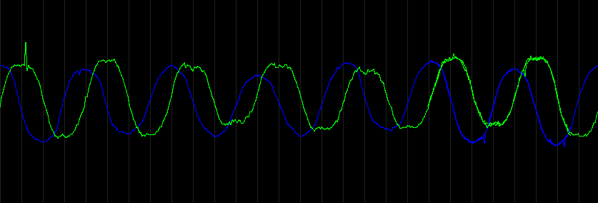
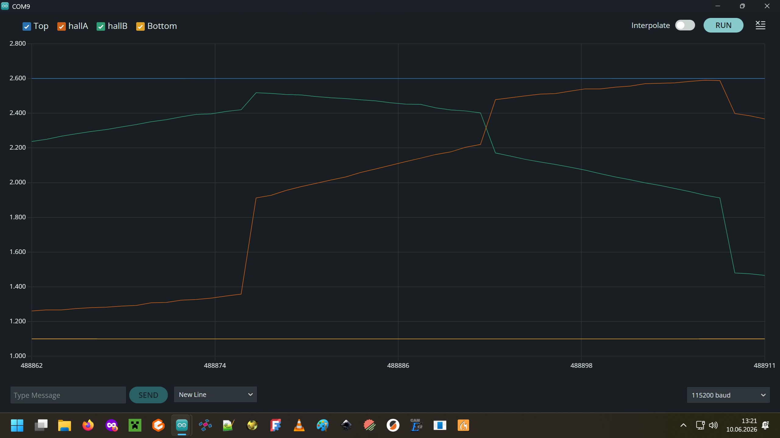
From the little data you’ve got, it looks like you’re getting big spikes rather than steady noise. See if you can find anything that changes the pattern. Fiddle with the wiring, pick up the motor and move closer or farther from potential EMI sources, try a different power source if it’s not too much trouble, different USB port and/or cable, or anything else you can think of.

You could try adding a simple spike filter:

void ReadLinearHalls(int hallA, int hallB, int *a, int *b)
{
  int threshold = 50;
  static int olderA = *a, olderB = *b, oldA = *a, oldB = *b;
  int newA = analogRead(hallA), newB = analogRead(hallB);
  *a = abs(newA-oldA) > threshold && abs(newA-olderA) > threshold ? oldA : newA;
  *b = abs(newB-oldB) > threshold && abs(newB-olderB) > threshold ? oldB : newB;
  olderA = oldA, oldA = newA, olderB = oldB, oldB = newB;
}

Technically those static variables should go in the sensor class, but as long as there’s only one instance of it this will work.

Basically it says if the new reading is more than 50 units different from the previous two, it’s probably a spike so reuse the previous reading. It won’t work if spikes are so frequent that you get two consecutively (likely, if 3 of 11 readings are bad), or if you get spike,good,spike and both spikes are within 50 units of eachother. But since the B972 and B819 spikes in your printout are more than 50 different from eachother, it would still catch both of them.

Here is the stripped down code, but I don’t get any data. Since I first flashed the analog hall program, my COM port crashes from time to time. I have to use the UF2 port for flashing, then switch back to COM. Maybe the rp2350 is toasted?

/*
 Linear Halls in 120° test
 */
#include <SimpleFOC.h>
#include <SimpleFOCDrivers.h>
#include <encoders/linearhall/LinearHall.h>

BLDCMotor motor = BLDCMotor(4, 1.1f, 167.0f); // 4 pole pairs, 1.1R phase resistance, kv=167
BLDCDriver3PWM driver = BLDCDriver3PWM(4,5,6,7);

LinearHall sensor = LinearHall(A0, A1, 4, true);

float target_velocity = 0.0f;

void setup() {

  Serial.begin(921600);
  _delay(1000);
  
  driver.voltage_power_supply = 24;
  driver.voltage_limit = 24;
  driver.init();
  
  motor.linkDriver(&driver);
  
  motor.foc_modulation = FOCModulationType::SpaceVectorPWM;
  motor.controller = MotionControlType::velocity; 
  motor.torque_controller = TorqueControlType::estimated_current;
  motor.voltage_limit = 0.58f * driver.voltage_limit; 
  motor.voltage_sensor_align = 2.0f;  
  motor.current_limit = 1.0f;
  motor.PID_velocity.limit = motor.current_limit;
  motor.PID_velocity.P = 0.0f;  //  0.08f;
  motor.PID_velocity.I = 0.0f;  //  1.0f;
  motor.LPF_velocity.Tf = 0.001f;
  
  motor.PID_velocity.output_ramp = 300;
 
  motor.init();
  // initialize sensor hardware. This moves the motor to find the min/max sensor readings and 
  // averages them to get the center values. The motor can't move until motor.init is called, and 
  // motor.initFOC can't do its calibration until the sensor is intialized, so this must be done inbetween.
  // You can then take the values printed to the serial monitor and pass them to sensor.init to 
  // avoid having to move the motor every time. In that case it doesn't matter whether sensor.init 
  // is called before or after motor.init.
  sensor.init(&motor);
  Serial.print("LinearHall centerA = ");
  Serial.print(sensor.centerA);
  Serial.print(", centerB = ");
  Serial.println(sensor.centerB);
  
  motor.linkSensor(&sensor);
  motor.initFOC();
  _delay(1000);
}

void loop() {
  
  motor.loopFOC();
  motor.move(target_velocity);

  Serial.print("LastA:");
  Serial.print(sensor.lastA);
  Serial.print(",");
  Serial.print("LastB:");
  Serial.println(sensor.lastB);  
}

Something I learned today, but you probably know already:


If you're sampling audio, sensors at high speed, or multiple channels, 
the Arduino-Pico core provides an ADCInput class that uses the ADC hardware in streaming mode 
instead of repeated analogRead() calls. 
This is intended for continuous acquisition.

Example concept:

`#include <ADCInput.h>`

`ADCInput adc(A0);` 

ADCInput is generally a much better fit than repeated analogRead() calls 
when you're running a time-critical control loop such as FOC (Field-Oriented Control), 
but the details depend on how deterministic your timing requirements are.

Why analogRead() can be problematic
analogRead() is synchronous

The CPU waits for the ADC conversion to complete before continuing. 
If you're running a FOC loop at 10–40 kHz, those blocking calls add latency and jitter.

How ADCInput helps

In the Arduino-Pico implementation, ADCInput can use the RP2350 ADC in continuous mode with buffering. 
The ADC hardware performs conversions independently, and your code reads samples from a buffer later.

Nifty, I did not know about ADCInput. I haven’t used RP2350 much, but from what I have, it seems like the best successor to Uno/Nano for general use. With a large number of ADC samples per frame, you can filter most of the spikes and drown the rest out with averaging.

I do vaguely remember having some kind of trouble with serial when I was using grblHAL on RP2350. Have you tried lower baud rate? I suppose the high rate is why it’s able to cope with the data flood, but no good if it’s unstable.

I always use 921600 baud with the webcontroller or Serial monitor, but I lowered it to 115200 with no effect. But as I wrote before, the current rp2350 is acting up. (freezing the COM port) Maybe because of the blocking analogRead()

I’m tempted to write a sample code with ADCinput vs. analogRead, but I’m not sure if I can rewrite the LinearHall code. Especially when you want to keep it HW-neutral.

I tested the ADCInput with a little code apart from simpleFOC:

#include <ADCInput.h>

ADCInput halls(A0, A1);

void setup() {
  Serial.begin(115200);
  halls.begin(20000);
}

void loop() {
  while (halls.available() >= 2) {
    int hallA = halls.read();
    int hallB = halls.read();

   Serial.print("Top:"); Serial.print(2600); Serial.print('\t');
   Serial.print("hallA:"); Serial.print(hallA); Serial.print('\t');
   Serial.print("hallB:"); Serial.print(hallB); Serial.print('\t');
   Serial.print("Bottom:"); Serial.println(1200);

  }
}

It worked really well, but I could never see a nice sine/cosine wave with the Serial plotter.
Tried different baud rates and ADC polling frequencies…
BTW: when I flashed it for the first time, I had to use UF2 port, but once it was done the COM port never froze again, so I assume there is something wrong with polling analogRead() too often.

I have an idea, why my motor blocks and hums no matter how I arrange halls and driver pins:
The halls.zero-offset_angle aligns with the magnetic disk but not with the motor magnets.
I mounted the PCB as_it_was_before, but maybe not good enough.

On second thought, that would also happen with magnetic sensors like AS5600, so I guess sFOC takes care of that. Maybe sensor calibration would help

Here is the best screenshot I could make, using a cordless drill on the motorshaft.
I hope i didn’t damage the DRV8313 driver board

The mag-field is very inconsistent. I think, a flux ring around the disk would be nice.

It’s probably fine. The lines look smooth and spike-free, I think those jumps are just where the UART gets overloaded and misses a bunch of data points. Try setting it to halls.begin(100); and turn it by hand.

I was about to say that coexisting with current sense on DRV8316 would be a problem, but apparently lowside sensing is not supported yet on the RP microcontrollers anyway. But in the long run I think we’ll need to add support in this RP2040ADCEngine class to add extra channels for LinearHall, since analogRead or ADCInput would mess up the PWM-synchronized configuration.