100Hz sample rate helped a lot. I wish we could set a polling frequency for LinearHalls, too.
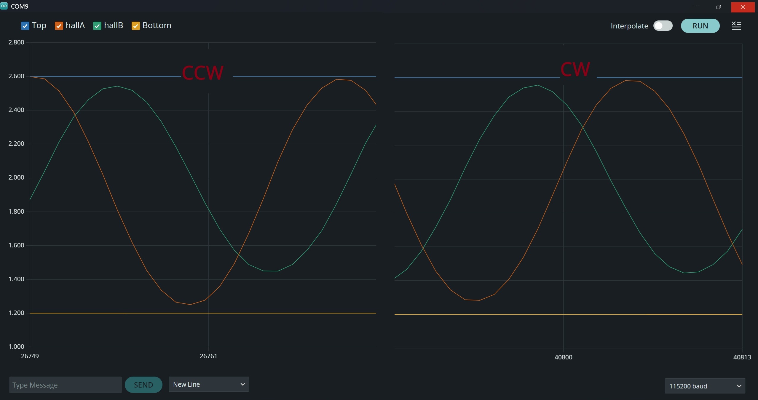
I’ve made a snapshot of CW and CCW rotation. Is this the way it should be or do I have to switch halls?
Beautiful waveforms. That should work great. I wonder what analogRead’s problem was.
There’s a 50% chance I’d be correct if I told you to switch them  I need to mess around with it until I understand which way it goes and then add an auto-calibration for it (I think negating amplitude_ratio would have the same effect as swapping the sensors). For now just try it both ways and see which one gives good angle tracking.
Did you notice it’s 12bit and no visible noise.
That waveform is with 100Hz, but the motor will spin 520rad/s * 4pp, and we want to scan the sinewave at least 8-10 times per revolution.
20kHz is my target, but ChatGPT also said the sample rate should always be faster than the FOC-loop.
I know from the rp2040 “scoppy” project that 500k Hz sample rate is possible. (they use it for an android-oscilloscope). The rp2350 can do even more.
Today I will try to rewrite the weak ReadLinearHalls function and plot the output.
I would really like to use it standalone for testing, but I have to go through all the driver/motor/sensor-inits before it works…
You can do that once the calibration values are known. There’s a second version of init that takes the centerA, centerB, and amplitude ratio so it doesn’t have to move the motor. Which from your image, should be sensor.init(1924, 1825, 0.822);
I think 500kHz is still the max sample rate on RP2350 (section 12.4 of the datasheet). Ideally I’d want to set it up to read continuously into a circular buffer of 16 samples per channel, and have ReadLinearHalls add up all the samples in the buffer to improve the resolution. That way you get the 16 most recent samples, and don’t care what order they’re in since you’re going to use all of them. But that ADCInput class is based on the I2S audio code, which is written to keep careful track of the order and avoid overrun, so for now we should use a different approach.
The documentation for ADCInput is not clear at all how it works, but if I’m understanding the code correctly from a quick read, it doesn’t make data available until a buffer is completely filled, and defaults to 16 samples per buffer, and up to 8 buffers filled before it oveflows.
I think we should reconfigure the buffer arrangement to halls.setBuffers(8, 2); so it only stores one pair of samples in each buffer for minimum latency. Set frequency to 80KHz (4 times your 20KHz FOC loop rate) so there will typically be 4 buffers (8 total samples) available each update, but sometimes could be one more or less which is ok too. And will typically have 4 spare empty buffers so it’s nowhere near overflow. We could do more than 80kHz but then this averaging method would be a bit wasteful since it chops off the lower bits, and the alternative is slightly more confusing.
void ReadLinearHalls(int hallA, int hallB, int *a, int *b) {
  int sumA = 0, sumB = 0, count = 0;
  while (halls.available() >= 2)
    sumA += halls.read(), sumB += halls.read(), count++;
  if (count) // There should always be new samples, but if not, lastA and lastB will be reused
    *a = sumA / count, *b = sumB / count;
}
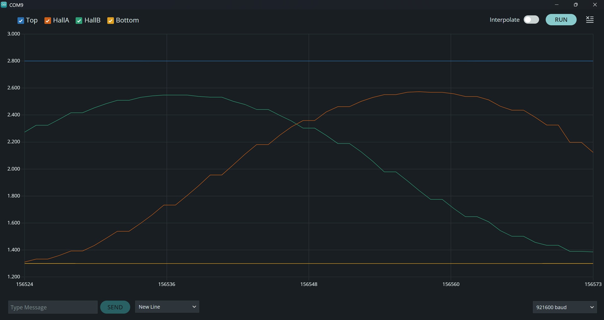
Here is, what I cobbled together. Tried different things, but the sensor doesn’t update more than once.
When I start the plotter, I see two different values. But once I move the motor shaft, both values jump to ~2750 and stay there.
#include <ADCInput.h>
#include <SimpleFOC.h>
#include <SimpleFOCDrivers.h>
#include <encoders/linearhall/LinearHall.h>

ADCInput halls(A0, A1);

LinearHall sensor = LinearHall(A0, A1, 4, true);

//overwrite ReadLinearHalls
/*
void ReadLinearHalls(int hallA, int hallB, int *a, int *b) {
  int sumA = 0, sumB = 0, count = 0;
  while (halls.available() >= 2)
    sumA += halls.read(), sumB += halls.read(), count++;
  if (count) // There should always be new samples, but if not, lastA and lastB will be reused
    *a = sumA / count, *b = sumB / count;
}
*/
void ReadLinearHalls(int hallA, int hallB, int *a, int *b) {
    while (halls.available() >= 2){
    *a = halls.read();
    *b = halls.read();
    }
  }


void setup() {
  Serial.begin(921600);
  _delay(1000);

  //halls.setBuffers(8, 2);
  halls.begin(80000);

  sensor.init(1924, 1825, 1.0);   //  0.822
}

void loop() {

   //	 How do I update the sensor
   sensor.update();
   //sensor.getSensorAngle();

  Serial.print("Top:"); Serial.print(2800); Serial.print(",");
  Serial.print("HallA:"); Serial.print(sensor.lastA); Serial.print(",");
	Serial.print("HallB:"); Serial.print(sensor.lastB); Serial.print(",");
//  Serial.print("Angle:"); Serial.print(sensor.getSensorAngle()); Serial.print(",");
  Serial.print("Bottom:"); Serial.print(1300); Serial.print(",");
  Serial.println("\r");

}
Hmmm, I modified ::readSensors to -1/sqrt(3) * a and even removed if(sensor_spacing_120), but the phaseshift doesn’t change.
float LinearHall::readSensors() {
  ReadLinearHalls(pinA, pinB, &lastA, &lastB);
  float a = lastA - centerA, b = (lastB - centerB) * amplitude_ratio;

  b = b * _2_SQRT3 - a * _1_SQRT3; // Clarke transform, as in CurrentSense::getABCurrents

  return _atan2(a, b);
It only applies the correction to the temporary variable there, so you'll need to set lastB = b for it to show on your printout.
– dekutree64After a bit more testing the standalone LH version, I took the plunge and modified the velocity sketch.
Immediately I ran into the same COM-freeze problems as before.
But with the help of @dekutree64 I had some rough estimations for centerA/B and amp-ratio, so I tried to avoid
sensor.init(&motor)
Finally the whole initialisation routine worked, but I still had no running motor…
So I borrowed some code from the init routines and wrote my own standalone LH-init.
At first I got false minA and minB values
/*	before "speedcontrol"
		maxA:2553,   maxB:2596,   minA:0,   minB:0,   centerA: 1276,   centerB: 1298,   ratio: 0.98,
	after
		maxA:2591,   minA:1256,   maxB:2552,   minB:1392,   centerA: 1923,   centerB: 1972,   ratio: 1.15
*/
I changed the way the variables where preset:
int minA = 2500, minB = 2500; //  dummy variables for centerA, centerB, amp_ratio
int maxA = 0, maxB = 0;   	  //  inverse preset
…and added if (sensor.lastA > 0 ){ to my sensor.init.
With the new found values, I could finally run the motor, although it sounds quite rough and can merely do 200rad/s (500rad/s with digital halls). But it’s a starting point.
I had to change the b=b... +a*... equation to -a*.... Now the motor runs much smoother.
I tried to figure out a way to let init do that automatically, but without currentSense it is pretty impossible.
I suggest changing bool _sensor_spacing_120 to an int and let the user define it as 60,90,120.
That way the init routine could change an internal variable to -1,0,+1 accordingly.
The phase correction function would be like:
if(sensor_spacing <> 0)   // not 90°, so it's either -1 or +1
    b = b * 2_SQRT3 + sensor_spacing * a * 1_SQRT3;
The LinearHalls library would be universal and the user doesn’t have to deal with it.
Glad you got it working! And sorry you had to be a beta tester for the other unnecessary changes (uncommenting pinMode and using monitor_port instead of calling Serial.print directly in the calibrating init).
I suspect the execution was fast enough to get to the first ReadLinearHalls before the first ADC buffer was filled, especially if you still have halls.setBuffers(8, 2); commented out. I think I’ll add a delay at the start of the function to account for such situations, rather than changing the logic.
Yeah, I did debate between using a bool or an enum. I decided on bool because it seems more foolproof not having to know what values are valid for it, and because I don’t expect to ever need any other options (unless I learn some way to give it a floating point phase offset and auto-calibrate that so the sensors can be placed literally anywhere that they’re not too close to equal phase).
Swapping the sensor order or negating amplitude_ratio should have the same effect as negating a in that expression. I went with sensor order in the documentation since that makes the current auto-calibration work, but using amplitude_ratio will be better once I figure out how to auto-detect which direction it should be, since it’s already printed out and passed in as a calibration value.
The fact that it was still able to spin roughly with the wrong offset direction is testament to how robust it is against imperfections in physical sensor placement 
Hmmm, I thought the amplitude_ratio was there to make both waves same amplitude, but on second thought it changes the angle between lastB and centerB.
And I still can’t decide if it was worth swapping digital hall & smoothingSensor versus Linear halls w/o smoothing…Or is there a chance to use LH with smoothing? (quite the overkill, but would try it out off curiosity)
I think you had it right the first time. amplitude_ratio was not meant to alter the phase, only scale the wave after subtracting the center value. It’s just a convenient discovery that it may also be usable for this. But upon further investigation, I’m not entirely sure it will work. It depends on whether the Clarke transform equation can phase shift 60 degrees to 90 degrees, or if it only works going from 120 to 90.
As for smoothing, it will still run but shouldn’t have any discernible effect on performance.
If you still have halls.setBuffers(8, 2); commented out, you may only be getting new angle readings every 4 updates or something. Although if that were the case, then setting lastB = b in readSensors like I suggested you do for the sensor plotting test yesterday would be bad, since if ReadLinearHalls doesn’t set b to a new value, the phase correction would be re-applied to the old already-corrected b.
EDIT: Doing some simulation on PC, it turns out that Clarke equation works just as well whether b is 120 degrees ahead of a or behind a, so I was barking up the wrong tree thinking that swapping the sensor order would fix anything. Spacing the sensors 60 electrical degrees (physically convenient in some cases) is equivalent to 120 degrees with one of the sensors flipped around to opposite polarity, so in that case negative amplitude_ratio would make it work, but your proposal is better since the user will know upfront whether they have 60 or 120 degree spacing. Sensor order is irrelevant in either case, so there’s nothing to auto-calibrate.
I also looked into the possibility of an auto-calibrated floating point phase offset, but if it’s possible at all, it’s beyond my mathematical abilities. And probably involves a square root which is computationally expensive anyway.
I must apologize, the coin dropped just now.
I might have confused you with babbling about 60 or 120°, but what I meant was small gap or big gap between sensors. (120 or 240°)
The other brain fart was, that I always thought of lastB and centerB being vectors, because in the end they represent points on the unit circle. So, scaling the difference between these points would alter the angle.
Not sure if that happens in the atan2 transformation?
Too bad I wasn’t able to plot the waves after Clarke transformation.
Anyway, I used the buffer(8,2) but still got false reading, because motor cogging is pretty high on the 42BLF.
That’s why I prefered to check lastA for any movement instead of adding a delay somewhere.
And it also works in my LH_standalone init code, where I rotate the shaft by hand.
#include <ADCInput.h>
#include <SimpleFOC.h>
#include <SimpleFOCDrivers.h>
#include <encoders/linearhall/LinearHall.h>
ADCInput halls(A0, A1);
LinearHall sensor = LinearHall(A0, A1, 4, true);
//overwrite ReadLinearHalls
void ReadLinearHalls(int hallA, int hallB, int *a, int *b) {
int sumA = 0, sumB = 0, count = 0;
while (halls.available() >= 2)
sumA += halls.read(), sumB += halls.read(), count++;
if (count) // There should always be new samples, but if not, lastA and lastB will be reused
*a = sumA / count, *b = sumB / count;
}
int minA = 2500, minB = 2500; //  dummy variables for centerA, centerB, amp_ratio
int maxA = 0, maxB = 0;   	  //  inverse preset
void setup() {
Serial.begin(921600);
_delay(1000);
halls.setBuffers(8, 2);
halls.begin(80000);
sensor.init(1918, 1975, 1.15); // 0.822
}
void loop() {
sensor.update();
if (sensor.lastA > 0 ){ // wait until the motor is spinning = "speedcontrol"
if (sensor.lastA < minA)
minA = sensor.lastA;
if (sensor.lastA > maxA)
maxA = sensor.lastA;
sensor.centerA = (minA + maxA) / 2;
if (sensor.lastB < minB)
minB = sensor.lastB;
if (sensor.lastB > maxB)
maxB = sensor.lastB;
sensor.centerB = (minB + maxB) / 2;
sensor.amplitude_ratio = (float)(maxA - minA) / (float)(maxB - minB);
}
Serial.print("maxA:"); Serial.print(maxA); Serial.print(",");
Serial.print(" minA:"); Serial.print(minA); Serial.print(",");
Serial.print(" maxB:"); Serial.print(maxB); Serial.print(",");
Serial.print(" minB:"); Serial.print(minB); Serial.print(",");
//Serial.print(" lastA:"); Serial.print(sensor.lastA); Serial.print(",");
//Serial.print(" lastB:"); Serial.print(sensor.lastB); Serial.print(",");
Serial.print(" centerA: "); Serial.print(sensor.centerA); Serial.print(",");
Serial.print(" centerB: "); Serial.print(sensor.centerB); Serial.print(",");
Serial.print(" ratio: "); Serial.print(sensor.amplitude_ratio); Serial.print(",");
Serial.println("\r");
_delay(50);
}
/* before "speedcontrol"
maxA:2553, maxB:2596, minA:0, minB:0, centerA: 1276, centerB: 1298, ratio: 0.98,
after
maxA:2591, minA:1256, maxB:2552, minB:1392, centerA: 1923, centerB: 1972, ratio: 1.15
with negative phase shift
centerA: 1925, centerB: 1959, ratio: 1.18
*/
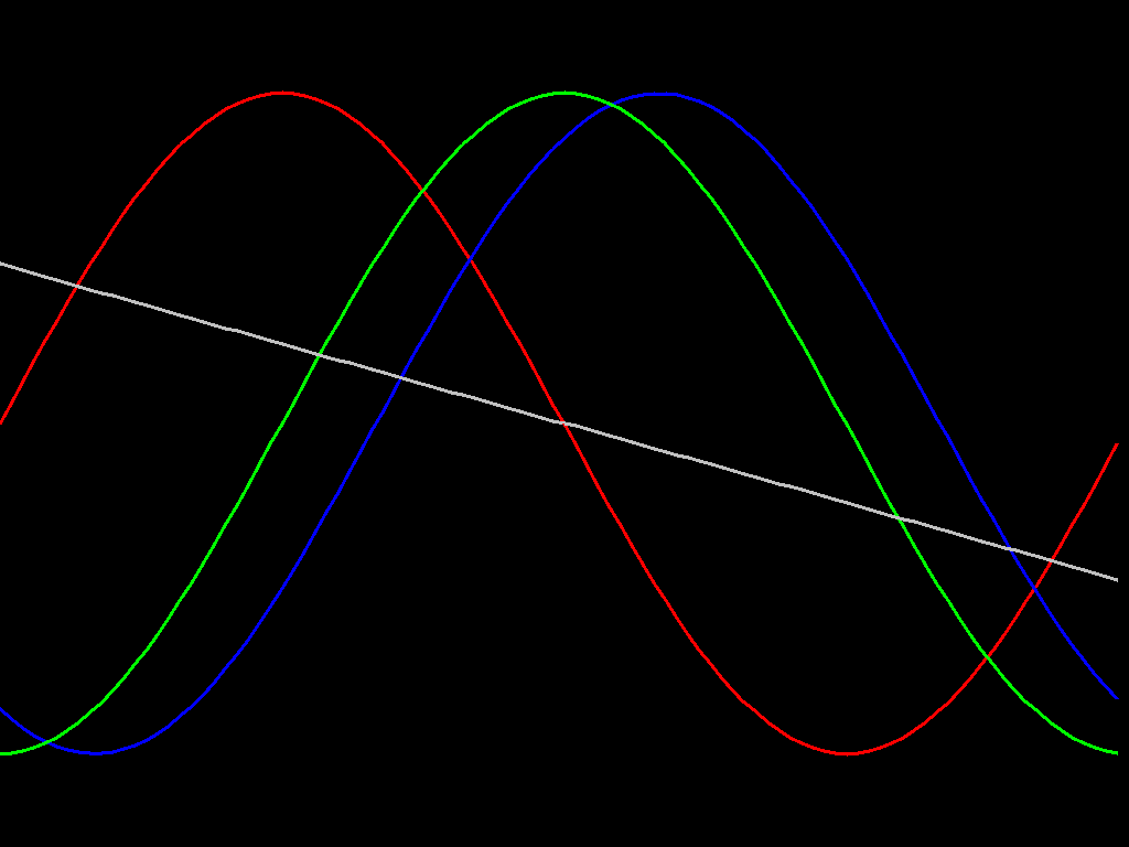
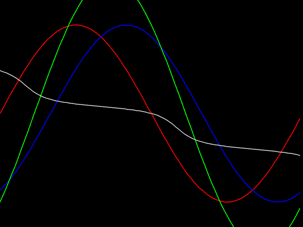
Nonetheless it spurred me to run the simulation, and ±120° or ±240° both work just fine with the unmodified Clarke transform. You only need to negate one of the terms in b = b * 2_SQRT3 + a * 1_SQRT3; if the sensors are spaced ±60°. So now the mystery is, why does yours run better that way?
As far as I can tell from a 3D model with 8 rotor magnets and 2 sensors spaced 120 degrees around the shaft, there shouldn’t be any unexpected effects like you get with 12 magnets where three sensors spaced equally around the rotor all see the same value due to 12 being a multiple of 3. All multiples of 30 mechanical degree spacing (except for multiples of 90°) work out to 120 or 240 electrical degrees. You have to offset by 15 mechanical degrees (60 electrical degrees divided by 4 pole pairs) to get the 60 electrical degree phase difference.
Looking at your image in post 21 again, it’s odd that the phase difference between the a and b waves seems to be a bit larger in the CW case. Maybe it’s just an artifact of the low time resolution. But it looks like around 100-110°, so the 60° spacing calculation should perform much worse than 90 or 120.
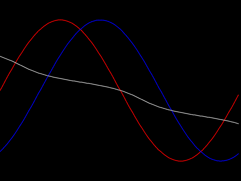
Here’s the simulation code. You won’t be able to run it directly without my ScreenBuffer code and SDL setup, but shouldn’t be difficult to adapt to any other line drawing function.
	float _1_SQRT3 = 0.57735026919f;
	float _2_SQRT3 = 1.15470053838f;
	const int W = 8; // Width of each table row
	const int numPoints = 100;
	int table[numPoints*W];
	for (int i = 0; i < numPoints; i++)
	{
		float phase = i * M_PI*2 / numPoints;
		float a = sin(phase), b = sin(phase - 120*M_PI/180);
		float b90 = a * _1_SQRT3 + b * _2_SQRT3;
		float angle = atan2(a, b90);
		table[i*W+0] = 384 - (int)(a*300);
		table[i*W+1] = 384 - (int)(b*300);
		table[i*W+2] = 384 - (int)(b90*300);
		table[i*W+3] = 384 - (int)(angle*290 / (2*M_PI));
	}

	int prevX = 0;
	int prevA = table[0], prevB = table[1], prevB90 = table[2], prevAngle = table[3];
	for (int i = 1; i < numPoints; i++)
	{
		int x = i * 1024 / numPoints;
		int a = table[i*W+0], b = table[i*W+1], b90 = table[i*W+2], angle = table[i*W+3];
		ScreenBufferDrawLine(screen, prevX, prevA, x, a, 0xff0000, 3, NULL);
		ScreenBufferDrawLine(screen, prevX, prevB, x, b, 0x0000ff, 3, NULL);
		ScreenBufferDrawLine(screen, prevX, prevB90, x, b90, 0x00ff00, 3, NULL);
		ScreenBufferDrawLine(screen, prevX, prevAngle, x, angle, 0xc0c0c0, 3, NULL);
		prevX = x;
		prevA = a, prevB = b, prevB90 = b90, prevAngle = angle;
	}
And here’s the output:
I think you have the right idea, except I’d word it like (lastA-centerA) and (lastB-centerB) together are a single vector representing a point on a circle. If they’re not the same amplitude then it’s more like an oval so atan2’s angle comes out a little wrong. amplitude_ratio scales b to match a’s range so they trace out a proper circle (which doesn’t need to be a unit circle since the division in tan=y/x cancels out the radius).
Just set lastA = a, lastB = b before the return atan2 in LinearHall::readSensors. But as I said before, only do it for the printing test since there’s a possibility of reapplying Clarke transform if there are no new ADC samples available.
Very well then. I was reluctant to add the zero check since then I also have to add error handling if it never does give a reading, but I suppose that’s good to do anyway incase of passing in wrong pins or whatever. Here is the new release candidate: Arduino-FOC-drivers/src/encoders/linearhall at dev · dekutree64/Arduino-FOC-drivers · GitHub
Very elegant to use enum SensorSpacing
You should also edit the example sketch and explain the new feature
"// hall sensor instance
LinearHall sensor = LinearHall(A0, A1, 11, _90);   //   SensorSpacing can also be set to _60 or _120
I’ve wound many BLDC motors in my life, but never saw a 12 magnet motor. But that brought up the idea of a sanity check, when the wrong PP is set.
PP*2 mod 2 is always 0, but PP*2 mod 3 must be > 0
Racerstar BR1811 and BR2211 are 9N12P configuration. I have a bunch of them, but they're not very good for FOC due to very high cogging.
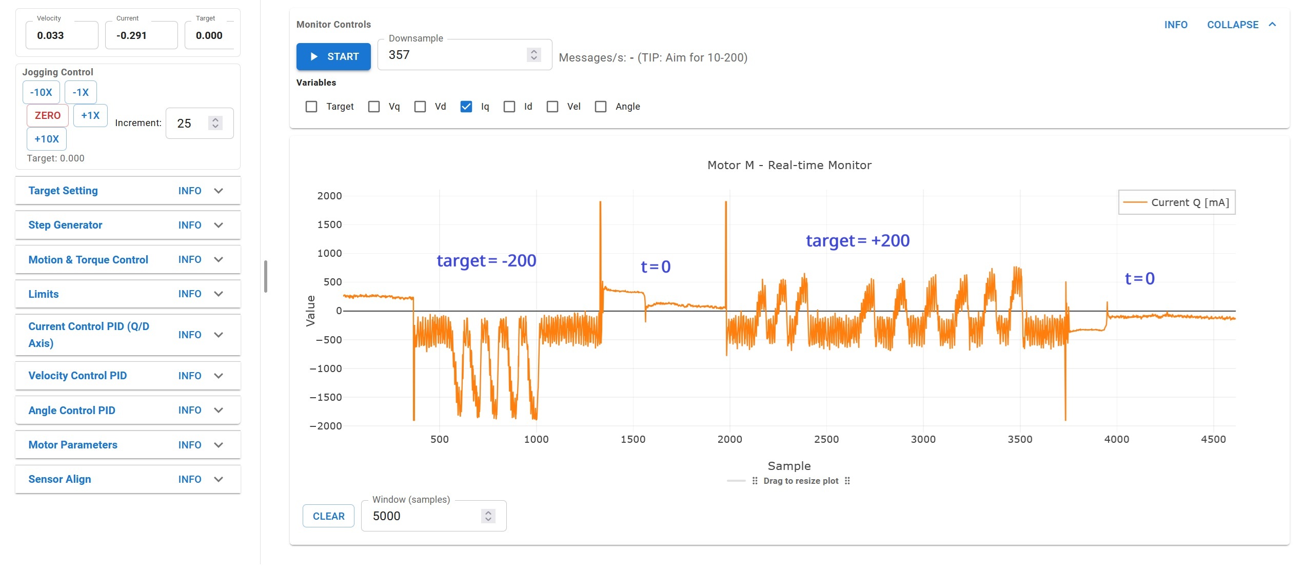
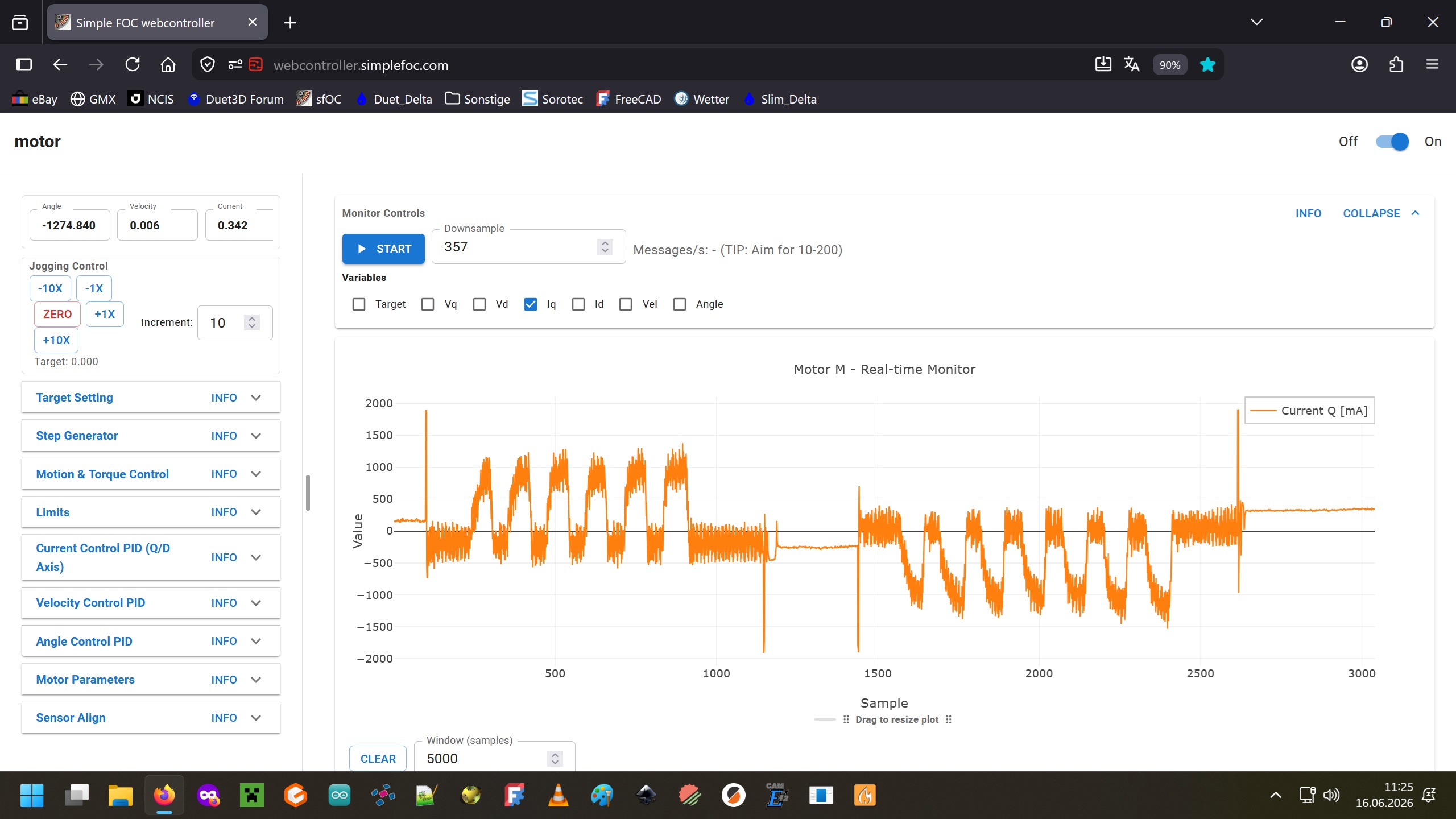
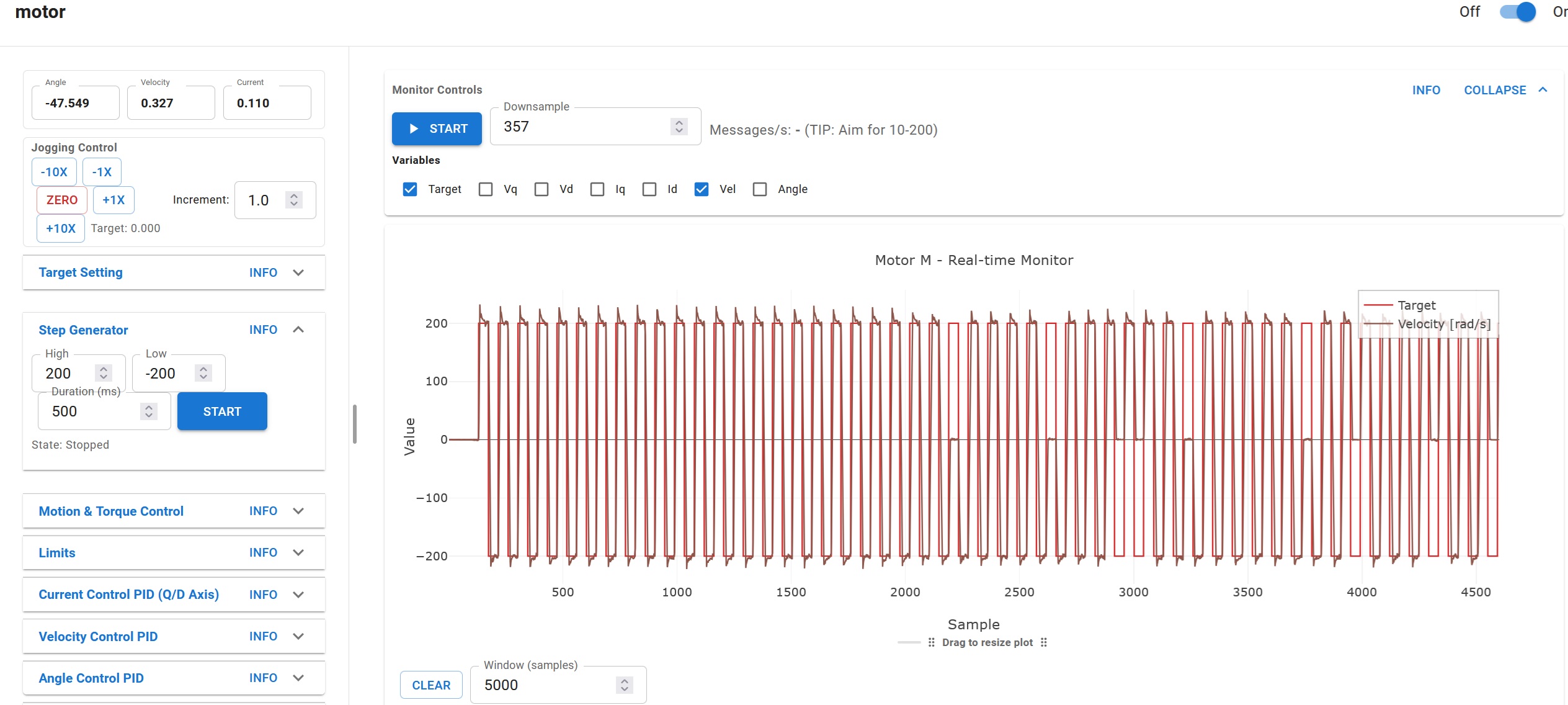
– dekutree64I made some stresstest with the motor, after I reverted to +a 120° formula and it works too.
But I noticed it would run weaker (and hotter?) in CW direction. I modified to 60° again and the issue was reversed. The no load current wasn’t symetric around 0.
I checked my code again and found old centerA/B values in Sensor.init
Corrected the values and the Iq graph looked like that:
Then moved on with longterm testing and noticed hiccups after a while. I haven’t found the cause yet.
All I did was reducing the current_limit but it didn’t help.
What else could it be?
After the first hiccup occures, the motor runs rough, like the timing is off and I have to restart the whole test-rig.
I’ve played around with my standalone sensor.init program which mimics sensor.init(&motor); by spinning the motor manually. It always takes a few full turns back and forth, before the center and amp_ratio value stabilize.
I tried to cancel out glitches by adding a median_3 averaging to min and max values, but the sensor noise still comes through.
So, which values should I trust?
The fresh values, found after a single electric revolution ( like sensor.init(&motor); does)
or the settled_in values, which are glitch free due to median_3, but catch up sensor noise eventually?
I will try floating average noise filtering next.
Can I use the internal velocity LPF for that?
I don’t think there is a right answer to that. Better to go after the root cause sensor noise.
Maybe you’re still getting big spikes after all. Might be worth trying the spike filter from post #12. Then combine with the averaging method from #24 and it should be much better without having to lowpass it. Also could use full 500kHz sampling rate with halls.setBuffers(50, 2); to get even more averaging.
The plot thickens.
I’ve used the median_3 function rather than the threshold variant you posted. ( no threshold_guesswork, just spike elimination), but that wasn’t enough.
The LPFilter after median3 did the trick. I end up with the same ballpark numbers as before, but much quicker.
I also removed the averaging in ReadLinearHalls, because the LPF is much finer and runs “spike free”
I still have to use +/- 1 full turn, but that’s probably an issue with the offcenter magnet disk.
I could only adjust it by eye-balling after I replaced the halls.
What also helped finding the values quicker, was to print results every 50 millies but keep the main loop at full speed.
Thanks for the tip 
Here’s the full sketch, most interesting part might be the comment-section at the end, sort of a diary.
#include <ADCInput.h>
#include <SimpleFOC.h>
#include <SimpleFOCDrivers.h>
#include <encoders/linearhall/LinearHall.h>

ADCInput halls(A0, A1);

LinearHall sensor = LinearHall(A0, A1, 4, true);

//overwrite ReadLH
/*void ReadLinearHalls(int hallA, int hallB, int *a, int *b) {
  int sumA = 0, sumB = 0, count = 0;
  while (halls.available() >= 2)
    sumA += halls.read(), sumB += halls.read(), count++;
  if (count) // There should always be new samples, but if not, lastA and lastB will be reused
    *a = sumA / count, *b = sumB / count;
}*/

//  simple ReadLH
void ReadLinearHalls(int hallA, int hallB, int *a, int *b) {
  while (halls.available() >= 2)
   *a = halls.read(), *b = halls.read();
}

int minA = 2500, minB = 2500;  //  dummy variables for centerA, centerB, amp_ratio
int maxA = 0, maxB = 0;   	   //  inverse preset
int filtA = 1650, filtB = 1650; //  initialize LPF

int hallA[2] = {1650, 1650};	//	 array for median_3
int hallB[2] = {1650, 1650};  //  set to a medium value

int median3(int a, int b, int c)	//	avoiding std::swap
{
    if ((a >= b && a <= c) || (a <= b && a >= c))
        return a;

    if ((b >= a && b <= c) || (b <= a && b >= c))
        return b;

    return c;
}

void setup() {
  Serial.begin(921600);
  _delay(1000);

  halls.setBuffers(8, 2);
  halls.begin(80000);

  sensor.init(1650,1650,1.00f); //  (1926, 1971, 1.1539);

}

void loop() {

  sensor.update();

	filtA = median3(sensor.lastA, hallA[0], hallA[1]);  //  call the spike filter
	filtB = median3(sensor.lastB, hallB[0], hallB[1]);

//	swap values around for next median_3 update
	hallA[1] = hallA[0];
	hallA[0] = sensor.lastA;

	hallB[1] = hallB[0];
	hallB[0] = sensor.lastB;


// adding a LowPassFilter; same value as in motor.LPF_velocity.Tf
	filtA += 0.025f * (sensor.lastA - filtA);
	filtB += 0.025f * (sensor.lastB - filtB);


// use filtA and filtB instead of sensor.lastA/B

  //if (filtA != 1650 ){ //  wait until the motor is spinning = "speedcontrol"
   if (filtA < minA)
      minA = filtA;
    if (filtA > maxA)
      maxA = filtA;
    sensor.centerA = (minA + maxA) / 2;

    if (filtB < minB)
      minB = filtB;
    if (filtB > maxB)
      maxB = filtB;
    sensor.centerB = (minB + maxB) / 2;

   sensor.amplitude_ratio = (float)(maxA - minA) / (float)(maxB - minB);
  //}

// Print stuff every 50 millis but keep full polling speed
 static int32_t lastPrintTime = 0;
  int32_t t = millis();
  if (t - lastPrintTime >= 50) {
    lastPrintTime = t;

	//Serial.print("RangeA:"); Serial.print((maxA-minA)); Serial.print(",");
	//Serial.print("   minA:"); Serial.print(minA); Serial.print(",");
	//Serial.print("   RangeB:"); Serial.print((maxB-minB)); Serial.print(",");
	//Serial.print("   minB:"); Serial.print(minB); Serial.print(",");
	//Serial.print(" lastA:"); Serial.print(sensor.lastA); Serial.print(",");
	//Serial.print("   lastB:"); Serial.print(sensor.lastB); Serial.print(",");
	Serial.print("   centerA:"); Serial.print(sensor.centerA); Serial.print(",");
	Serial.print("   centerB:"); Serial.print(sensor.centerB); Serial.print(",");
	Serial.print("   ratio_1k:"); Serial.print(sensor.amplitude_ratio*1000, 8); Serial.print(",");
	Serial.println("\r");

  }
}

/*	before "speedcontrol"
		maxA:2553,   maxB:2596,   minA:0,   minB:0,   centerA: 1276,   centerB: 1298,   ratio: 0.98,
	after
		maxA:2591,   minA:1256,   maxB:2552,   minB:1392,   centerA: 1923,   centerB: 1972,   ratio: 1.15

	with 60° phase shift
		  centerA: 1925,   centerB: 1959,   ratio: 1.18

	with median_3 averaging
		1926, 1971, 1.1539

	with median_3; LPF 0.05
		centerA: 1884,   centerB: 1859,   ratio: 1.0372

	with median_3; LPF 0.01
		centerA: 1908,   centerB: 1891,   ratio: 1.0260

	with median_3; LPF 0.025	(wrong start values 1250 vs 1650)
		centerA: 1888,   centerB: 1873,   ratio: 1.0237

multiplied ratio by 1000 for better plottability

	with median_3; LPF 0.025; start value 1650; no _delay
		centerA:1926,   centerB:1971,   ratio_1k:1153.58068848,

  with median_3; LPF 0.025; start value 1650; no _delay; simple readLH
    centerA:1927,   centerB:1973,   ratio_1k:1146.25842285,
*/
Are you sure about the correction factor in
– o_lampesensor.init(1924, 1825, 0.822);The green curve (HallB) is already smaller than the orange.When ADCInput is related to audio, is there an oversampling option, like in old CD-players
– o_lampe