tank you very much for your detailed explanation. I really appreciate it if people use their spare time to help other people gaining knowledge to overcome their problems.
We now know, that lowside current sensing is rather not a good way to implement torque control.
But how about current monitoring?
If my adc is way slower than my PWM or if i filter the sensing signal with a lowpass filter it should be possible to detekt overcurrent events such as collision, shouldn´t it? In this case the measured current will allways be a averaged current through the motor.
I’d like to throw in my vote here to keep it more general. The way I see it there are 2 main reasons to do current sensing in BLDC control:
to recover the phase angles via measurement of the current, to be able to drive the FOC algorithm without the need for an encoder, or to improve on encoder only setups in some way
to limit the motor current to some value, usually to prevent something burning up (e.g. MOSFETs, Motor Windings, PCB traces and batteries).
or combination of both reasons…
Reason 1 is a nice feature for SimpleFOC because many setups will be greatly simplified in terms of physical setup and cost if you can get acceptable FOC performance without the encoder.
Reason 2 is a nice feature for SimpleFOC because many new kinds of motor windings can be used, and higher voltage/current setups become possible. With FOC control and the possibility of “holding” a position, current limiting is required to ensure the MOSFETs are operated with a “pulsed” current.
As I understand it, a solution for current sensing for driving FOC requires either 3 shunts, or 2 shunts and some extra calculations, or just one shunt and lots of complex calculations correlated to the algorithm timings.
As I understand it, a solution for current sensing for limiting current is considerably simpler in terms of the software, requires only one shunt, either high or low side, but needs to be implemented “fast”, i.e. in a way that guarantees the current gets limited before the burning starts.
In any case, in my opinion, SimpleFOC should try to do all of these things - current sensing for limiting, current sensing for FOC control, and 3 shunt/2 shunt/1 shunt, and high-side, low-side and inline.
Why? For the same reasons Robin states: SimpleFOC is trying to be a general library, not tied to specific hardware. So its hard to predict which type of current sensing the user will need in their application. In the same way you support multiple angle-sensors, you could support multiple current-sensors
That said, it is obviously best to start with one kind of sensing and build from there.
Perhaps I can be of help, but unfortunately this stuff is a hobby for me, and judging the speed with which my hobby progresses I guess you will be long finished before I can be of any use…
We are aiming to support as many motor+sensor+mcu+driver combinations out there and this will continue for sure.
Current sensing is a new topic for me and for simplefoc and I am eager to dig into it.
At the moment with help of @robin2906 I designed a new SimpleFOCShiled with double shunts in-phase which is going to be a great test-bed for this.
Once when I have a good version of it I will make the files available.
I am uising INA240 current sense amps (vrsion 50V/V) and 10mOhm shunts for starters. But this could be changed to 20mOmh and 20V/V version.
Till then, I have the DRV8302 board that I found some time ago and it has low side current sensors for all 3 phases. I am going to concentrate on it for the first implementation. But as robin already very very well explained the low-side implementation tends to be very hardware specific and might result in dividing the simplefoc library to stm/esp/arduino/teensy separate libraries.
Hi, and thank you for that excellent and detailed explanation. I think I understand most of it but I’d like to take you up on your offer to clarify, if you don’t mind!
The STSPIN830 is a pretty cool driver, but it’s just a driver. It doesn’t have a MCU, so it can’t do FOC by itself, and it uses the current sense input only to limit the motor current (for things like low resistance windings or stall situations I assume). But it can be configured for either 3-PWM or 6-PWM driving, and has some other cool features. It’s very small though, and the PCB layout is (for me) challenging.
I understand fully the argument that sensing the individual phase currents for the purposes of FOC control with just one low side shunt is very difficult, as you describe and illustrate with the table.
But for the purpose of current limiting, when you’re only trying to understand the total current flowing through the system and don’t care about individual phase currents, why would the 1-shunt setup not work?
When T1,T2,T3==0 then the current flowing through the system is also 0, or am I wrong? I guess this state is not a normal state in terms of motor commutation, but can occur due to the PWM?
I would assume that – for the purposes of current limiting --, a single high-side or a single low-side shunt should read the same value?
Isn’t the reason single shunt sensing is ok for current limiting purposes, because the whole system current is flowing through the shunt, regardless of which path it takes through the windings?
Yes absolutely, you can detect collision with low side single shunt. If the motor stall then a huge spike of current will flow through the resistor. In my opinion the best way to do that is to synchronize you ADC with a state of your inverter. With this method you limiting current threshold is set regarding to the maximum current for a phase of your motor.
A low pass filter can also do the tricks but be careful to not set your current limiting threshold too high because state 0 and 7 of the inverter will always lowered your “averaged” current value.
Let a free running ADC sampling at low frequency is not a good option in my opinion because if you have no luck you will always sample state 7 or 0 of the inverter
Sorry I was thinking about the STSPIN32F0 Yep exactly the shunt resistor is used only for current limiting.
With a low side current sensor you can’t know “the total current flowing through the system” you can only know one phase current at time
But you are completely right, in a current limiting application a low side shunt can be enough because you don’t mind to know exactly which phase overconsume. You just have to observer the shunt voltage, if it rise above a threshold you have to cut power down as fast as you can before it’s too late This feature is present in the STSPIN830.
But again with a low side current sensing it’s difficult to know all the current flowing through the 3 coils of the motor you need a complex algorithm for this purpose.
Yep the sum of the 3 current will be 0. It can happen when you do FOC with your motor.
Yes high or low side will sense the same value.
The high side sensor is more difficult to build but you can protect your design against a short to ground.
With a low side resistor it’s easy to build but you cannot detect if a branch of your inverter is shorted to GND because each side of your shunt resistor will be connected to GND.
Again not the whole current flowing through the motor, just the current flowing through one phase at time.
Is it important to know the precise value and progression of current values? Or would it be more useful to know the exact moment current passes a few specific (pot adjustable) thresholds? In that case, a flash ADC with comparators triggering interrupts might be used. No more concerns about sampling duration.
Tourque ripple is “jitter” or anisotropy in the motors torque. I.e. the force the motor can provide is not “smooth”.
I think it typically refers to constant load situations, I.e. while holding or driving with constant speed?
I’d really like to understand it better myself, so if anyone has insights I’d be pleased to hear them.
But I think, if I understand correctly, that basically torque ripple is undesirable as motion will be less smooth, and it can be audible.
Also, the problem exists to different degrees depending on different parameters - things like load, rotation speed, PWM freq., etc…
So you want to avoid setups which work well for some parameters, but develop high torque ripple for others…
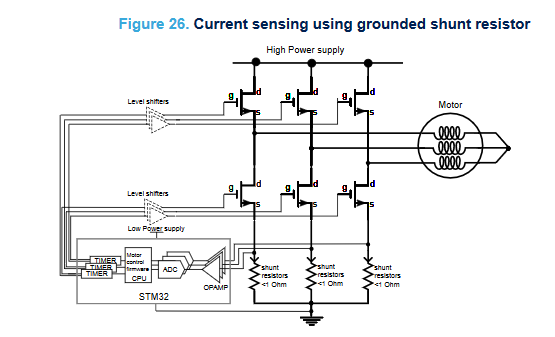
once again i`m struggling with low side current sensing. In AN5306 ST proposed a lowside current sensing with the STM32G4 series. Here is a screenshot.
How can this be done without damaging the the chip? As far as i understand the switching process of the three halfbridges, there is a freewheling current inbetween every positive pulse of the top side pwm cycle. This current flows “backward” through the shunt and through the freewheling diode of the lowside mosfets. So this current causes a negative voltage drop at the shunt resistor.
You ask excellent questions! I have been wondering about these things myself as I wrestle with the design of a current sensing driver.
My take on this: when doing low side sensing, the common mode shifts are small, and the negative voltage seen across the shunt is usually only a small mV value. While the common mode of the op amps should be 0 - VCC, they can tolerate negative voltages in the small mV amounts, and it does not matter.
Some of the external current sense amp chips explicitly mention this in their datasheets.
So its just a guess from a relatively inexperienced person, but that’s my take on why they’re doing this.