Where does that board places the shunt resistors? How is the signal amplified?
The board places 3x shunts resistors (0.003 OHM 1% 3W) on the ground side of the lower mosfets. So I’m guessing similar to your Dagor controller @David_Gonzalez. The kit is rated to 40A assuming you have drone propellers blasting madly down at it!
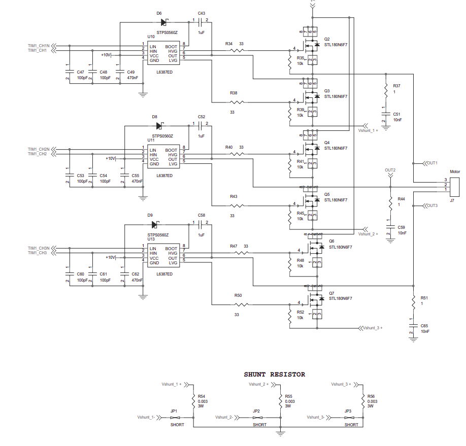
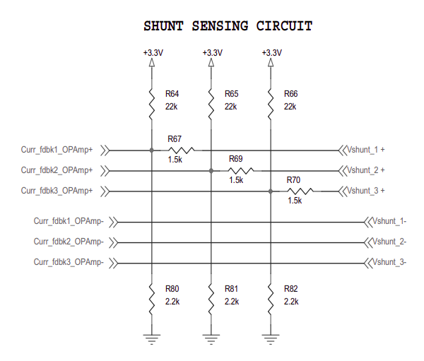
Those vshunt_x+ and vshunt_x- then feed into what looks like a pullup/pulldown circuitry
And the
Curr_fdbkX_OPAmp+ and Curr_fdbkX_OPAmp- feed into special pins in the stm32g431 - these pins can be configured to use internal op-amps.
The stm32g431 has 3 internal opamps each with 4 built-in gain values with 1% accuracy. Configuring pins/opams, I suspect, will be tough on stm32duino as any macros/libs that exist will be for STM32CubeG4
Hi Owen,
if somebody knows better, pls proof me wrong. But i think that low side current sensing can be a problem if you can not ensure, that the current in the shunt resistors allways flows in “positive” direction. There might be a case during free wheeling where the voltage drop becomes negative due to inverted current flow. I dont know whether the i/o pins of the stmg32g4 can handle a negative voltage.
Beste regards
Anderson
Thanks @Owen_Williams! I’d like to see a raw graph from the ADC with your setup and compare it to mine.
Hey Guys, very very interesting topics here!
I’ve started working on the current sensing addition to the SimpleFOCShield and I’m not sure what is the best approach to go with at the moment.
Here is the link to the L6234 datasheet (page 3), they used only one shunt resistor and measured only one current.
As opposed to all that that is usually discussed in terms of BLDC motors (three or two current measurement).
Basically with one current (overall current) you cannot know the motor position but you can still control its torque. Limit it and so on…
I am thinking this is actually not a bad idea, at least for SimpleFOCShield.
What do you guys think?
Hmm, could go either way. What the world really needs is an open-source cross-platform firmware that does true FOC (advancing voltage phase to compensate for current lag at high speed) so we can quit duplicating the hard work again and again. But L6234 has such low current capacity that it’s pretty much only usable for gimbal motors, which can’t go fast enough for FOC to make a big difference anyway. So the only reason to do 2 sensors would be to provide a development platform for yourself, but you could just use a different board for that.
Hello,
Anyhow, It also is totally possible to do a FOC with only one shunt measure with a very good performance.
Hi Antun,
Be careful here, with only one shunt resistor you will be screwed…
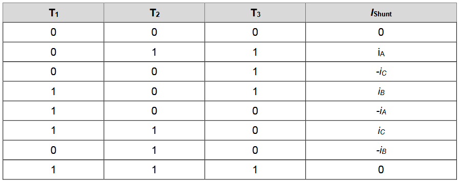
In the tab below you will find the current you will sample with the single shunt topology depending of the state of the inverter when you sample the voltage drop across the shunt resistor.
With this approach you will never know the total current flowing through the 3 coil of the motor because the coil will never be (hopefully) connected to the shunt resistor at the same time. So you will be unable to make a torque controller or a torque limitation…
If you want make a torque controller with this single shunt topology you will have to:
-
Synchronize your ADC with the state of T1 T2 and T3. (Difficult to archive with Arduino and esp32, possible with stm32)
-
Find which commutation sequence have the highest Ton time for the period and make your ADC ready to convert during this time. (You have to do this because if you Ton is too low regarding your ADC acquisition time you are not able to sample the volatge drop with your ADC). → This will not be an easy neither fun task to implement this logic… I will pray for you if you go that way

-
Then acquire 2 current and compute the third current with i1+i2+i3=0 (easy on Arduino, stm32, esp …)
-
Compute your torque controler and power limitation algorithm.
As Marc_O said, it can be done and with good performances, I’m agree with him. BUT the truth is: It have been done and it work well … but on a fixed platform, with a fixed hardware.
Don’t hesitate to ask if it’s not clear !
Best regards,
Hey guys,
What I had in mind was to measure the overall current draw of the L6234. not just one line or phase.
Basically, I would not be able to use this value for foc but it would still be a good value for torque control.
Basically, keep FOC using voltage, but close the outer torque loop using current.
It is not a standard approach, but for gimbal motors it just might be good enough. ![]()
Hi Antun,
You cannot measure the overall current draw of the L6234 with the low side shunt resistor as in the page 3 of the datasheet of the L6234. Never in the commutation the current flowing through the 3 coils of the motor flow through the low side shunt resistor at the same time.
You can use a high-side shunt resistor in line with the power line but it’s not accurate and you will need an amplifier on your board.
Best regards,
@robin2906 thanks, I see what you mean.
I would need to adapt the commutation strategy to measure some good values from this sensor. It is more intended for block commutation and back-emf probably.
Ok so what you would suggest is to use two inline shunts and two current sense amps as the simplest solution.
Take a look how NearZero does it. With a ACS723LLCTR-10AU-T. https://www.allegromicro.com/~/media/Files/Datasheets/ACS723-Datasheet.ashx
http://skysedge.us/robotics/nearzero/electrical/NearZeroSchematic.pdf
Some time ago:
When you do low side sensing … hardware engineer is happy, software engineer try to kill himself…
When you do high side current sensing hardware engineer and software engineer are in the same level of trouble.
When you do inline current sensing hardware engineer try to kill himself and but software engineer is happy.
But today,
Thanks to the huge improvements made in current amplifier it easy to do inline current sensing a low cost. So in my opinion if you want keep simplefoc code not too complicated and not too hardware dependent the best option is inline current sensing on the simplefoc shield.
What you do with simplefoc is beautiful because it work on a lot of different platforms. But why FOC solution provided by ST or Texas or NXP are always difficult to use? The engineer at ST, NXP… have not weird mind ![]() The answer is simple : it’s because FOC with good performances is completely hardware dependent, if you have low side current sensing or high current sensing it’s not the same problem, if you have a powerful MCU or an Arduino it’s not the same problem, because some trick doable by an stm32 are not doable with an Arduino.
The answer is simple : it’s because FOC with good performances is completely hardware dependent, if you have low side current sensing or high current sensing it’s not the same problem, if you have a powerful MCU or an Arduino it’s not the same problem, because some trick doable by an stm32 are not doable with an Arduino.
So for me if you want to keep SimpleFOC library not too complicated for the moment you should do in line current sensing on 2 motor phases. The simpleFOC shield price will raise a bit (5 to 6 euros minimum) but it will be usable with arduino, stm32, esp because you will have to add only 2 ADC input to the library.
Hey @slomobile,
As far as I see they have done exactly what I wanted to do. Before I met @robin2906 ![]()
They measure the current drawn from the battery directly (high-side).
Ok @robin2906, thanks for the info. I agree with what you have said. I am going to design the circuit using two phase inline measurement.
And also I think that it is a nice feature for people who are starting in this world that they have a board that does real foc with gimbal motors. If nothing else then from educational perspective.
Hey @robin2906 ![]()
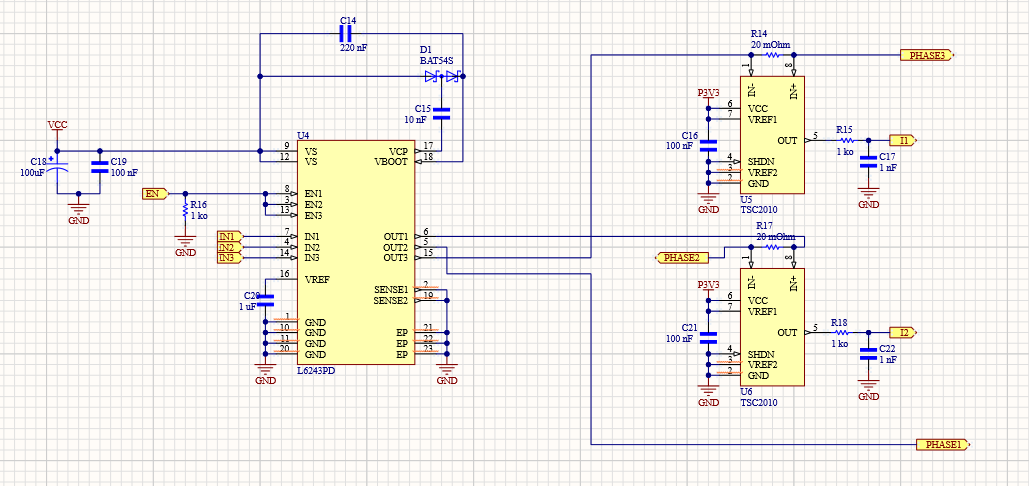
I would like to be able to order everything from JLCPCB (the easiest for me and anyone other who wants to fabricate the board), and unfortunately they do not have TSC2010. I am thinking of using the 50V/V gain INA213AIDCKR + 10mOhm shunt.
At the end I would gain a bit of resolution and loose a bit of range. But I suppose that currents higher than 4Ams will be really rare with this board.
What do you think about this combination?
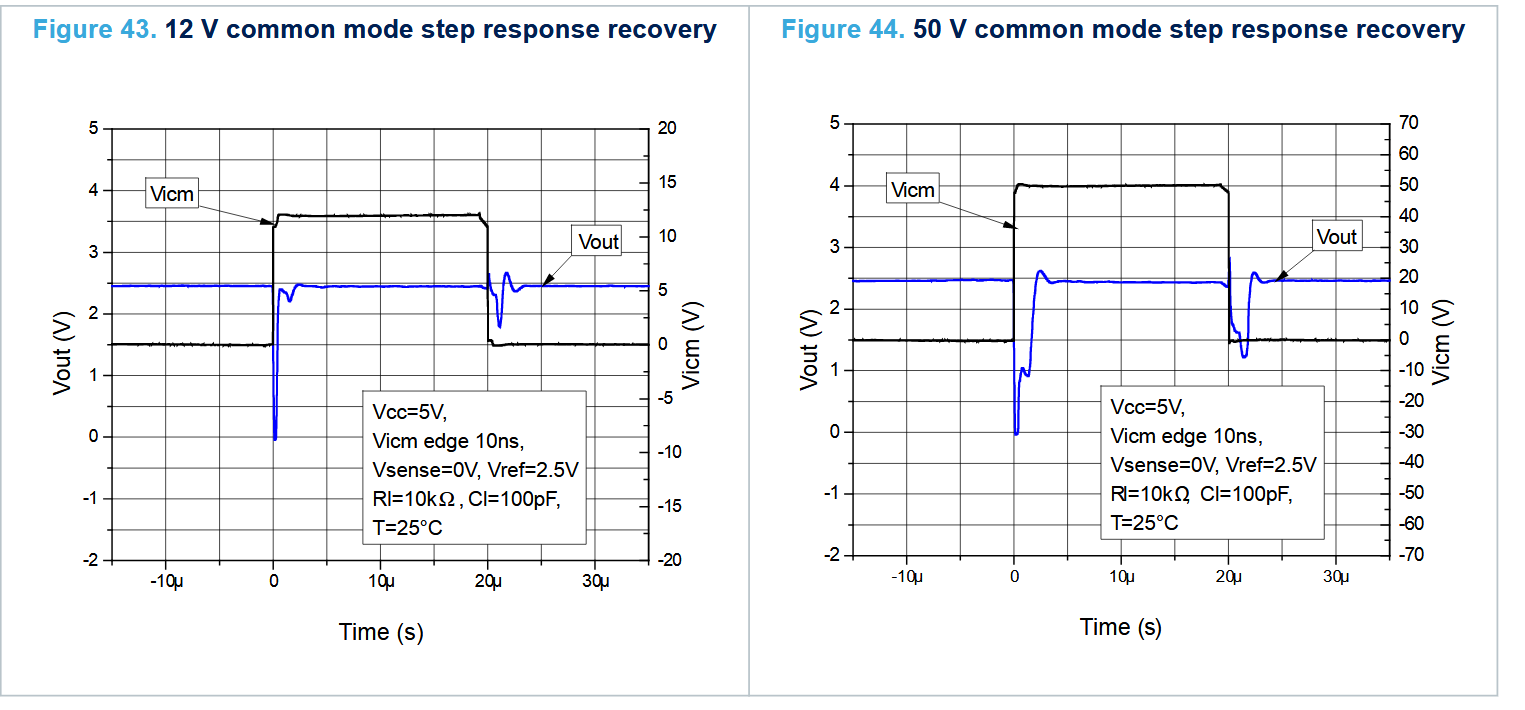
Unfortunately the INA213AIDCKR is a HIGH SIDE current sensor not an in-line current amplifier. It can’t be used as an in-line current sensor because it accept only common mode voltage from 0 to 26V and is rejection is too bad for in-line current sensing:
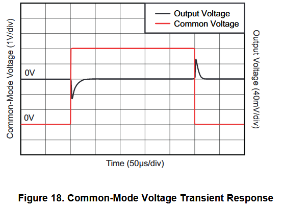
Comparison with TSC2010 from st :
It recover in less than a 1 us for a common mode step of 12V and it is tolerant to up to 70V of common mode step.
Without any affiliation. I have had good experiences with PCBWay - they’ll order TSC2010s for you if your design needs them.
But - the INA*** chips are smaller and cheaper anyway. I’m looking at those as well for the designs I’m doing. There’s some fairly awesome application notes from TI about choosing them, specifically for low side sensing applications. I will try to attach them here…
Hmmm… seems I can’t attach PDFs?
Let me see if I can find the links:
Hi Robin,
I’m wondering why you say this? It seems to me the current must pass through the low side shunt resistor, since Sense1 is Phase 1 & 2, and Sense2 is Phase 3. Where else would the current go? It’s a genuine question on my part - I’m just a humble IT guy trying to learn about this complex world of BLDC control…
I’ve seen other chips (e.g. STSPIN830 but also others) which have this kind of low side sensing setup combined with extra inputs for limiting the current based on those, so at least in some designs it should work? Is it something different about the L6234?
Regards from Vienna,
Richard
Hi Richard,
No problems I will try to explain ![]()
An inverter is basically 6 switches, each can be ON (a current can flow through it) or OFF (no current can flow). I you put a shunt resistor connected between the ground and the low side of the tree branch of the inverter you will get an image of the current flowing through the inverter.
But keep in mind that in each branch of the inverter the lower transistor is always in the opposite state from the upper transistor of the branch. Are you alright with this principle?
Our low side current sensing circuit have a huge drawback: it can get an image of the current only when a low transistor is ON !
When a low side transistor is ON then the current in the coil of the motor pass through the shunt resistor. If we measure the voltage across the shunt we will know the current passing through it.

But what if the low side transistor is OFF? If the low side transistor of the branch is OFF then no current will flow through the resistor because one side of the resistor is connected to the ground and the other side connected to nothing. So if we sample the voltage across the resistor we will know nothing.

If you are confident with this you can deduce the table in my previous message :

For most states of the inverter you will find that the current flowing through the shunt is always the current of one inverter branch at time.
For two state of the inverter (T1 = 0, T2 =0, T3 = 0) or (T1 = 1 T2 = 1 and T3 = 1) you will find that the current flowing through the shunt will be Ia + ib + ic. But if you know Kirchhoff law you already know that in a closed circuit the current entering the circuit is equal to current leaving, so in our BLDC case: i1+i2+i3 = 0 … magic … a lot of current is drawn by the motor but the voltage drop across the resistor is 0… so that why you cannot sample easily the total current with a single low side shunt resistor ![]()
But as you point it, STSPIN830 use a low side shunt, and it work well! Next is an overview of how the ST engineer handle it:
If you know that your inverter is in the state for example T1=0, T2 =1 and T3 =1 then according to the table the current flowing through you shunt resistor is ia. If you are rapid enough you can start your MCU ADC and get the value of Ia.
Then you wait some time until your inverter reach the state T1=1, T2=1 and T3 = 0 and you firing again you’re ADC, you can sample ic.
But be careful … sometime if the state duration is too low, for example 20 us, and your ADC need at least 30 us to sample the voltage drop across the shunt you cannot use this state for sampling ic… That why you need a complicated algorithm to select which inverter state will have a duration compatible with you sampling time depending of the motor operating point …
After when you have the 2 currents properly sampled you can deduce i3 because as always i1 + i2 + i3 = 0 BUT be careful, your pain is not about to end … Here you have to use an algorithm for compensate the lagging in your acquisition because you haven’ sampled ia and ic at the same time (you waited for your inverter to be in the appropriate state for sampling the second current…).
When you have the tree current corrected from the lagging and the rotor position you can compute your torque controller, torque limiter, power limiter or whatever you want “easily”
So to conclude, single low side shunt work, but the price to pay is complex algorithm and a MCU with appropriates peripherals adapted to this kind of operation. STSPIN830 is perfect for this, Arduino is definitely not ![]()
Don’t hesitat to ask if it’s not clear
Best regards