Hi Antun,
Be careful here, with only one shunt resistor you will be screwed…
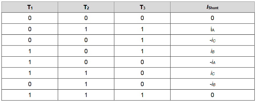
In the tab below you will find the current you will sample with the single shunt topology depending of the state of the inverter when you sample the voltage drop across the shunt resistor.
With this approach you will never know the total current flowing through the 3 coil of the motor because the coil will never be (hopefully) connected to the shunt resistor at the same time. So you will be unable to make a torque controller or a torque limitation…
If you want make a torque controller with this single shunt topology you will have to:
-
Synchronize your ADC with the state of T1 T2 and T3. (Difficult to archive with Arduino and esp32, possible with stm32)
-
Find which commutation sequence have the highest Ton time for the period and make your ADC ready to convert during this time. (You have to do this because if you Ton is too low regarding your ADC acquisition time you are not able to sample the volatge drop with your ADC). → This will not be an easy neither fun task to implement this logic… I will pray for you if you go that way

-
Then acquire 2 current and compute the third current with i1+i2+i3=0 (easy on Arduino, stm32, esp …)
-
Compute your torque controler and power limitation algorithm.
As Marc_O said, it can be done and with good performances, I’m agree with him. BUT the truth is: It have been done and it work well … but on a fixed platform, with a fixed hardware.
Don’t hesitate to ask if it’s not clear !
Best regards,
