A project in mind : force feedback wheel

Yes he is really fast !

BTW, I am currently waiting for Arduino pro micro so I started to look at how to mount the encoder.

I found this clever setup :slight_smile:

A rubber roller is “rolling” on the motor hub. Seems very easy to reproduce, the roller can even be printed using TPU for a good smoothness and adhesion to the wheel.

The question that I have is if simplefoc will cope with multiple rotations of the encoder for a single turn of the motor shaft ?

I mean that if I use a 4096 values magnetic encoder, and as it is an absolute encoder, I will get N zero resets after each turn. Does simplefoc handle this ?

Thanks
JP

No it currently doesn’t handle this. On the one hand I don’t think the adaptation would be such a problem because SimpleFOC cares about electrical angle primarily for the commutation, and there are many electrical revolutions per full turn.
However I think you gave a different problem. For the electrical revolutions the physical Setup of how a motor works guarantees that there is always an integer number of electrical revolutions per full turn. For your setup, what guarantees this? Even if the rubber wheel size is chosen to be an integer multiple of the shaft circumference, it won’t be that precise, and you‘ll have small amounts of slip, meaning you’d lose the motors electrical zero… over Time the errors will add up and the commutation will become increasingly inefficient and eventually stop working.
There was another thread recently discussing a similar idea, and the consensus there was also that it’s not a good idea to separate the FOC sensor from the motor shaft…

I think it would work if you just multiply the reduction ratio with the 4096, so if you have a reduction of 1 to 6.6 you just multiply 4096 times 6.6.

In this setup I would worry about the rubber wheel slipping. I disassembled the motor and in the housing with the magnets I drilled a hole trough the middle off the housing where the bearing is, now you can mount a magnet to the shaft and attach the encoder to the housing.

yes attaching the encoder to the housing is an idea. The drawback is that the I2C wires may tangle if you make several turns with the wheel.
pic

Another idea would be to put the encoder into the hub (on the shaft) and glue the magnet on the rotating hub

see this : https://www.youtube.com/watch?v=T5yhM_fGfm0

JP

yes you are right the roller disalignement is an issue…

Although I had in mind that a calibration could be done when starting the wheel.

Another option could be to add a timing belt. But this wouldn’t correct the other issue (Nx turns per shaft revolution)…

BTW, this video alone is useless… Here is the full article.

I do enjoy the last video with the tractor sound : awesome !

However I do not understand how the magnets ere fixed in front of the encoder ??? Any idea ?

Ok it’s a clever use of a magnetic ring !

magnetic ring
The encoder is fixed on the shaft part and the small magnetic ring is glued on the rotating hub.

Seems so nice !

Well accuracy will probably be an issue with these magnetic rings…

What he is talking about on the odrive Forum isn’t about accuracy, it’s about the index pulses, Wich aren’t really that important if you calibrate the wheel on startup.

I don’t exactly understand how these “magnetic rings” work.
Are they equivalent to a diametrically magnetized magnet ?
If so what are the indexes ?

So the magnet ring changes from north to south 64 times and each change is a index, because the encoder chip doesn’t know where it’s on the ring, it only knows knows the magnet field that’s above it and thus give a for count out I think.

Ok so if it changes North/South 60 times per turn, then the encoder will read 60 times 4096 values… which is what SimpleFoc does not handle (if I am right ?).

I have just started to design a timing belt rig to rotate the magnet for an external encoder.
timingBeltMount

My idea is to glue a timing belt on the cylinder and use it to make the teeth of the gear.
I will have to be acurate when gluing the belt… I will see if it works ! It should as almost no effort is needed on these gears…Only rotate the magnet !

And as the two gears will have exactly the same number of teeth it must work with simpleFoc !

Another link with magnetic ring magnets : https://discourse.odriverobotics.com/t/project-hoverarm/441/9

As far as I can tell an AS5311 sensor with a magnetic ring should work on the incremental output with simplefoc.

I have progressed on the encoder mount.

Seems to be feasible !

I will keep the aluminium plate of the hoverboard and fit the encoder mount on 2 of the 4 screws which fix the motor axis.

And after an hour of printing the result is there !

I have to cut the screw and put the magnet in place on it ; then the encoder will no longer be a problem !

3 Likes

My integration of this magnetic sensor works but is a little “too big”… So starting from @Franz_Schmidt’s idea I have tried something else :slight_smile: reverse the idea to glue the sensor on the bub --> glue it on the shaft :thinking:

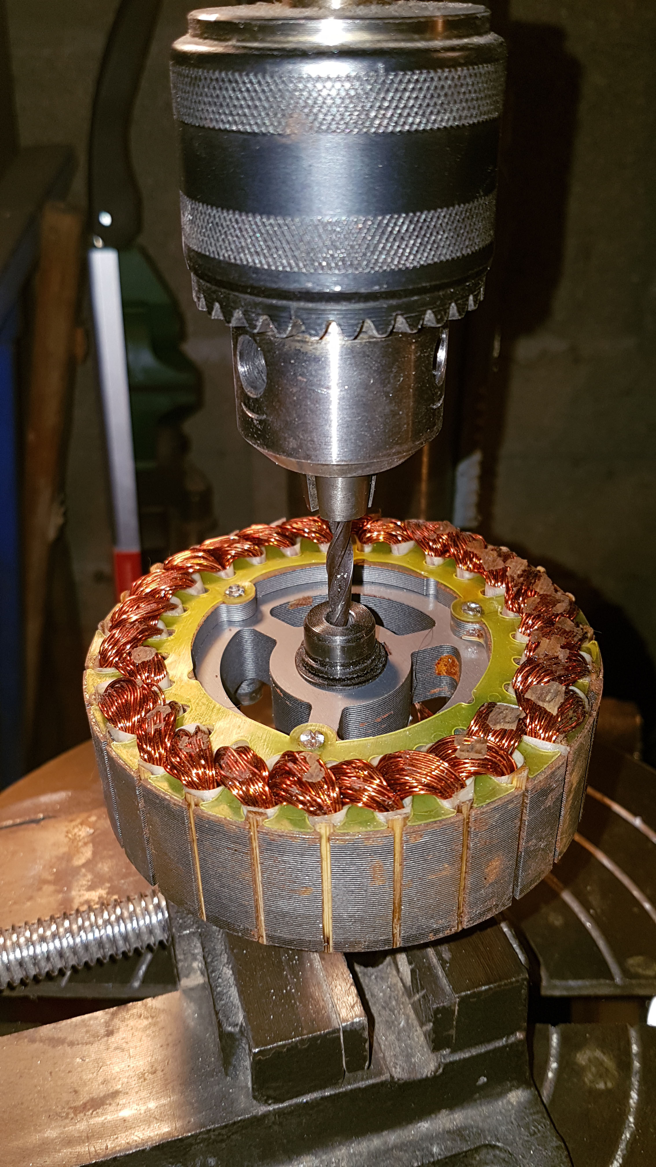
  • drill the motor shaft so that you get a “pipe” into which can go the motors wires as well as the sensor’s ones (6 wires for AMS sensor)
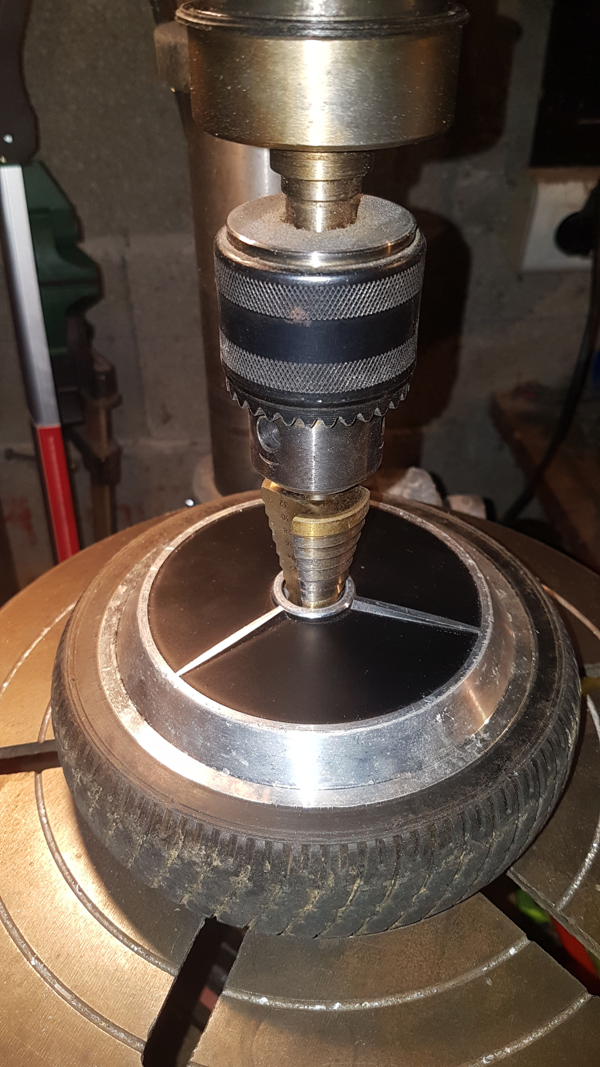
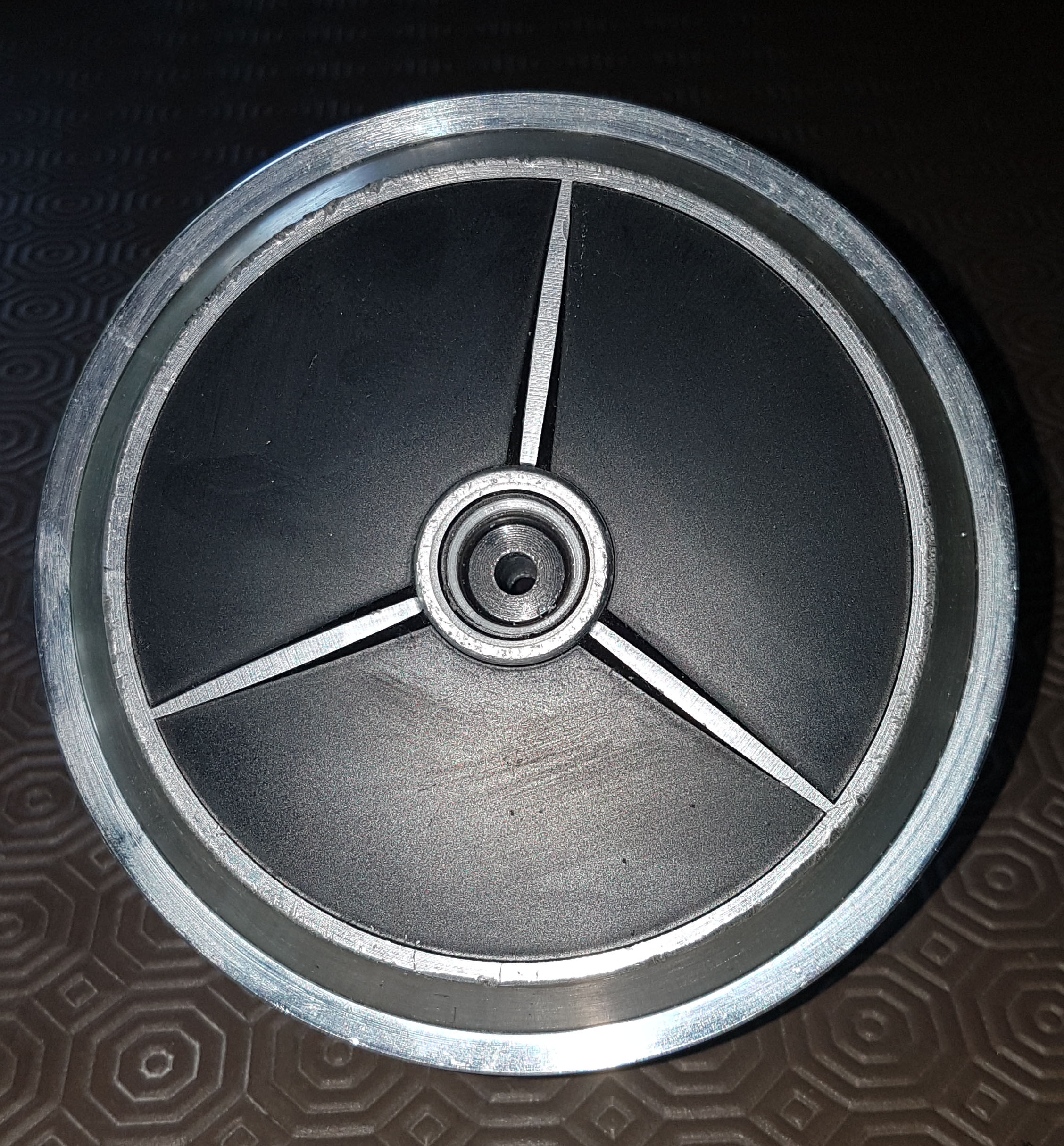
  • drill the outrunner bell so that you can see the shaft

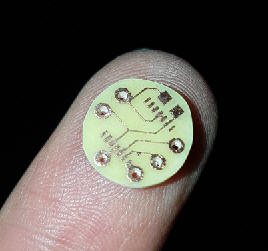
  • design a small pcb on which you will have the difficult task to solder AMS sensor and 6 wires
    pcb
  • glue this on top of the shaft (which is fixed into the bearings)
  • then (easy part) design a small cover to fix the magnet on the rotating bell

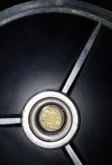
And here is the result (almost) done !
Still have to solder all this (when AS5147U will come)
and then the tests with simpleFoc library :heart_eyes:

JP

3 Likes

That’s actually genius, I’m going to do that on my next hub motors.

1 Like

With the magnet in place it looks like a new motor !

And it should fly @2mm from the sensor, just into the specifications !

3 Likes

Hi, you mention earlier about B-G431B-ESC1

I am interested on how would you connect that to the STM32F4 board for MMOs. I don’t have the slightest clue on how to use these.