Wires between the encoder and the magnet

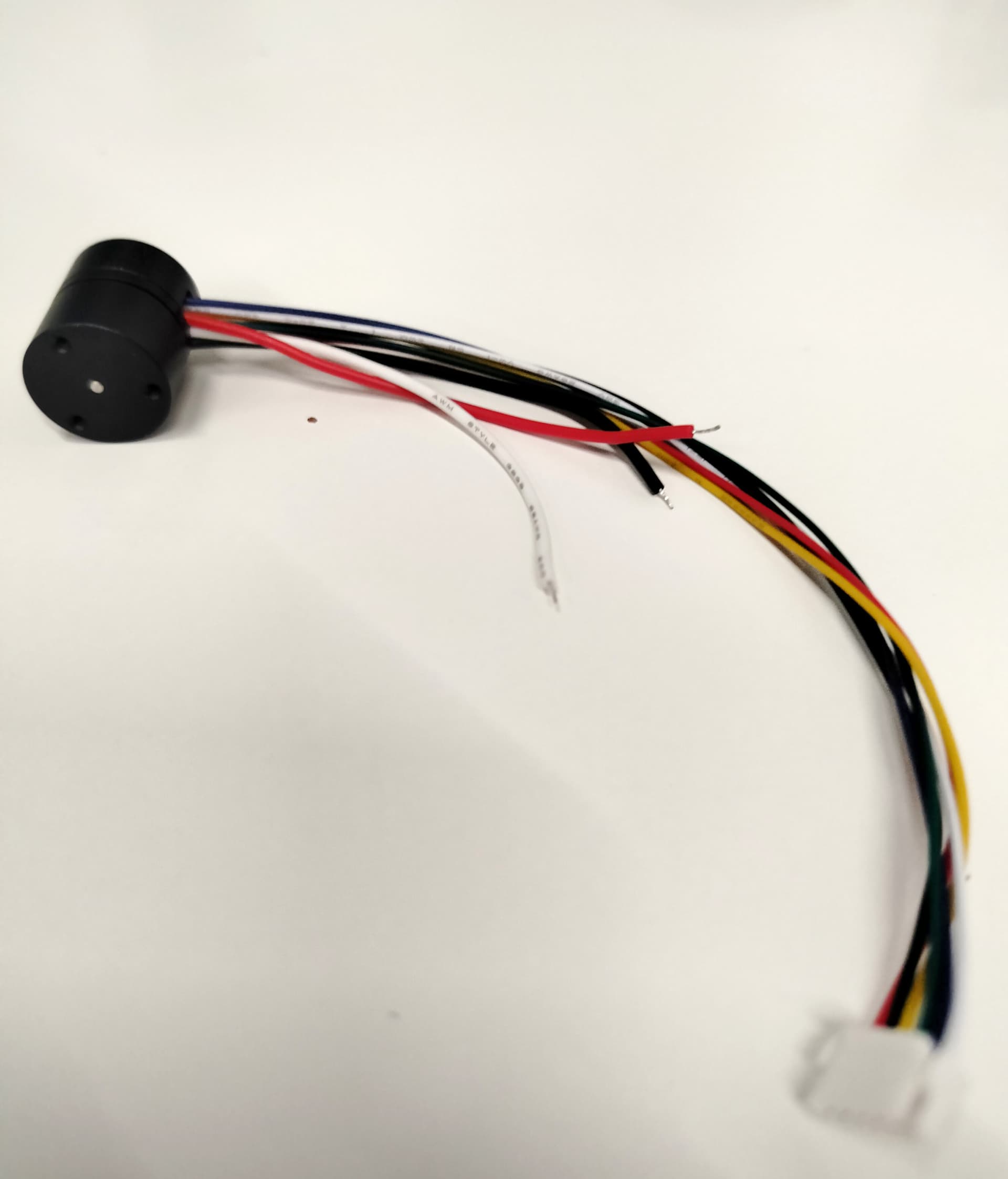
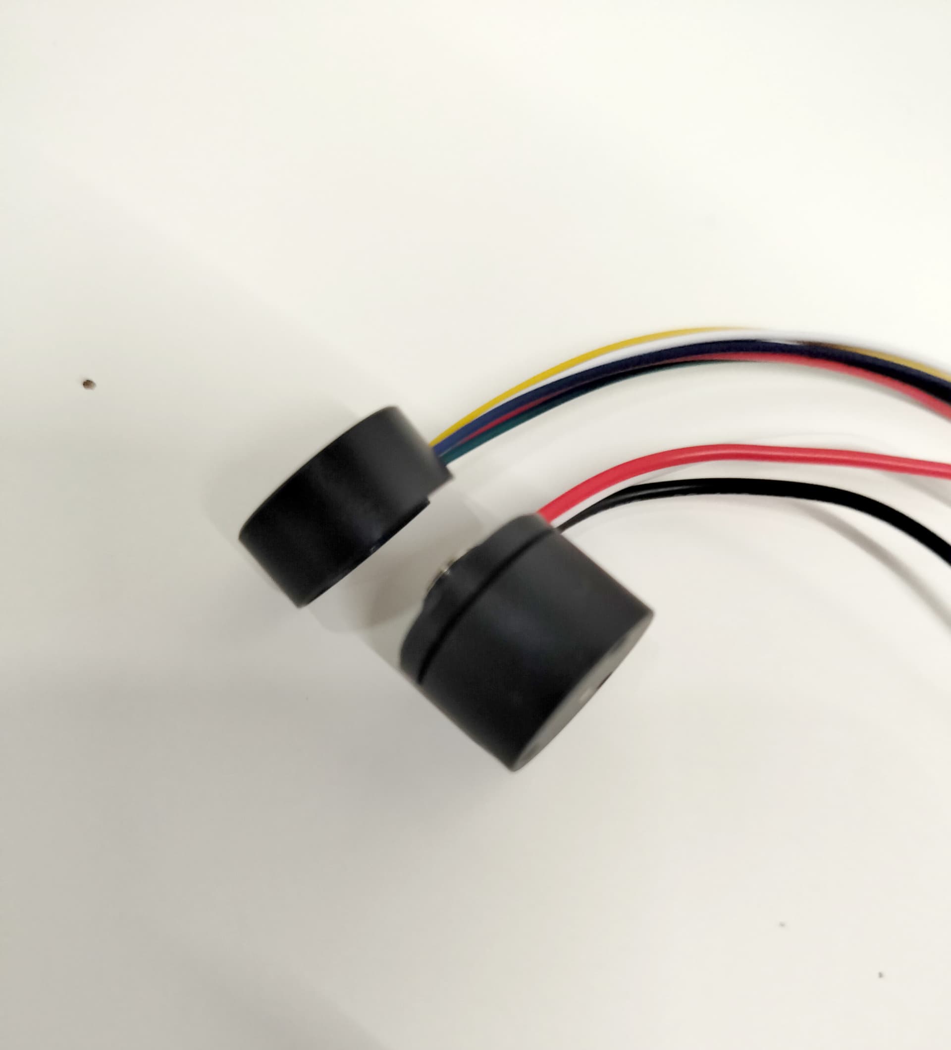
I ordered some miniature motors+AS5048A bundles at a Chinese manufacturer. Usually, their bundles come with the AS5048A wired in PWM. But this time, I specifically requested SPI wiring.

I received this:


Yes, the SPI wires run between the magnet and the AS5048A.

Have you ever seen this?

That seems silly, but it can probably work. Depending on the magnet strength a 1mm air-gap could be ok…

Is the sensor glued in or screwed down? Isn’t it symmetrical so you could just reverse it to solve the problem?

1 Like

It’s glued and asymmetrical :frowning:

I have started sawing the casing, just to see if that can work.

I wasn’t as concerned about the air-gap as I was about potential magnetic interferences caused by the electric signals in the wires…

That’s a real bummer.

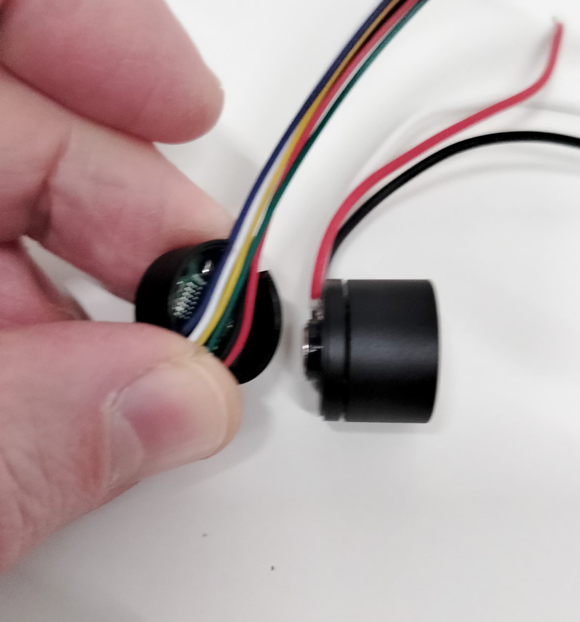
Not sure on that one. It’s a pretty small motor, so maybe it will work. I’d be more concerned about physical interference, as I assume the magnet will touch the cables in this configuration? That has the potential to make the motor’s motion less smooth, if the contact is not with constant friction.

1 Like

Yes, the wires touch the magnet a little bit. Well, we’ll see. I will post here about the results.

Perhaps this is an assembly error, can you unscrew the sensor and rotate through 180 degrees and reattach to housing?

1 Like

Unfortunately this is not an error: the casing is asymmetrical (three screw holes), and so is the sensor PCB. Having the SPI wires going between the magnet and the sensor is the only easy way. What would really be required is a redesign of both the hood and the PCB.

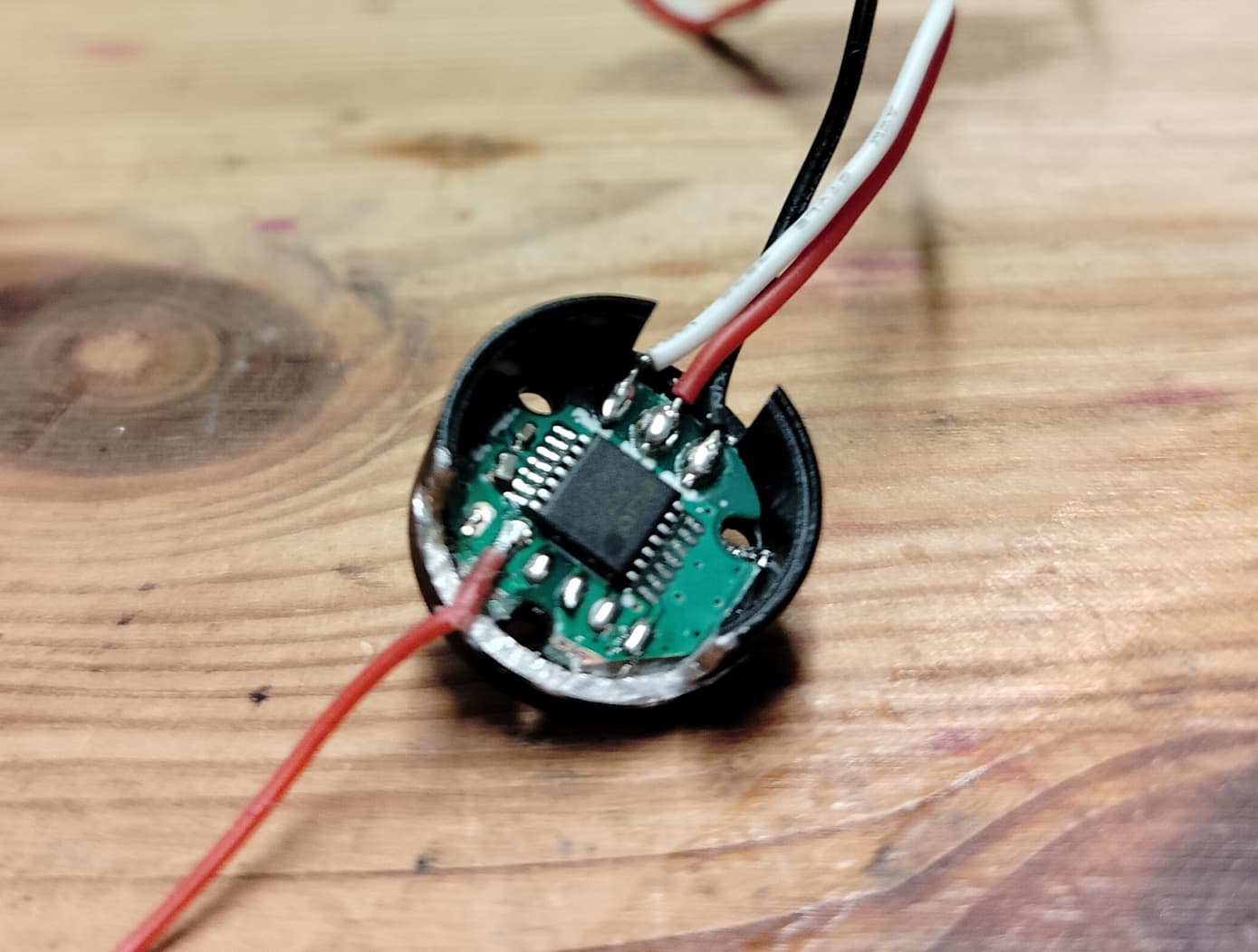
See this picture, where I sawn a new opening (bottom), which only solves half of the problem:

Maybe you can just flip the PCB over and try to sense through the board?
This works for me on MT6701 and MT6835 sensors.

1 Like

Good idea. I will try that if the current setup proves to be problematic and if I’m able to unglue the PCB.

That’s the thing, right, it probably worked - only just - for the original purpose, so they called it good. But it’s not good for general use, not general purpose. That’s what happens when everyone is trying to mix up something on their own. We need standard building blocks. Getting a motor plus angle sensor pair should be easy and cheap.

Here is the results of my tests with the strange encoder wiring:

  • Good news is: the motor somewhat works,
  • but PP check always fails (with random estimated PP between 7 and 9 instead of 6),
  • and PID tuning is very difficult compared to the normal wiring,
  • and the motor gets hotter than with the normal wiring.

Comparison between two exact same motors and encoders, first one with the strange wiring, second one with the normal wiring:

MOT: Monitor enabled!
MOT: Init
MOT: Enable driver.
MOT: Align sensor.
MOT: sensor_direction==CCW
MOT: PP check: fail - estimated pp: 8.25
MOT: Zero elec. angle: 6.28
MOT: No current sense.
MOT: Ready.

MOT: Monitor enabled!
MOT: Init
MOT: Enable driver.
MOT: Align sensor.
MOT: sensor_direction==CCW
MOT: PP check: OK!
MOT: Zero elec. angle: 3.12
MOT: No current sense.
MOT: Ready.