Should it work? are there any modifications that shall be done?
In addition, I would like to add hall sensor circuitry, help will be greatly appreciated.
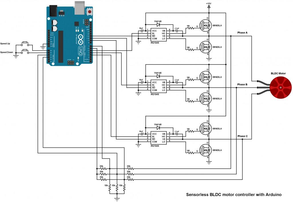
Both IR2101 and IR2104 mosfet drivers should work with simpleFoc, but the circuits you shared are using bemf to calculate the posotion of the rotor which I think is not available in SimpleFoc, but you have hall sensors so you will probably use those.
You should remove the part of the circuit for BEMF sensing, and attach the hall sensors output to the mcu instead.
I don’t think you need any circuitry for hall sensors other that maybe the pullup resitors - it could work with mcu internal pullups, but you have way more flexibility to fix issues with external pullups if you run into issues with noisy signals from hall se sors.
Try it all out on a breadboard first with low voltage/amps.
I have not yet touched current sensing, so I’m as far from an expert as one can get, but for inline current sensing, you should have a current sense resistor which you do not have in this configuration. I think that low side sensing is supported on some mcu as well.
Every solution I’ve seen here is based on some current sense IC (INA, ACS…) and I guess that’s the way to go with current sensing.
BEMF on the other hand is monitored for voltage (not current). Extremely simplified, it works this way: you spin the motor, turn it of, and check the voltage on phases to estimate the magnet position at that precise moment.
The driver portion of the design looks ok. One thing you should watch out for is the state during startup, after power-on, before the MCU pins are set to a defined state. I think you want to pull your shutdown pins low, to ensure the motor doesn’t get accidentally powered during the startup phase.
For the sensing portion, you have BEMF sensing designed here. I think its ok for lower power motors, for higher power I would add some ESD protection to protect the MCU pins against spikes.
But SimpleFOC at the moment does not use the BEMF. As others have pointed out, we support current sensing, in-line or low-side, with 2 or 3 shunt resistors.
For current sensing you need a different circuit, with a shunt resistor and op-amp (or current sense amp).
Consider adding some debouncing to your buttons, a capacitor doesn’t cost much and can make the operation more reliable.
I’m only looking at the picture in a high level way. I didn’t check the details of your circuit:
gate resistor sizing and FET timings
UNO pin assignment, make sure the pins used for IN signals are PWM pins
This picture is from the Diy Esc that casainho introduced in this forum.
I have made a few pcbs, with different drivers(ir2101, u3216, fd6288,eg2134), different mcus(stm32f103,stm32g070,stm32G030), and different mosfet(To220, SO8). For reference I also got a G_431_ESC.
The drivers are based on schematics found on this forums. The difference between them lies in the parts highlighted in the picture.
The one like this works like the G_431_ESC at 25khz,
for others, that only have a gate resistor , I have to decrease the PWM Frequency to 15Khz, one even to 5khz(side effects are more current draw while spinning, or motor not spinning at all and drawing a lot of current even at 1V).
The Questions are:
1: Can I calculate these parts for individual mosfets(Gate resistor, Capacitor OC1)? The gate resistors in example schematics are different, ranging from 2R2 to 1K.
2: Why is there even the capacitor OC1? I have read that the mosfets gate charge capacitance should be low. Does this capacitor increase it?
3: What is the purpose of RS1 and CS1?