I’m asking you about a problem I’m having using the simpleFOC lib. I was using a BE8108 100Kv motor. The same as this one
For the encoder I use an as5600 in i2c.
And for the controller I use a B-G431B-ESC1 board or a VESC flipsky 6.7 board.
My question concerns torque control in FOC_current mode. I have a problem with the control: when I send a 0 setpoint, the motor races and never stops. Similarly, when I reverse the setpoints, the motor doesn’t change direction but races.
Do you have any idea where this might be coming from?
attached code :
#include <Arduino.h>
#include "Wire.h"
// #include <board_vesc_6.h>
#include <SimpleFOC.h>
BLDCMotor motor(21);
// BLDCDriver6PWM driver(H1, L1, H2, L2, H3, L3, EN_GATE);
// InlineCurrentSense current_sense = InlineCurrentSense(0.0005, 200, CURRENT_1, CURRENT_2, CURRENT_3);
BLDCDriver6PWM driver = BLDCDriver6PWM(A_PHASE_UH, A_PHASE_UL, A_PHASE_VH, A_PHASE_VL, A_PHASE_WH, A_PHASE_WL);
LowsideCurrentSense current_sense = LowsideCurrentSense(0.003, -64.0 / 7.0, A_OP1_OUT, A_OP2_OUT, A_OP3_OUT);
MagneticSensorI2C sensor = MagneticSensorI2C(AS5600_I2C);
float target = 0.0;
Commander command = Commander(Serial);
void doMotor(char *cmd) { command.motor(&motor, cmd); }
void setup()
{
Serial.begin(115200);
delay(1000);
// while (!Serial) {};
Serial.println("Setup");
SimpleFOCDebug::enable();
command.add('M', doMotor, "motor");
motor.useMonitoring(Serial);
motor.monitor_downsample = 0; // disable monitor at first - optional
driver.pwm_frequency = 400000;
driver.voltage_power_supply = 10;
// driver.voltage_limit = 12; // Max DC voltage allowed - default voltage_power_supply
Serial.print("Driver init ");
// init driver
if (driver.init())
Serial.println("success!");
else
{
Serial.println("failed!");
return;
}
sensor.init();
Serial.println("AS5600 ready");
motor.linkSensor(&sensor);
// motor.current_limit = 2; // [Amps] - if phase resistance defined
// motor.velocity_limit = 20; // [rad/s] 5 rad/s cca 50rpm
motor.voltage_sensor_align = 1;
motor.velocity_index_search = 10;
motor.voltage_limit = 5; // [V]
motor.velocity_limit = 2000; // [rad/s]
motor.linkDriver(&driver);
current_sense.linkDriver(&driver);
// current_sense.skip_align = true;
motor.linkCurrentSense(¤t_sense);
motor.torque_controller = TorqueControlType::foc_current;
motor.controller = MotionControlType::torque; // ControlType::angle;
motor.useMonitoring(Serial);
// motor.monitor_downsample=100;
// motor.motion_downsample=100;
// current_sense.gain_b *= -1;
// motor.PID_current_q.limit = 2;
// motor.PID_current_d.limit = 2;
// these values are very conservative but they can be a good start
// motor.PID_current_q.P = 0.5;
// motor.PID_current_q.I = 1;
// motor.PID_current_d.P = 0.5;
// motor.PID_current_d.I = 1;
// motor.LPF_current_q.Tf = 0.05; // even 0.1
// motor.LPF_current_d.Tf = 0.05; // even 0.1
// motor.PID_current_d.output_ramp=5000;
// motor.PID_current_q.output_ramp=5000;
// motor.PID_current_q.P=1;
// motor.PID_current_q.I=100;
// motor.PID_current_q.D=0.00001;
motor.monitor_variables = _MON_TARGET | _MON_VEL | _MON_ANGLE | _MON_VOLT_Q | _MON_VOLT_D | _MON_CURR_Q | _MON_VOLT_D;
motor.init();
current_sense.init();
motor.initFOC();
}
int i = 0;
void loop()
{
motor.monitor();
command.run();
motor.move();
motor.loopFOC();
// // IMPORTANT - call as frequently as possible
// // update the sensor values
// sensor.update();
// // // // display the angle and the angular velocity to the terminal
// Serial.print(sensor.getAngle());
// Serial.print("\t");
// Serial.println(sensor.getVelocity());
// // // i++;
}
Always start with more simple control before going to foc current to make sure everything works well.
Is it working well in velocity openloop ? In torque/voltage mode ?
Thanks for the fast response,
Velocity openloop works well. and also in torque/voltage mode.
Yeah the frequency is not correct i change it in the mean time, sorry.
EDIT : I just made a small video to illustrate my problem
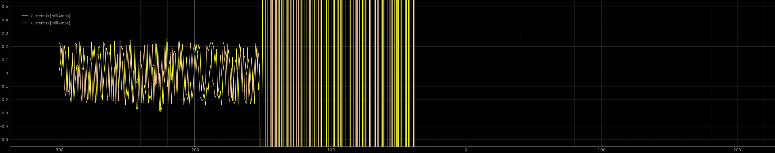
Here a photo of current D and Current Q from commander view.
First part is a setpoint at 0.2 and second part is when i set to 0.
Another things is that the motor is always going in the same direction no matter if i send a positive or negative setpoint.
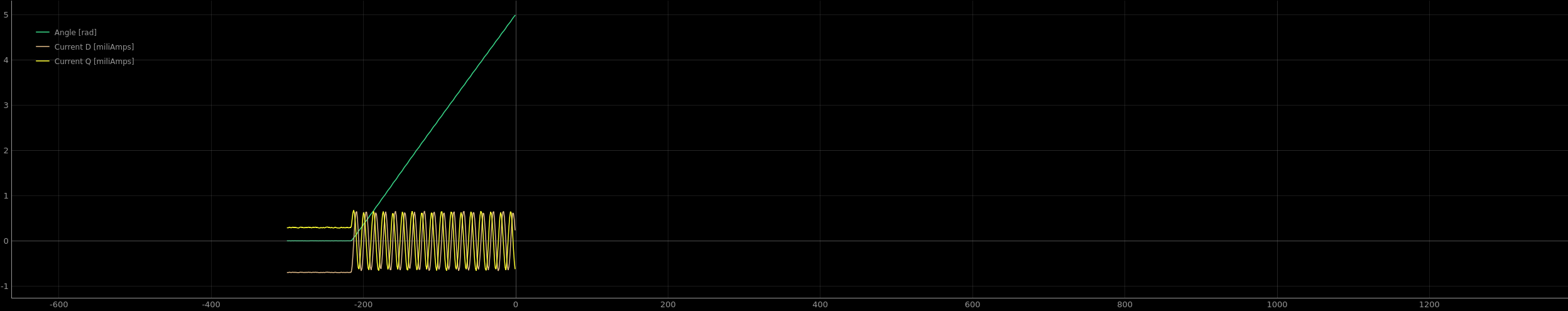
Exactly same setup with DC current/torque mode instead of voltage/torque and a setpoint at 0.
The motor instantly starts to rotate when i enable the motor from commander interface.
The DQ currents shouldn’t be sinusoidal.
How are you getting the DQ currents, are you running this code?
getFOCcurrents(motor.electrical_angle);
What do you mean by enabling the motor in commander ? Isn’t your motor already enabled at startup ?
The way SimpleFOC is implemented now, you shouldn’t disable the driver/motor with low side current sensing or the phase currents cannot be sampled anymore.
You need to check that the phase currents offsets are also correct.
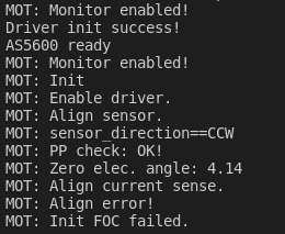
I am surprised the current sense align fails, B_G431B_ESC1 is know hardware so the pins and gains should be correct.
Maybe you can try to increase motor.voltage_sensor_align.
I tried one simple things. I removed the space between the D and H in the flags as in the line you provided and now it’s working like a charm…
I don’t understand why it has an impact.
And I remember that it was working before with the space in the flag and it started it not working a couple weeks ago.
For flags which are “just” defines, like -D HAL_OPAMP_MODULE_ENABLED the space is OK. For lines where there is an assignment, like -D PIN_WIRE_SDA=23 I found that you cannot have any spaces. I think this may be a limit of the compiler?